Table of Contents
Advertisement
Available languages
Available languages
Quick Links
IES3110-8TFM-P
L2+ MANAGED INDUSTRIAL SWITCH
L2+ MANAGED INDUSTRIELLER SWITCH
SWITCH INDUSTRIEL GÉRÉ L2+
L�+マネージド産業用スイッチ
Quick Start Guide
Quick Start Anleitung
Guide de Démarrage Rapide
クイックスタートガイド
CO N SO LE
P1
P2
FA UL T
RIN G
R.O .
9
10
Lin k
1G /2.5 G Lin k/A
Ac t
ct 1G /2.5 G Lin
k/A ct
9
10
SFP
RE SE T
10 /1 00 /1 00 0T
7
8
5
6
3
4
Lin k
1
Ac t
2
Po E-i n-U se
V1.0
Advertisement
Table of Contents

Related Manuals for FS L2+


Summary of Contents for FS L2+
- Page 1 CO N SO LE FA UL T RIN G R.O . Lin k 1G /2.5 G Lin k/A Ac t ct 1G /2.5 G Lin k/A ct RE SE T 10 /1 00 /1 00 0T Lin k Ac t Po E-i n-U se IES3110-8TFM-P L2+ MANAGED INDUSTRIAL SWITCH...
- Page 2 Introduction Thank you for choosing the IES3110-8TFM-P L2+ Managed Industrial Switch. This guide is designed to familiarize you with the layout of the switch and describes how to deploy it in your network. IES3110-8TFM-P Accessories Console Cable x1 Wall Mounting Kit x1 RJ45 Dust Cap x11...
-
Page 3: Hardware Overview
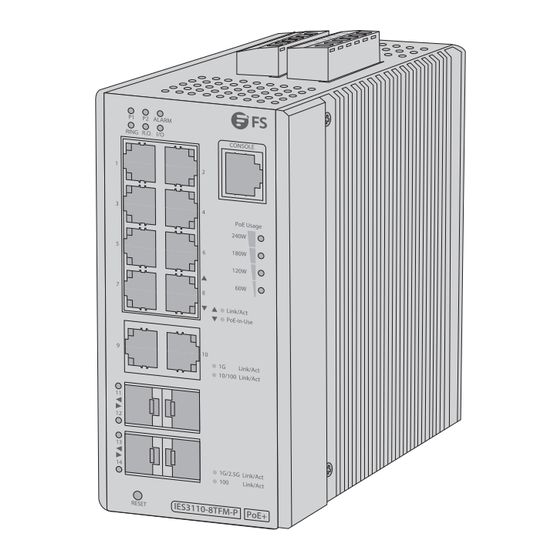
Hardware Overview Front Panel Ports CONSOLE RJ45/PoE+ RJ45 Ports Description 10/100/1000Base-T ports for Ethernet connection. All ports support the PoE+ RJ45/PoE+ function Console An RJ45 console port for serial management RJ45 10/100/1000Base-T ports for Ethernet connection SFP ports for 100M/1G/2.5G connection Front Panel Button RESET Button... -
Page 4: Front Panel Leds
Front Panel LEDs RJ45/PoE+ PoE Usage RJ45 LEDs State Description DC power input 1 is on. Green DC power input 2 is on. Alarm The power input or port has failed. Ring Green The ERPS Ring has been created successfully. System Green The Ring state is in idle mode. -
Page 5: State Description
LEDs State Description The system consumes over 60-watt PoE power budget. The system consumes over 120-watt PoE power budget. PoE Usage Orange The system consumes over 180-watt PoE power budget. The system consumes over 240-watt PoE power budget. Upper Panel Grounding Point DI0 DI1 DO0 DO1 GND GND 1 2 3... -
Page 6: Installation Requirements
Installation Requirements Before the installation, make sure that you have the following conditions ready: Straight-through Cat5/Cat5e cable and DC power wires. Workstations running Windows XP/2003/2008/Vista/7/8/10, MAC OS X or later, Linux, UNIX, or other platforms compatible with TCP/IP protocols. Workstations are installed with Ethernet NIC (Network Interface Card). Serial Port (Terminal) The above workstations come with COM Port (DB9/RS232) or USB-to-RS232 converter. -
Page 7: Wall Mounting
Wall Mounting / 2 . / 2 . E - i 1. Remove the DIN rail mounting kit from the switch. 2. Secure mounting brackets to the back of the switch using the supplied screws. NOTE: Please keep the accessories properly after removal in case of need. 3. -
Page 8: Grounding The Switch
Grounding the Switch DI0 DI1 DO0 DO1 GND GND 1 2 3 Max. Fault Alarm Loading. 24V. 1A 1 2 3 DC Input: PWR1 Alarm PWR2 48-56V , 6A max. DI0 DI1 DO0 DO1 GND GND 1 2 3 1. Connect one end of the grounding cable to the proper earth ground. Max. -
Page 9: Connecting The Sfp Ports
1. Connect an Ethernet cable to the RJ45 port of a wireless AP, IP camera, NVR, or another network device. 2. Connect the other end of the Ethernet cable to the RJ45 port of the switch. NOTE: Make sure the connected devices support MDI/MDI-X. If not, use the crossover Cat5/ Cat5e cable. -
Page 10: Connecting The Console Port
Connecting the Console Port CO NS OL E FAU LT RING R.O. Link 1G/2 .5G Link/ Act 1G/2 .5G Link/ Act RES ET 10/1 00/1 000 T Link PoE- in-Us e 1. Insert the RJ45 connector into the RJ45 console port on the front of the switch. 2. - Page 11 Description Name Live line/Positive Null line/Negative Fault alarm contacts NOTE: 1. The fault alarm contacts are in the middle (3 and 4) of the terminal block connector. Inserting the wires, the product will detect the fault status of the power failure. 2.
-
Page 12: Wiring The Digital Input/Output
Wiring the Digital Input/Output DI0 DI1 DO0 DO1 GND GND 1 2 3 Max. Fault Alarm Loading. 24V. 1A 1 2 3 DC Input: PWR1 Alarm PWR2 48-56V , 6A max. The 6-contact terminal block connector on the switch is used for digital input and digital output. 1. - Page 13 Door Open Detector Power Source DI0 DI1 DO0 DO1 GND GND 1 2 3 Max. Fault Alarm Loading. 24V. 1A 1 2 3 DC Input: PWR1 Alarm PWR2 48-56V , 6A max. Smoke Sensor 3. Wire DI0 and DI1 to Open Detector. NOTE: The two digital input groups are used to monitor two di erent devices.
- Page 14 Con guring the Switch Con guring the Switch via the Console Port Step 1: Connect a computer to the switch's console port using the console cable. Step 2: Start the terminal simulation software such as HyperTerminal on the computer. Step 3: Set the parameters of the HyperTerminal: Baud rate to 115200, Data bits to 8, Parity to None, and Stop bits to 1.
- Page 15 Con guring the Switch via the Web-based Interface Step 1: Connect the computer to an RJ45 port of the switch using a network cable. Step 2: Set the IP address of the computer to 192.168.1.x (“x” is any number from 2 to 254) and the default subnet mask is 255.255.255.0.
-
Page 16: Troubleshooting
Troubleshooting The LED Is Not Lit 1. Check the cable connection. 2. Remove the duplex mode of the switch. Some Stations Cannot Talk to Other Stations Located on the Other Port Check the VLAN settings, trunk settings, or the enabled/disabled port status. The Performance Is Bad 1. -
Page 17: Online Resources
Product Warranty FS ensures our customers that for any damage or faulty items due to our workmanship, we will o er a free return within 30 days from the day you receive your goods. This excludes any custom-made items or tailored solutions. - Page 18 Einführung Vielen Dank, dass Sie sich für den IES3110-8TFM-P L2+ Managed Industriellen Switch entschieden haben. Diese Anleitung soll Sie mit dem Aufbau des Switches vertraut machen und zeigt Ihnen, wie Sie den Switch in Ihrem Netzwerk einsetzen. IES3110-8TFM-P Zubehör Console-Kabel x1 Wandmontagesatz x1 RJ45 Staubschutzkappe x11...
- Page 19 Hardware-Übersicht Ports an der Vorderseite CONSOLE RJ45/PoE+ RJ45 Ports Beschreibung 10/100/1000Base-T-Ports für die Ethernet-Verbindung. Alle Ports unterstützen die RJ45/PoE+ PoE+-Funktion Console Ein RJ45-Console-Port für serielles Management RJ45 10/100/1000Base-T-Ports für die Ethernet-Verbindung SFP-Ports für 100M/1G/2.5G-Verbindungen Taste an der Vorderseite RESET Taste Beschreibung Drücken Sie die Taste für weniger als 5 Sekunden, um den Switch neu zu Reset...
-
Page 20: Leds An Der Vorderseite
LEDs an der Vorderseite RJ45/PoE+ PoE Usage RJ45 LEDs Status Beschreibung DC-Stromeingang 1 ist eingeschaltet. Grün DC-Stromeingang 2 ist eingeschaltet. Alarm Der Stromeingang oder der Port ist ausgefallen Ring Grün Der ERPS-Ring wurde erfolgreich erstellt. System Grün Der Ringstatus ist im Ruhezustand. R.O. - Page 21 LEDs Status Beschreibung Das System verbraucht über 60 Watt PoE-Strom. Das System verbraucht über 120 Watt PoE-Strom. PoE Usage Orange Das System verbraucht über 180 Watt PoE-Strom. Das System verbraucht über 240 Watt PoE-Strom. Obere Seite Erdungspunkt DI0 DI1 DO0 DO1 GND GND 1 2 3 Max.
-
Page 22: Montage Des Switches
Installationsanforderungen Bevor Sie mit der Installation beginnen, vergewissern Sie sich, dass Sie die folgenden Voraussetzungen erfüllen: Straight-Through Cat5-/Cat5e-Kabel und DC-Stromkabel. Workstations mit Windows XP/2003/2008/Vista/7/8/10, MAC OS X oder höher, Linux, UNIX oder anderen Plattformen, die mit TCP/IP-Protokollen kompatibel sind. Auf den Workstations sind bereits Ethernet-NIC (Netzwerkkarten) installiert. Serieller Port (Terminal) Die oben genannten Workstations verfügen über einen COM-Port (DB9/RS232) oder einen USB- RS232-Konverter. - Page 23 Wandmontage / 2 . / 2 . E - i 1. Entfernen Sie den DIN-Schienen-Montagesatz vom Switch. 2. Befestigen Sie die Montagehalterungen mit den mitgelieferten Schrauben an der Rückseite des Switches. HINWEIS: Bitte bewahren Sie das Zubehör nach der Entnahme ordnungsgemäß auf, falls es wieder benötigt wird.
- Page 24 Erdung des Switches DI0 DI1 DO0 DO1 GND GND 1 2 3 Max. Fault Alarm Loading. 24V. 1A 1 2 3 DC Input: PWR1 Alarm PWR2 48-56V , 6A max. DI0 DI1 DO0 DO1 GND GND 1 2 3 1. Schließen Sie ein Ende des Erdungskabels an eine geeignete Erdung an. Max.
- Page 25 1. Schließen Sie ein Ethernet-Kabel an den RJ45-Port eines Wireless AP, einer IP-Kamera, eines NVR oder eines anderen Netzwerkgeräts an. 2. Schließen Sie das andere Ende des Ethernet-Kabels an den RJ45-Port des Switches an. HINWEIS: Stellen Sie sicher, dass die angeschlossenen Geräte MDI/MDI-X unterstützen. Falls nicht, verwenden Sie ein Crossover Cat5/Cat5e-Kabel.
-
Page 26: Anschließen Der Stromversorgung
Anschließen des Console-Ports CO NS OL E FAU LT RING R.O. Link 1G/2 .5G Link/ Act 1G/2 .5G Link/ Act RES ET 10/1 00/1 000 T Link PoE- in-Us e 1. Stecken Sie den RJ45-Stecker in den RJ45-Console-Port an der Vorderseite des Switches. 2. - Page 27 Bescshreibung Name Live-Line/Positiv Null-Line/Negativ Fehlermeldekontakte HINWEIS: 1. Die Fehlermeldekontakte be nden sich in der Mitte (3 und 4) des Klemmenblockanschlusses. Wenn Sie die Drähte einstecken, erkennt das Gerät den Fehlerstatus des Stromausfalls. 2. Die Fehlermeldekontakte sind bei normalem Betrieb GESCHLOSSEN und werden bei einer Störung GEÖFFNET.
- Page 28 Verdrahtung des digitalen Eingangs/Ausgangs DI0 DI1 DO0 DO1 GND GND 1 2 3 Max. Fault Alarm Loading. 24V. 1A 1 2 3 DC Input: PWR1 Alarm PWR2 48-56V , 6A max. Der Klemmenblockanschluss mit 6 Kontakten auf der Vorderseite des Switches wird für den digitalen Eingang und digitalen Ausgang verwendet.
- Page 29 Türö nungsdetektor Stromquelle DI0 DI1 DO0 DO1 GND GND 1 2 3 Max. Fault Alarm Loading. 24V. 1A 1 2 3 DC Input: PWR1 Alarm PWR2 48-56V , 6A max. Rauchmelder 3. Verdrahten Sie DI0 und DI1 mit dem Ö nungsdetektor. HINWEIS: Die beiden digitalen Eingangs-Gruppen werden zur Überwachung von zwei verschiedenen Geräten verwendet.
- Page 30 Kon guration des Switches Kon guration des Switches über den Console-Port Schritt 1: Schließen Sie einen Computer über das Console-Kabel an den Console-Port des Switches an. Schritt 2: Starten Sie die Terminalsimulationssoftware wie z.B. HyperTerminal auf dem Computer. Schritt 3. Stellen sie die Parameter von HyperTerminal ein: Baudrate auf 115200, Datenbits auf 8, Parität auf None, und Stopbits auf 1.
- Page 31 Kon guration des Switches über die webbasierte Schnittstelle Schritt 1: Schließen Sie einen Computer über ein Netzwerkkabel an den RJ45-Port des Switches an. Schritt 2: Stellen Sie die IP-Adresse des Computers auf 192.168.1.x ein ("x" ist eine beliebige Zahl von 2 bis 254) und die Standard-Subnetzmaske ist 255.255.255.0.
-
Page 32: Fehlerbehebung
Fehlerbehebung Das Link-LED leuchtet nicht. 1. Überprüfen Sie die Kabelverbindung 2. Schalten Sie den Duplex-Modus des Switches aus Einige Stationen können nicht mit anderen Stationen kommunizieren, die sich am anderen Port be nden. Überprüfen Sie bitte die VLAN- Einstellungen, Trunk-Einstellungen oder den aktivierten/deaktivierten Port-Status. - Page 33 Kontakt https://www.fs.com/de/contact_us.html Produktgarantie FS garantiert seinen Kunden, dass wir bei Schäden oder fehlerhaften Artikeln, die auf unsere Verarbeitung zurückzuführen sind, eine kostenlose Rückgabe innerhalb von 30 Tagen nach Erhalt der Ware anbieten. Dies gilt nicht für Sonderanfertigungen oder maßgeschneiderte Lösungen.
- Page 34 Introduction Nous vous remercions d'avoir choisi le Switch Industriel Géré L2+ IES3110-8TFM-P. Ce guide est conçu pour vous familiariser avec la con guration du switch et décrit comment procéder à son déploiement. IES3110-8TFM-P Accessoires Câble de Console x1 Kit pour Installation Mural x1 Capuchon Anti-poussière RJ45 x11...
-
Page 35: Aperçu Du Matériel
Aperçu du Matériel Ports du Panneau Frontal CONSOLE RJ45/PoE+ RJ45 Ports Description Ports 10/100/1000Base-T pour la connexion Ethernet. Tous les ports supportent la RJ45/PoE+ fonction PoE+ Console Port de console RJ45 pour la gestion en série RJ45 Ports 10/100/1000Base-T pour la connexion Ethernet Ports SFP pour connexion 100M/1G/2.5G Bouton du Panneau Frontal RESET... - Page 36 Indicateurs LED du Panneau Frontal RJ45/PoE+ PoE Usage RJ45 Statut Description L'entrée d'alimentation en courant continu 1 est activée. Vert L'entrée d'alimentation en courant continu 2 est activée. Alarm Rouge L'entrée ou le port d'alimentation est défaillant. Ring Vert L'anneau ERPS a été créé avec succès. Système Vert L'état de l'anneau est en mode inactif.
-
Page 37: Panneau Supérieur
Statut Description Le système consomme plus de 60 watts d'énergie PoE. Le système consomme plus de 120 watts d'énergie PoE. PoE Usage Orange Le système consomme plus de 180 watts d'énergie PoE. Le système consomme plus de 240 watts d'énergie PoE. Panneau Supérieur Point de Mise à... -
Page 38: Exigences D'installation
Exigences d'Installation Avant l'installation, assurez-vous que vous disposez des éléments suivants : Câble droit Cat5/Cat5e et ls d'alimentation en courant continu. Postes de travail équipés de Windows XP/2003/2008/Vista/7/8/10, MAC OS X ou version ultérieure, Linux, UNIX ou d'autres plateformes compatibles avec les protocoles TCP/IP. Les postes de travail sont équipés d'une carte d'interface réseau (NIC) Ethernet. -
Page 39: Installation Murale
Installation Murale / 2 . / 2 . E - i 1. Retirer le kit de montage sur rail DIN du switch. 2. Fixer les supports de montage à l'arrière du commutateur à l'aide des vis fournies. NOTE : Conservez les accessoires correctement après les avoir retirés, en cas de besoin. 3. - Page 40 Mise à la Terre du Switch DI0 DI1 DO0 DO1 GND GND 1 2 3 Max. Fault Alarm Loading. 24V. 1A 1 2 3 DC Input: PWR1 Alarm PWR2 48-56V , 6A max. DI0 DI1 DO0 DO1 GND GND 1 2 3 1.
- Page 41 1. Connectez un câble Ethernet au port RJ45 d'un point d'accès sans l, d'une caméra IP, d'un NVR ou d'un autre périphérique réseau. 2. Connectez l'autre extrémité du câble Ethernet au port RJ45 du switch. NOTE : Assurez-vous que les appareils connectés prennent en charge MDI/MDI-X. Si ce n'est pas le cas, utilisez un câble croisé...
-
Page 42: Connexion De L'alimentation
Connexion du Port Console CO NS OL E FAU LT RING R.O. Link 1G/2 .5G Link/ Act 1G/2 .5G Link/ Act RES ET 10/1 00/1 000 T Link PoE- in-Us e 1. Insérez le connecteur RJ45 dans le port de console RJ45 situé sur la face frontale du switch. 2. - Page 43 Description Dénomination Ligne Active/Positive Ligne Nulle/Négative Contacts d'alarme NOTE : 1. Les contacts d'alarme sont situés au milieu (3 et 4) du connecteur du bornier. En insérant les ls, le produit détectera l'état de la panne de courant. 2. Les contacts d'alarme sont FERMÉS en fonctionnement normal et S'OUVRENT en cas de panne.
- Page 44 Câblage de l'Entrée/Sortie Numérique DI0 DI1 DO0 DO1 GND GND 1 2 3 Max. Fault Alarm Loading. 24V. 1A 1 2 3 DC Input: PWR1 Alarm PWR2 48-56V , 6A max. Le connecteur du bornier à 6 contacts situé sur le switch est utilisé pour l'entrée et la sortie numériques. 1.
- Page 45 Détecteur de Serrure Ouverte Source d'Alimentation DI0 DI1 DO0 DO1 GND GND 1 2 3 Max. Fault Alarm Loading. 24V. 1A 1 2 3 DC Input: PWR1 Alarm PWR2 48-56V , 6A max. Capteur de Fumée 3. Câbler DI0 et DI1 au Détecteur d'Ouverture. NOTE : Les deux groupes d'entrées numériques sont utilisés pour surveiller deux dispositifs di érents.
- Page 46 Con guration du Switch Con guration du Switch via le Port Console Étape 1 : Connectez un ordinateur au port de console du commutateur à l'aide du câble de console. Étape 2 : Lancez le logiciel de simulation HyperTerminal sur l'ordinateur. Étape 3 : Dé...
- Page 47 Con guration du switch via l'Interface Web Étape 1 : Connectez l'ordinateur à un port RJ45 du commutateur à l'aide d'un câble réseau. Étape 2 : Réglez l'adresse IP de l'ordinateur sur 192.168.1.x ("x" est un nombre quelconque compris entre 2 et 254) et le masque de sous-réseau par défaut sur 255.255.255.0. I nter net Protocol Version 4 ( TCP / IP v4) Prop er t ies General Yo u c a n g e t I P s e t t i n g s a s s i g n e d a u t o m a t i c a l l y i f y o u r n e t w o r k...
-
Page 48: Dépannage
Dépannage L'indicateur LED n'est pas Allumé 1. Véri er la connexion du câble. 2. Annuler le mode duplex du switch. Certains Appareils qui se Trouvent sur l'Autre Port ne Peuvent pas Communiquer entre eux Véri ez les paramètres VLAN, les paramètres trunk ou l'état du port activé/désactivé. Les Performances sont Mauvaises 1. -
Page 49: Garantie Du Produit
Garantie du Produit FS garantit à ses clients que tout article endommagé ou défectueux dû à sa fabrication pourra être retourné gratuitement dans un délai de 30 jours à compter de la date de réception de la marchandise. Cette garantie ne s'applique pas aux articles fabriqués sur mesure ou aux solutions personnalisées. - Page 50 イントロダクション IES����-�TFM-P L�+マネージド産業用スイッチをお選びいただきありがとうございます。この ガイドは、スイッチのレイアウトに慣れることを目的としており、ネットワークにスイッチを 導入する方法について説明します。 IES����-�TFM-P アクセサリー 壁取り付けキット x� コンソールケーブル x� RJ��ダストキャップ x��...
- Page 51 ハードウェア概要 フロントパネルポート ポート 説明 イーサネット接続用の��/���/����Base-Tポート。すべてのポートがPoE+ RJ��/PoE+ 機能をサポート Console シリアル管理用RJ��コンソールポート RJ�� イーサネット接続用��/���/����Base-Tポート ���M/�G/�.�G接続用SFPポート フロントパネルボタン ボタン 説明 ボタンを�秒未満押すとスイッチが再起動します。��秒以上押すと工 Reset 場出荷時の設定に戻ります。...
- Page 52 フロントパネルLED 状態 説明 P� DC電源入力�がオンになっています。 緑色 P� DC電源入力�がオンになっています。 Alarm 赤色 電源入力またはポートに障害が発生しました。 Ring 緑色 ERPSリングは正常に作成されました。 System 緑色 リング状態はアイドルモードです。 R.O. 緑色点滅 リング状態はプロテクトモードです。 電源入力またはポートに障害が発生したか、DIエ DI/DO 赤色点滅 ラーが発生しました。 緑色 そのポートを介したリンクは正常に確立されます。 ��/���/���� LNK/ACT 緑色点滅 スイッチはそのポート経由でデータを送受信しています。 RJ��/PoE+ オレンジ色 ポートはDCインライン電源を供給しています。 PoE-in-Use 接続されたデバイスはPoE受電デバイス(PD)では オフ ありません。 緑色 ポートは����Mbpsで正常に確立されています。 ���� LNK/ACT 緑色点滅...
- Page 53 状態 説明 �� システムは��ワット以上のPoEパワーバジェットを消費します。 ��� システムは���ワット以上のPoEパワーバジェットを消費します。 オレン PoE Usage ジ色 ��� システムは���ワット以上のPoEパワーバジェットを消費します。 ��� システムは���ワット以上のPoEパワーバジェットを消費します。 上部パネル 接地点 端子台コネクタ 注: 黄色の取り外し可能な�接点端子台コネクタは、 DIまたはDOインターフェースに使 用します。 バックパネル DINレール取付用キット...
- Page 54 設置要件 設置する前に、次の条件が整っていることを確認してください: ストレートスルーCat�/Cat�eケーブルおよびDC電源線。 Windows XP/����/����/Vista/�/�/��、MAC OS X以降、Linux、UNIX、またはTCP/IPプロ トコルと互換性のあるその他のプラットフォームが動作するワークステーション。 ワークステーションにはイーサネットNIC(ネットワーク・インターフェイス・カード) がインストールされている。 シリアルポート(ターミナル)。 上記のワークステーションには、COMポート(DB�/RS���)またはUSB-RS���コンバー ターが付属しています。 イーサネットポート ネットワークケーブル: RJ��コネクタ付き標準ネットワーク(UTP)ケーブル。 注: スイッチへのアクセスにはInternet Explorer �.�以上の使用することをお勧めします。 webインタフェースにアクセスできない場合は、 アンチウィ ルスソフ トウェアまたはファイ アウォールをオフにして再度お試し ください。 スイッチの取り付け DINレールへの取り付け ユニットの取り付け ユニットの解除 �. スイッチを上に傾けて、DIN レール取り付けクリップの上端をレールに固定します。 �. スイッチを押し下げて、取り付けクリップの下端をレールにクランプします。スイッチを軽 く振って、しっかりと取り付けられているか確認してください。...
- Page 55 壁取り付け �. DINレール取り付けキットをスイッチから取り外します。 �. 付属のネジを使用して、取り付けブラケットをスイッチの背面に固定します。 注: 取り外した後の付属品は、 必要に応じて適切に保管して ください。 �. 壁に適切なサイズの穴を�つ開けます。壁のプラグを穴に打ち込みます。 �. 拡張ボルトの穴を合わせてボルトを挿入します。 �. スイッチの位置を調整し、しっかりと締めます。 注: 壁関連のアクセサリーは別途購入して ください。...
- Page 56 スイッチの接地 �.アース線の一端を適切なアースに接続します。 �. ネジとワッシャーを使用して、 アースラグを上部パネルのアースポイン トに固定します。 ご注意: デバイスは接地する必要があります。EMD(雷)による損傷は保証の対象外 となります。 注: アース線は付属品に含まれておりません。 RJ��ポートの接続...
- Page 57 �. イーサネッ トケーブルをワイヤレスAP、 IPカメラ、 NVR、 またはその他のネッ トワークデバイスの RJ��ポートに接続します。 �. イーサネッ トケーブルのもう一方の端をスイッチのRJ��ポートに接続します。 注: 接続されたデバイスがMDI/MDI-Xをサポートしていることを確認して ください。 対応し ていない場合は、 Cat�/Cat�eクロスケーブルを使用して ください。 SFPポートの接続 �.互換性のあるSFP光モジュールをスイッチのSFPポートに差し込みます。 �. ネッ トワークケーブルのLCデュプレックスコネクタをSFP光モジュールに接続します。 �. ケーブルのもう一方の端を、 SFP機能付きスイッチ、 ワークステーションのファイバNIC、 またはメデ ィアコンバーターに接続する。 ご注意: 光モジュールを直接無理に引き抜くと、光モジュールやSFPポートが破損す る恐れがあります。...
- Page 58 コンソールポートの接続 �. RJ��コネクタをスイッチ前面のRJ��コンソールポートに挿入します。 �. コンソールケーブルのDB�メスコネクタをコンピュータのシリアルポートに接続します。 電源の接続 DC電源入力には�極端子台コネクタを使用しています。 以下の手順に従って ください: �. プラス/マイナスのDC電源線を電源�の場合は接点�と�、 電源�の場合は接点�と�に挿入します。...
- Page 59 説明 名称 ライブライン/正極 ヌルライン/負極 故障警報接点 注: �. 障害警報接点は、 端子台コネクタの中央 (�と�) にあります。 ワイヤーを挿入すると、 製品は停電の障害状態を検出します。 �. 故障警報接点は、 通常運転時には閉じて通電され、 故障が発生すると開きます。 �. ワイヤーが緩まないように、 ワイヤークランプのネジを締めます。 負極 (-) ピン 正極 (+) ピン ピン �/� ピン �/� 注: 端子台コネクタのワイヤゲージは�� ~ ��AWG の範囲である必要があります。 ご注意: �. ワイヤーを挿入したり、ワイヤークランプのネジを締めたりする場合は、 電源がオフになっていることを確認してください。 �. 電源�と電源�は、二重電源で動作する際の電力負荷バランスのために同じDC電圧 を提供する必要があります。...
- Page 60 デジタル入出力の配線 スイッチの�接点端子台コネクタは、 デジタル入力およびデジタル出力に使用されます。 �. このスイッチには�つのDIグループとDOグループがあります。 �と�はDIグループ、 �と�はDOグルー プ、 �と�はGND (グラウンド) に使用されます。 �. ワイヤーが緩まないように、 ワイヤークランプのネジを締めます。...
- Page 61 ドアオープン検出器 DI� パワー ソース 煙センサー DI� �. DI�とDI�をオープン検出器に配線します。 注: �つのデジタル入力グループは、 �つの異なるデバイスをモニターするために使用され ます。 DO� パワー ソース スプリンクラーシステム DO� �. DO�とDO�をオープン検出器に配線します。 注: �つのデジタル出力グループは、 スイッチ ・ ポートの故障や停電を感知し、 外部デバイ スにHighまたはLow信号を発行するために使用されます。...
- Page 62 スイッチの設定 コンソールポートを介したスイッチの設定 ステップ�: コンソールケーブルを使用して、 コンピュータをスイッチのコンソールポートに接続します。 ステップ�: パソコン上でハイパーターミナルなどの端末シミュレーションソフ トを起動します。 ステップ�: ハイパーターミナルのパラメーターを設定する : ボーレートを������、 データビッ トを�、 パリティをなし、 ス トップビッ トを�に設定します。 ステップ�: 「Connect」 をクリ ックして入力します。...
- Page 63 Webベースのインターフェースを介したスイッチの設定 ステップ�: ネッ トワークケーブルを使用して、 コンピュータをスイッチのRJ��ポートに接続します。 ステップ�: コンピュータのIPアドレスを���.���.�.x ( 「x」 は�から���までの任意の数字) に設定し、 デフ ォルトのサブネッ トマスクを���.���.���.�とします。 ステップ�: ウェブブラウザを開き、 「 http://���.���.�.�」 と入力し、 デフ ォルトのユーザー名とパスワー ド 「admin/admin」 を入力します。 ステップ�: 「Login」 をクリ ックすると、 ウェブベースの設定ページが表示されます。...
- Page 64 トラブルシューティング LEDが点灯しない �. ケーブルの接続を確認してください。 �. スイッチの二重モードを削除してください。 他のポートにある他のステーションと通信できないステーションがある VLAN設定、トランク設定、または有効/無効ポートのステータスを確認してください。 性能は悪い �. スイッチの全二重ステータスを確認してください。 �. ポートの入出力レートを確認してください。 スイッチがネットワークに接続できない �.スイッチのLNK/ACT LEDを確認してください。 �.別のポートを試してください。 �. ケーブルが正しく接続されているか、または正しいタイプであるかを確認してください。 �. 電源を切ります。しばらくしてから、再度電源を入れてください。 ����Base-TポートのLEDが点灯しているが、トラフィックが不規則である 接続されているデバイスが全二重専用に設定されていないかを確認してください。 スイッチの電源が入らない DC電源ケーブルが挿入されていないか、故障している: �. ケーブルが正しく挿入されていない場合は、DC電源ケーブルを交換してください。 �. スイッチの代わりに別のデバイスを接続して、電源が機能しているかどうかを確認してくだ さい。 �. そのデバイスが動作しない場合は、DC電源を確認してください。...
- Page 65 オンラインリソース ダウンロード https://www.fs.com/jp/products_support.html ヘルプセンター https://www.fs.com/jp/service/fs_support.html お問い合わせ https://www.fs.com/jp/contact_us.html 製品保証 FSは、 お客様が弊社の仕上がりに起因する損傷または不良品について、 製品を受け取った日から�� 日以内に無料で返品できることを保証します。 これには、 カスタムメイドのアイテムやカスタマイズさ れたソリューションは含まれません。 保証: この製品には、 材料または製造上の欠陥に対する�年間の限定保証が付いています 。 保証の詳細については、 以下のサイ トをご参照ください: � https://www.fs.com/jp/policies/warranty.html 返品: 返品を希望される場合は、 以下のサイ トで返品方法に関する情報をご確認ください: https://www.fs.com/jp/policies/day_return_policy.html...
Need help?
Do you have a question about the L2+ and is the answer not in the manual?
Questions and answers