Table of Contents
Advertisement
Available languages
Available languages
SYS
1
3
5
7
9
11
13
15
17
19
21
23
Link /Ac t
25
27
PW R
2
4
6
PoE
8
10
12
14
16
18
20
22
24
Link /Ac t
S28 05S -24
26
28
TF- P
PoE +
PoE
SYS
1
3
5
7
9
11
13
1
15
17
19
21
23
Link /Ac t
25
26
27
28
PW R
2
4
6
8
10
12
14
16
Link /Ac t
18
20
22
24
S28 05S -24
TF
RES ET
S2805S Series Switches
GIGABIT SFP L2 MANAGED SWITCHES
SFP Gigabit L2 Managed Switches
SWITCHS MANAGEABLE GIGABIT SFP L2
Quick Start Guide
Quick Start Anleitung
Guide de Démarrage Rapide
1
2
3
4
5
6
7
8
9
10
11
12
13
RES ET
2
3
4
5
6
7
8
9
10
11
12
13
14
15
16
17
18
V1.0
14
15
16
17
18
19
20
21
22
23
24
25
19
20
21
22
23
24
CON SOL E
SFP
25
26
27
28
26
27
28
CON SOL E
SFP
Advertisement
Table of Contents

Related Manuals for FS S2805S Series


Summary of Contents for FS S2805S Series
- Page 1 PW R CON SOL E Link /Ac t S28 05S -24 RES ET CON SOL E S2805S Series Switches GIGABIT SFP L2 MANAGED SWITCHES SFP Gigabit L2 Managed Switches SWITCHS MANAGEABLE GIGABIT SFP L2 Quick Start Guide V1.0 Quick Start Anleitung...
- Page 2 Introduction Thank you for choosing S2805S Series Managed Switches. This guide is designed to familiarize you with the layout of the switches and describes how to deploy the switches in your network. Link/Act CONSOLE Link/Act S2805S-24TF-P PoE+ RESET S2805S-24TF-P Link/Act...
-
Page 3: Hardware Overview
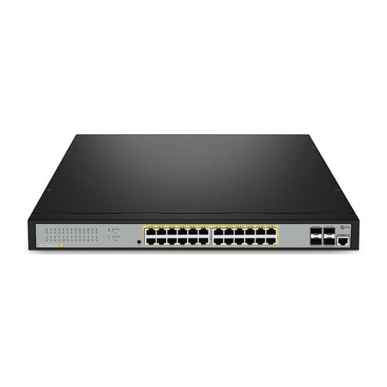
Hardware Overview Front Panel Ports S2805S-24TF-P Console Link/Act CONSOLE Link/Act S2805S-24TF-P PoE+ RESET RESET RJ45 S2805S-24TF Link/Act CONSOLE Link/Act RESET S2805S-24TF RESET RJ45 Console Port/Button Description Press down the button for 5 seconds to restore the switch to its Reset original factory default settings. -
Page 4: Front Panel Leds
Front Panel LEDs S2805S-24TF-P SYS Link/Act Link/Act CONSOLE Link/Act S2805S-24TF-P PoE+ RESET Link/Act S2805S-24TF Link/Act Link/Act CONSOLE Link/Act RESET S2805S-24TF State Description Off Power Off Solid green Power On Off System not started. System is starting or the system starts Blinking green successfully. -
Page 5: Back Panel
Note: Only S2805S-24TF-P has PoE status indicators. Back Panel S2805S-24TF-P Grounding Terminal 100-240V AC 50/60Hz AC Power Connector S2805S-24TF Grounding Terminal 100-240V AC 50/60Hz AC Power Connector Installation Requirements Before you begin the installation, make sure that you have the followings: Phillips screwdriver. -
Page 6: Site Environment
Site Environment: Do not operate it in an area that exceeds an ambient temperature of 50°C. The installation site must be well ventilated. Ensure that there is adequate air flow around the switch. Be sure that the switch is level and stable to avoid any hazardous conditions. Do not install the equipment in a dusty environment. -
Page 7: Rack Mounting
Rack Mounting 1. Fix the mounting brackets to the two sides of the switch with supplied M3 screws. 2. Attach the switch to the rack with four M6 screws and cage nuts. -
Page 8: Grounding The Switch
Grounding the Switch 0 H z V A C 5 0 /6 1 0 0 -2 4 0 1. Connect one end of the grounding cable to a proper earth ground, such as the rack in which the switch is mounted. 2. -
Page 9: Connecting The Power
Connecting the Power 0 H z V A C 5 0 /6 1 0 0 -2 4 0 1. Plug the AC power cord into the power port on the back panel of the switch. 2. Connect the other end of the power cord to an AC power source. WARNING: Do not connect power cable while the power is on. -
Page 10: Connecting The Sfp Ports
Connecting the RJ45 Ports 1. Connect an Ethernet cable to a RJ45 port of IP cameras, IP telephone, Access Points (AP), or other network devices. 2. Connect the other end of the Ethernet cable to the RJ45 port of the switch. Connecting the SFP Ports 1. -
Page 11: Configuring The Switch
Configuring the Switch Configuring the Switch via the Web-based Interface Step 1: Connect the computer to any RJ45 port of the switch with the network cable. Step 2: Set the IP address of the computer to 192.168.1.x. (“x” is any number from 2 to 254.) Internet Protocol Version 4 ( TCP/IPv4) Proper ties General You can get IP settings assigned automatically if your network... -
Page 12: Troubleshooting
RJ45 port doesn’t connect or it is erroneous in receiving/transmitting data. 1. Replace the twisted pair cable. 2. Check that whether the port configuration has the common working mode with the connected switch. Online Resources Download https://www.fs.com/products_support.html Help Center https://www.fs.com/service/fs_support.html Contact Us https://www.fs.com/contact_us.html... -
Page 13: Product Warranty
Product Warranty FS ensures our customers that if there are any damage or faulty items due to our workmanship, we will offer a free return within 1 month from the day you receive your goods. This excludes any custom made items or tailored solutions. - Page 14 Einführung Vielen Dank, dass Sie sich für Managed Switches der S2805S-Serie entschieden haben. Diese Anleitung soll Sie mit dem Aufbau der Switches vertraut machen und beschreibt, wie Sie die Switches in Ihrem Netzwerk einsetzen. Link/Act CONSOLE Link/Act RESET S2805S-24TF-P PoE+ S2805S-24TF-P Link/Act CONSOLE...
- Page 15 Hardware-Übersicht Anschlüsse an der Vorderseite S2805S-24TF-P Console Link/Act CONSOLE Link/Act S2805S-24TF-P PoE+ RESET RESET RJ45 S2805S-24TF Link/Act CONSOLE Link/Act RESET S2805S-24TF RESET RJ45 Console Beschreibung Port/Taste Halten Sie die Taste 5 Sekunden lang gedrückt, um den Switch auf Reset seine ursprünglichen Werkseinstellungen zurückzusetzen. 100/1000Mbps SFP Port Zum Überwachen und Konfigurieren des Switches.
-
Page 16: Leds An Der Vorderseite
LEDs an der Vorderseite S2805S-24TF-P SYS Link/Act Link/Act CONSOLE Link/Act RESET S2805S-24TF-P PoE+ Link/Act S2805S-24TF Link/Act Link/Act CONSOLE Link/Act RESET S2805S-24TF Status Beschreibung Ausschalten. Durchgehend Grün Einschalten. System ist nicht gestartet. Das System wird gestartet oder das System Blinkt Grün startet erfolgreich. - Page 17 HINWEIS: Nur S2805S-24TF-P verfügt über PoE-Statusanzeigen. Rückseite S2805S-24TF-P Erdungsklemme 100-240V AC 50/60Hz AC-Netzanschluss S2805S-24T4F Erdungsklemme 100-240V AC 50/60Hz AC-Netzanschluss Installationsvoraussetzungen Bevor Sie mit der Installation beginnen, vergewissern Sie sich, dass Sie über die folgenden Dinge verfügen: Kreuzschlitzschraubendreher. Ein 19"-Rack in Standardgröße mit einer Mindesthöhe von 1 HE. RJ-45-Ethernet-Kabel der Kategorie 5e oder höher, Glasfaserkabel und Konsolenkabel für den Anschluss von Netzwerkgeräten.
-
Page 18: Montage Des Switches
Standortumgebung: Betreiben Sie das Gerät nicht in einem Bereich, in dem die Umgebungstemperatur 50°C übersteigt. Der Installationsort muss gut belüftet sein. Stellen Sie sicher, dass um den Switch herum ein ausreichender Luftstrom herrscht. Achten Sie darauf, dass der Switch eben und stabil steht, um gefährliche Bedingungen zu vermeiden. - Page 19 Rack-Montage 1. Befestigen Sie die Montagehalterungen mit den mitgelieferten M3-Schrauben an den beiden Seiten des Switches. 2. Befestigen Sie den Switch mit vier M6-Schrauben und Käfigmuttern am Rack.
- Page 20 Erdung des Switches 0 H z V A C 5 0 /6 1 0 0 -2 4 0 1. Schließen Sie ein Ende des Erdungskabels an eine geeignete Erdung an, z. B. an das Rack, in dem der Switch montiert ist. 2.
-
Page 21: Anschließen Der Stromversorgung
Anschließen der Stromversorgung 0 H z V A C 5 0 /6 1 0 0 -2 4 0 1. Stecken Sie das Netzkabel in den Netzanschluss an der Rückseite des Switches. 2. Schließen Sie das andere Ende des Netzkabels an eine Netzstromquelle an. WARNUNG: Schließen Sie das Netzkabel nicht an, während das Gerät eingeschaltet ist. - Page 22 Anschließen der RJ45-Ports 1. Schließen Sie ein Ethernet-Kabel an einen RJ45-Port von IP-Kameras, IP-Telefonen, Access Points (AP) oder anderen Netzwerkgeräten an. 2. Schließen Sie das andere Ende des Ethernet-Kabels an den RJ45-Port des Switches an. Anschließen der SFP-Ports 1. Stecken Sie einen kompatiblen SFP-Transceiver in den SFP-Port. 2.
- Page 23 Konfigurieren des Switches Konfigurieren des Switches über die webbasierte Schnittstelle Schritt 1: Schließen Sie den Computer über das Netzwerkkabel an einen beliebigen RJ45-Port des Switches an. Schritt 2: Stellen Sie die IP-Adresse des Computers auf 192.168.1.x ein. ("x" ist eine beliebige Zahl zwischen 2 und 254.) Internet Protocol Version 4 ( TCP/IPv4) Proper ties General...
-
Page 24: Fehlersuche
4. Versuchen Sie, das Kabel des Switches zu schleifen (Loop). Der RJ45-Port lässt sich nicht anschließen oder empfängt/überträgt Daten fehlerhaft. 1. Tauschen Sie das Twisted-Pair-Kabel aus. 2. Prüfen Sie, ob die Anschlusskonfiguration mit dem angeschlossenen Switch übereinstimmt. Online Ressourcen Download https://www.fs.com/de/products_support.html Hilfecenter https://www.fs.com/de/service/fs_support.html Kontakt https://www.fs.com/de/contact_us.html... - Page 25 Produktgarantie FS garantiert seinen Kunden, dass wir im Falle von Schäden oder fehlerhaften Artikeln, die auf unsere Verarbeitung zurückzuführen sind, eine kostenlose Rückgabe innerhalb von 1 Monat nach Erhalt der Ware anbieten. Dies gilt nicht für Sonderanfertigungen oder maßgeschneiderte Lösungen.
- Page 26 Introduction Nous vous remercions d'avoir choisi les Switchs Manageables de la Série S2805S. Ce guide est conçu afin de vous familiariser avec la configuration du switch et décrit comment procéder à son déploiement. Link/Act CONSOLE Link/Act S2805S-24TF-P PoE+ RESET S2805S-24TF-P Link/Act CONSOLE Link/Act...
-
Page 27: Aperçu Du Matériel
Aperçu du Matériel Ports du Panneau Frontal S2805S-24TF-P Console Link/Act CONSOLE Link/Act S2805S-24TF-P PoE+ RESET RESET RJ45 S2805S-24TF Link/Act CONSOLE Link/Act RESET S2805S-24TF RESET RJ45 Console Port/Bouton Description Appuyez sur le bouton pendant 5 secondes pour rétablir les Reset paramètres d'usine par défaut. Port SFP 100/1000Mbps Pour la surveillance et la configuration du Switch. - Page 28 LED du Panneau Frontal S2805S-24TF-P SYS Link/Act Link/Act CONSOLE Link/Act RESET S2805S-24TF-P PoE+ Link/Act S2805S-24TF Link/Act Link/Act CONSOLE Link/Act RESET S2805S-24TF Statut Description Éteint Appareil Éteint. Vert Appareil Allumé. Éteint Le système n'a pas démarré. Le système est en cours de démarrage ou il a été Vert Clignotant lancé...
-
Page 29: Panneau Arrière
NOTE : Seul le S2805S-24TF-P possède des indicateurs d'état PoE. Panneau Arrière S2805S-24TF-P Terminal Mis à la Terre 100-240V AC 50/60Hz Connecteur d'Alimentation AC S2805S-24T4F Terminal Mis à la Terre 100-240V AC 50/60Hz Connecteur d'Alimentation AC Exigences d’Installation Avant de commencer l'installation, assurez-vous que vous disposez des éléments suivants : Tournevis phillips. - Page 30 Site d’Installation : Ne pas installer l'appareil dans un endroit où la température ambiante dépasse 50°C. Le site d'installation doit être bien ventilé. Veillez à ce qu'il y ait une circulation d'air suffisante autour du switch. Assurez-vous que le switch est à niveau et stable pour éviter tout risque. Ne pas installer l'équipement dans un environnement poussiéreux.
-
Page 31: Montage En Rack
Montage en Rack 1. Fixez les supports de montage aux deux côtés du switch à l'aide des vis M3 fournies. 2. Fixez le switch au rack à l'aide de quatre vis M6 et d'écrous à cage. - Page 32 Mise à la Terre du Switch 0 H z V A C 5 0 /6 1 0 0 -2 4 0 1.Connectez une extrémité du câble de mise à la terre à une mise à la terre appropriée, telle que le rack dans lequel le switch est installé.
-
Page 33: Connexion De L'alimentation
Connexion de l’Alimentation 0 H z V A C 5 0 /6 1 0 0 -2 4 0 1. Branchez le câble d'alimentation CA dans le port d'alimentation situé sur le panneau arrière du switch. 2. Connectez l'autre extrémité du câble d'alimentation à une source de courant alternatif. AVERTISSEMENT : Ne pas brancher le câble d'alimentation lorsque l'appareil est sous tension. - Page 34 Connexion des Ports RJ45 1. Connectez un câble Ethernet au port RJ45 des caméras IP, du téléphone IP, des Points d'Accès (AP) ou d'autres périphériques réseau. 2. Connectez l'autre extrémité du câble Ethernet au port RJ45 du switch. Connexion des Ports SFP 1.
- Page 35 Configuration du Switch Configurez le Switch via Interface Basée sur Web Étape 1 : Connectez l'ordinateur à n'importe quel port RJ45 du switch avec le câble réseau. Étape 2 : Définissez l'adresse IP de l'ordinateur sur 192.168.1.x. ("x" est un nombre quelconque compris entre 2 et 254).
-
Page 36: Dépannage
Le port RJ45 ne se connecte pas ou ne reçoit/transmet pas correctement les données. 1. Remplacez le câble à paire torsadée. 2. Vérifiez que la configuration du port a le même mode de fonctionnement que le switch connecté. Information en Ligne Téléchargez https://www.fs.com/fr/products_support.html Centre d’assistance https://www.fs.com/fr/service/fs_support.html Contactez-nous https://www.fs.com/fr/contact_us.html... -
Page 37: Garantie Du Produit
Garantie du Produit FS garantit à ses clients qu'en cas de dommages ou d'articles défectueux dus à notre fabrication, nous offrons un retour gratuit dans un délai d'un mois à compter de la date de réception de la marchandise. Ceci exclut les articles fabriqués sur mesure ou les solutions personnalisées. -
Page 38: Compliance Information
Responsible party (only for FCC matter) FS.COM Inc. 380 Centerpoint Blvd, New Castle, DE 19720, United States https://www.fs.com UKCA Hereby, FS.COM Innovation Ltd declares that this device is in compliance with the Directive SI 2016 No. 1091 and SI 2016 No. 1101... - Page 39 Die FS.COM GmbH erklärt hiermit, dass dieses Gerät mit der Richtlinie 2014/30/EU und 2014/35/EU konform ist. Eine Kopie der EU-Konformitätserklärung finden Sie unter www.fs.com/de/company/quality_control.html. FS.COM GmbH déclare par la présente que cet appareil est conforme à la Directive 2014/30/UE et 2014/35/UE. Une copie de la Déclaration UE de Conformité est disponible sur https://www.fs.com/fr/company/quality_control.html FS.COM LIMITED...
- Page 40 Q.C. PASSED Copyright © 2022 FS.COM All Rights Reserved.
Need help?
Do you have a question about the S2805S Series and is the answer not in the manual?
Questions and answers