
Related Manuals for Vecow EAC-6000


Summary of Contents for Vecow EAC-6000
- Page 1 USER USER EAC-6000 Manual Manual NVIDIA ® Jetson Orin ™ NX Edge AI Computing System 6 GigE LAN with 4 PoE , 4 GMSL2, 3 USB 3.1, -25°C to 70°C Operation 1.0.0 Edition 20240401...
- Page 2 Record of Revision Version Date Remark Page Description 1.00 2024/04/01 Official Release ©Vecow EAC-6000 User Manual...
- Page 3 This manual is released by Vecow Co., Ltd. for reference purpose only. All product offerings and specifications are subject to change without prior notice. It does not represent commitment of Vecow Co., Ltd. Vecow shall not be liable for direct, indirect, special, incidental, or consequential damages arising out of the use of the product or documentation or any infringements upon the rights of third parties, which may result from such use.
- Page 4 Order Information Part Number Description EAC-6000, NVIDIA Jetson Orin NX, with On-board 8GB RAM, EAC-6000-R08-S*** NVMe SSD, 2 GigE LAN, 3 USB 3.1, 2 COM, 7 GPIO, 4 M.2, 2 SIM, -25°C to 70°C EAC-6000, NVIDIA Jetson Orin NX, with On-board 16GB RAM, EAC-6000-R16-S*** NVMe SSD, 2 GigE LAN, 3 USB 3.1, 2 COM, 7 GPIO, 4 M.2, 2...
- Page 5 Terminal Block, Wide Temperature -30°C to +70°C DIN-RAIL DIN Rail Kit GMSL Camera Kit GMSL Camera with Fakra-Z Connector 5G Module 5G Module with Antenna 4G Module 4G/GPS Module with Antenna WiFi & Bluetooth WiFi & Bluetooth Module with Antenna ©Vecow EAC-6000 User Manual...
-
Page 6: Table Of Contents
2.3 Main Board Expansion Connectors 2.5 Main Board Jumper / Switch Settings 2.6 Ignition Control CHAPTER 3 SYSTEM SETUP 3.1 How to Open Your EAC-6000/EAC-6100/EAC-6200 37 3.2 Installing Nano SIM Card 3.3 Installing Micro SD Card 3.4 Installing M.2 3.5 Installing Antenna Cable 3.6 Mounting Your EAC-6000/EAC-6100/EAC-6200... - Page 7 CHAPTER 4 SOFTWARE SETUP 4.1 Peripheral Interface Guide 4.2 Flash image to Your EAC-6000/6100/6200 4.3 Install the JetPack Package 4.4 Software Ignition Control APPENDIX A : Power Consumption APPENDIX B : Supported Module List ©Vecow EAC-6000 User Manual...
-
Page 8: Chapter 1 General Introduction
GENERAL INTRODUCTION 1.1 Overview The Vecow EAC-6000 Series is an Arm-based Edge AI Computing System. ® Powered by the by NVIDIA Jetson Orin™ NX platform, featuring a 1024-core ® NVIDIA Ampere™ architecture GPU with 32 Tensor cores and 8-core Arm ®... -
Page 9: Features
• 1 CAN Bus supports Flexible Data-rate, 7-bit GPIO • DC 9V to 50V wide range power input, Ignition Power Control • Supports 24/7 secure remote monitoring, control, and optional Out-Of-Band management for disaster recovery empowered by Allxon ©Vecow EAC-6000 User Manual GENERAL INTRODUCTION... -
Page 10: Product Specification
1.3 Product Specification 1.3.1 Specifications of EAC-6000 System ® NVIDIA Jetson Orin™ NX System-On-Module ® ® Processor • 8-core Arm Cortex -A78AE v8.2 64-bit CPU ® ® • 1024 NVIDIA CUDA cores and 32 Tensor cores • 16GB : LPDDR5 DRAM Memory •... - Page 11 -40°C to 85°C (-40°F to 185°F) Humidity 5% to 95% Humidity, non-condensing Relative Humidity 95% @ 70°C Shock Operating, MIL-STD-810H, Method 516.8, Procedure I Operating, MIL-STD-810G, Method 514.6, Procedure I, Vibration Category 4 CE, FCC, EN50155, EN50121-3-2 ©Vecow EAC-6000 User Manual GENERAL INTRODUCTION...
-
Page 12: Specifications Of Eac-6100
• 1 Force Recovery Button • 1 Reset Button • 1 Micro USB Console Port Micro USB • 1 Micro USB Recovery Port 2 SIM Card Socket Power, SSD Antenna 10 Antenna for WiFi/4G/5G/LTE/GPRS/UMTS ©Vecow EAC-6000 User Manual GENERAL INTRODUCTION... - Page 13 -40°C to 85°C (-40°F to 185°F) Humidity 5% to 95% Humidity, non-condensing Relative Humidity 95% @ 70°C Shock Operating, MIL-STD-810H, Method 516.8, Procedure I Operating, MIL-STD-810G, Method 514.6, Procedure I, Vibration Category 4 CE, FCC, EN50155, EN50121-3-2 ©Vecow EAC-6000 User Manual GENERAL INTRODUCTION...
-
Page 14: Specifications Of Eac-6200
7-bit GPIO • 1 Power Button Button • 1 Force Recovery Button • 1 Reset Button • 1 Micro USB Console Port Micro USB • 1 Micro USB Recovery Port 2 SIM Card Socket ©Vecow EAC-6000 User Manual GENERAL INTRODUCTION... - Page 15 -40°C to 85°C (-40°F to 185°F) Humidity 5% to 95% Humidity, non-condensing Relative Humidity 95% @ 70°C Shock Operating, MIL-STD-810H, Method 516.8, Procedure I Operating, MIL-STD-810G, Method 514.6, Procedure I, Vibration Category 4 CE, FCC, EN50155, EN50121-3-2 ©Vecow EAC-6000 User Manual GENERAL INTRODUCTION...
-
Page 16: Mechanical Dimension
1.4 Mechanical Dimension 1.4.1 Dimensions of EAC-6000 231.0 (9.09) Unit : mm (inch) 212.0 (8.35) 193.0 (7.60) 1.4.2 Dimensions of EAC-6100 Unit : mm (inch) 231.0 (9.09) 212.0 (8.35) 193.0 (7.60) ©Vecow EAC-6000 User Manual GENERAL INTRODUCTION... -
Page 17: Dimensions Of Eac-6200
1.4.3 Dimensions of EAC-6200 Unit : mm (inch) 231.0 (9.09) 212.0 (8.35) 193.0 (7.60) ©Vecow EAC-6000 User Manual GENERAL INTRODUCTION... -
Page 18: Eac-6000/Eac-6100/Eac-6200
GETTING TO KNOW YOUR EAC-6000/EAC-6100/EAC-6200 2.1 Packing List Item Description EAC-6000/EAC-6100/EAC-6200 Edge AI Computing System (According to the configuration of your order, EAC-6000/ EAC-6100/ EAC-6200 series may contain micro SD and M.2 modules. Please verify these items if necessary.) Item Description Outlook... -
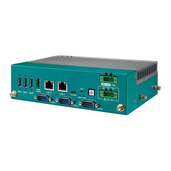
Page 19: Front Panel I/O & Functions
2.2 Front Panel I/O & Functions 2.2.1 Functions of EAC-6000 series In Vecow EAC-6000 series, Most of the I/O connectors are located on the front panels. Most of the general connections to computer devices, such as POWER CON, IGN CON, COM, USB 3.0, LAN (RJ-45), Digital Display Port, GPIO, POWER BUTTON,RESET BUTTON, LED indicators are placed on the front panel. - Page 20 OS. 2.2.1.4 Ethernet Port There are two 8-pin RJ-45 jacks supporting 10/100/1000 Mbps Ethernet connections on the front side of EAC-6000 series. It supports 1000BASE-T gigabit data signals over standard Ethernet Cat 5/Cat 6 cable. LAN Chip...
- Page 21 There is a USB 3.2 Connector connections available supporting up to 10Gb per second data rate in the front side of EAC-6000 series. It also compliant with the requirements of Super Speed (SS), high speed (HS), full speed (FS) and low speed (LS).
- Page 22 There are 2 USB 3.2 Gen1 Connector connections available supporting up to 5Gb per second data rate in the front panel of EAC-6000 series. It is also compliant with the requirements of Speed (SS), High Speed (HS), Full Speed (FS) and Low Speed (LS).
- Page 23 It can be connected by USB (Type A to Micro USB Type) Cable to USB Port of PC, and execute terminal tool, then it will get the system status message. Pin No. Function USB_DATA- USB_DATA+ ©Vecow EAC-6000 User Manual GETTING TO KNOW YOUR EAC-6000/EAC-6100/EAC-6200...
- Page 24 Flash Recov The EAC-6000 USB Recovery mode provides an alternate boot device (USB). In this mode, the system is connected to a host system and boots over USB. This is used when a new image needs to be flashed. USB0 must be available to use as USB Device for USB Recovery Mode.
- Page 25 2.2.1.14 Nano SIM SIM 1 SIM 2 Flash Recov The external Nano SIM card offers wireless communication capability by M.2 key B 4G/5G Card to the system. ©Vecow EAC-6000 User Manual GETTING TO KNOW YOUR EAC-6000/EAC-6100/EAC-6200...
-
Page 26: Main Board Expansion Connectors
2.3.1 TOP View of MB SOM_FAN1 SIM1 SOM_DIMM SIM2 LAN2 LAN1 PWR_CON ATX_PWR_CON M12_LAN2 M12_LAN1 BOT View of MB UART_CN1 OOB_CN1 M2M_CN1 MSB_CN1 DOWNLOAD PORT M2B_CN2 M2E_CN1 JAUDIO1 JUSB1 B2B_CN1 JUART HDD_LED PWR_LED ©Vecow EAC-6000 User Manual GETTING TO KNOW YOUR EAC-6000/EAC-6100/EAC-6200... - Page 27 2.3.1.1 B2B_CN1 Board to Board Connector B2B_CN1 B2B_CN1 connector apply to EAC-6000-CB and EAC-6000-PE board use. Host I/Fs supported MIPI CSI x4 transfer GMSLx4 with Fakra Connector and PCIe x1 transfer 4 GigE with PoE LAN. Definition Definition Definition Definition...
- Page 28 ,2 is RS-232, if you want to change to RS-422 or RS-485, it must change COM mode by DIP SW ( COM1 SW5, COM2 SW4). Pin No. Description COM_DTR COM_CTS COM_TXD COM_RTS COM_RXD COM_DCD ©Vecow EAC-6000 User Manual GETTING TO KNOW YOUR EAC-6000/EAC-6100/EAC-6200...
- Page 29 The connector include 7 bit GPIO with 3.3 power level, it can be set GPI or GPO mode what you want. Pin No. Definition PWR 5V PWR 3.3V GPIO0 GPIO1 GPIO2 GPIO3 GPIO4 GPIO5 GPIO6 ©Vecow EAC-6000 User Manual GETTING TO KNOW YOUR EAC-6000/EAC-6100/EAC-6200...
- Page 30 2.3.1.5 CN6: Reserve I2C/SPI The connector include I2C and SPI bus for reserve application. Pin No. Definition PWR 5V PWR 3.3V I2C1_SCL I2C1_SDA SPI1_SCK SPI1_MISO SPI1_MOSI SPI1_CS0 ©Vecow EAC-6000 User Manual GETTING TO KNOW YOUR EAC-6000/EAC-6100/EAC-6200...
- Page 31 The connector is connected by OOB daughter board, if you want to remote control the system function (Power on / reset or monitor). Definition Definition Definition PWR 5V OOB_SDA PWR 5V OOB_RXD OOB_TXD PSW_NU GPIO0 RST_SW GPIO1 OOB_SCL PWR_DET ©Vecow EAC-6000 User Manual GETTING TO KNOW YOUR EAC-6000/EAC-6100/EAC-6200...
- Page 32 2.3.1.9 M2M_CN1 : M.2 Key M Slot M2B_CN1 The M.2 key M connector is suitable for applications that use Host I/Fs supported PCIe Gen 4 x4, it can be plugged NvME Module card 2280 type. ©Vecow EAC-6000 User Manual GETTING TO KNOW YOUR EAC-6000/EAC-6100/EAC-6200...
- Page 33 2.3.1.12 M2E_CN1 : M.2 key E Slot M2E_CN1 The M.2 key E connector is suitable for applications that use wireless connectivity including Wi-Fi, Bluetooth, NFC of GNSS. Module card types include 2230. ©Vecow EAC-6000 User Manual GETTING TO KNOW YOUR EAC-6000/EAC-6100/EAC-6200...
- Page 34 The connector is connected by OOB cable, it can transfer the debug UART signal to OOB, and it will monitor by Ethernet remote the system status. The UART Signal is switched by SW9. ©Vecow EAC-6000 User Manual GETTING TO KNOW YOUR EAC-6000/EAC-6100/EAC-6200...
-
Page 35: Main Board Jumper / Switch Settings
2.5 Main Board Jumper / Switch Settings 2.5.1.1 Board Top View of EAC-6000 Main Board with Jumper. The figure below is the top view of EAC-5000 series main board which is the main board. It shows the location of the jumpers. - Page 36 2, or 2 and 3. Open Closed Closed 2-3 You may configure your card to match the needs of your application by DIP switch. As below show the DIP switch on and off. ©Vecow EAC-6000 User Manual GETTING TO KNOW YOUR EAC-6000/EAC-6100/EAC-6200...
- Page 37 2.5.1.2 JP3 : SOM_FAN1 Operation Voltage Select Pin No. Definition PWR 5V FAN1PWR PWR 12V 2.5.1.3 JPOE_PWR1: PoE Power On Select Mode JPOE_PWR1 Pin No. Definition 3V3ALW_PWRON 3V3_PWRRUN VCC3_PWRON 2.5.1.4 SW5/SW4 : COM1/COM2 Port Mode Select ©Vecow EAC-6000 User Manual GETTING TO KNOW YOUR EAC-6000/EAC-6100/EAC-6200...
- Page 38 • 1T/1R RS-232 • TX Enable Low Active with Auto Sensing (also mean RS-485 Half Duplex Auto Direction Control) • Check Table 2 for choosing the related resistor ©Vecow EAC-6000 User Manual GETTING TO KNOW YOUR EAC-6000/EAC-6100/EAC-6200...
- Page 39 If the system use the ignition mode, the function can be changed by jumper setting. The default is H/W setting, it can be changed by software, but the jumper must be changed Pin 2-3 short. Pin No. Definition H/W MODE(Default) S/W MODE ©Vecow EAC-6000 User Manual GETTING TO KNOW YOUR EAC-6000/EAC-6100/EAC-6200...
- Page 40 UART and OOB function. The SD card and Audio only option 1 can be used. The UART and OOB only option 1. Please refer as below function Table. Pin No. Definition Status UART_SEL USB_SEL AUDIO On Channel SW8.1 On Channel SW8.2 AUDIO ©Vecow EAC-6000 User Manual GETTING TO KNOW YOUR EAC-6000/EAC-6100/EAC-6200...
- Page 41 2 , 4 OFF CONSOLE 1 , 3 OFF RXD_FT 2 , 4 ON TXD_FT ---------- ---------- TXD_FT ---------- ---------- MICRO_B_RXD ---------- ---------- OOB_TXD ---------- ---------- MICRO_B_TXD ---------- ---------- OOB_RXD ---------- ---------- ©Vecow EAC-6000 User Manual GETTING TO KNOW YOUR EAC-6000/EAC-6100/EAC-6200...
-
Page 42: Ignition Control
2.6.1 Adjust Ignition Control Modes EAC-6000 series provides 16 modes of different power on/off delay periods adjustable via SW6 switch. The default DIP switch is set to 0 in ATX power mode. SW6 : Ignition Control... - Page 43 Please find below the general wiring configuration. For testing purpose, you can refer to the picture blow to simulate ignition signal input controlled by a latching switch. ©Vecow EAC-6000 User Manual GETTING TO KNOW YOUR EAC-6000/EAC-6100/EAC-6200...
-
Page 44: Chapter 3 System Setup
SYSTEM SETUP 3.1 How to Open Your EAC-6000/EAC-6100/EAC-6200 Step 1 Remove four F-M3x4L screws. Step 2 Pick up bottom cover. ©Vecow EAC-6000 User Manual SYSTEM SETUP... -
Page 45: Installing Nano Sim Card
3.2 Installing Nano SIM Card Step 1 Remove two F-M3x4L screw on SD/SIM cover. Step 2 Inserting SIM card, make sure the system power is not plugged. ©Vecow EAC-6000 User Manual SYSTEM SETUP... -
Page 46: Installing Micro Sd Card
3.3 Installing Micro SD Card Step 1 Remove one F-M3x4L screw on SD/SIM cover. Step 2 Inserting SD card. ©Vecow EAC-6000 User Manual SYSTEM SETUP... -
Page 47: Installing
3.4.1 M.2 Key E 2230 Step 1 Install M.2 Key E 2230 into slot and fasten one pan head M3x4L screw. 3.4.2 M.2 Key M 2280 Step 1 Install M.2 Key M 2280 into slot. ©Vecow EAC-6000 User Manual SYSTEM SETUP... - Page 48 Step 2 Install M.2 Key M cover into slot. Step 3 Fasten one pan head M3x4L screw and two F-M3x4L screw. ©Vecow EAC-6000 User Manual SYSTEM SETUP...
- Page 49 3.4.3 M.2 Key B 3042 Step 1 Install transfer bracket into nut and fasten one pan head M3x4L screw. Step 2 Install M.2 Key B 3042 into slot and fasten one pan head M3x4L screw. ©Vecow EAC-6000 User Manual SYSTEM SETUP...
- Page 50 3.4.4 M.2 Key B 3052 Step 1 Fasten one pan head M3x4L screw. ©Vecow EAC-6000 User Manual SYSTEM SETUP...
-
Page 51: Installing Antenna Cable
3.5 Installing Antenna Cable Step 1 Remove the rubber corks on the panel. Step 2 Install the cable with nut and washer indicated. ©Vecow EAC-6000 User Manual SYSTEM SETUP... -
Page 52: Mounting Your Eac-6000/Eac-6100/Eac-6200
3.6 Mounting Your EAC-6000/EAC-6100/EAC-6200 3.6.1 Wall Mount Install wall mount bracket then fasten four pcs F-M3x4L screw. 3.6.2 DIN Rail Mount Install din rail kit then fasten two pcs F-M3x4L screw. ©Vecow EAC-6000 User Manual SYSTEM SETUP... -
Page 53: Chapter 4 Software Setup
4.2 Flash image to Your EAC-6000/6100/6200 Before starting the flashing process, be sure the EAC-6000 is turned off and disconnected from the power. You also need to prepare a host computer running with Ubuntu 18.04 or later. - Page 54 Step 1: Connect the power adapter to the EAC-6000, The EAC-6000 is not yet turned on at this time. Step 2: Connect the Micro USB cable to the “Flash” Port on EAC-6000 and the other end to an available USB port on the host computer. You can connect up to five EAC-6000 devices in recovery mode plugged in the host.
-
Page 55: Install The Jetpack Package
4.3 Install the JetPack Package To install the JetPack package on EAC-6000, you can issue the following commands: $ sudo apt update $ sudo apt install nvidia-jetpack 4.4 Software Ignition Control Vecow provides Ignition Software to control power on/off delay periods. -
Page 56: Appendix A : Power Consumption
Storage M.2 Key M M.2 KEY E Intel AX210NGW LAN 1 1.0 Gbps LAN 2 1.0 Gbps Graphics Output HDMI Power Plan MAXN(16GB, 8GB) Power Source Chroma 62006P-100-25 Test Program Burn-in Test, Stress-ng Test ©Vecow EAC-6000 User Manual Appendix A... - Page 57 Consumption 1.588A 14.29W 2.049A 18.44W 1.168A 14.02W 1.542A 18.50W ® ® 8-core Arm Cortex A78AE v8.2 64-bit 0.663A 15.92W 0.867A 20.82W CPU, up to 2 GHz 0.488A 17.55W 0.624A 22.46W 0.429A 21.43W 0.511A 25.55W ©Vecow EAC-6000 User Manual Appendix A...
-
Page 58: Appendix B : Supported Module List
GPS, Glonass, Beidou and Galileo B.2 Supported Wi-Fi/Bluetooth List Type Model Support Standard SparkLAN_WNFT- IEEE 802.11ac/a/b/g/n M.2 KEY E 237ACN(BT) BT5.0 IEEE 802.11ac/a/b/g/n M.2 KEY E jjPlus JWW6051 BT5.0 IEEE 802.11a/b/e/g/h/i/k/n/r/u/v/w/ac/ax M.2 KEY E Intel AX210NGW BT5.3 ©Vecow EAC-6000 User Manual Appendix B... - Page 59 No part of this publication may be reproduced in any form or by any means, electric, photocopying, or recording, without prior authorization from the publisher. The rights of all the brand names, product names, and trademarks belong to their respective owners. © Vecow Co., Ltd. 2024. All rights reserved.
Need help?
Do you have a question about the EAC-6000 and is the answer not in the manual?
Questions and answers