Kval 700-C Operation And Service Manual
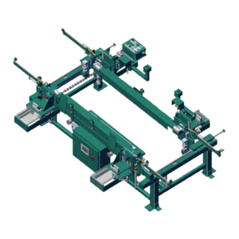
Frame assembler with hand controls
Hide thumbs
Also See for 700-C:
- System reference manual (88 pages) ,
- Service manual (64 pages) ,
- Operation manual (72 pages)

Related Manuals for Kval 700-C


Summary of Contents for Kval 700-C
- Page 1 Operation and Service Manual Published: September 26, 2022 Innovation, Quality & Honesty 700-C Frame Assembler With Hand Controls...
-
Page 2: Contacting Kval
This Manual is confidential and contains proprietary information and intellectual property of KVAL Inc., and is to be used solely by Customer as an operating manual for KVAL Inc. machines. Neither this Manual nor any of the information contained herein may be reproduced or disclosed under any circumstances without the express written permission of KVAL Inc. - Page 3 Kval Website Learn about Kval, order parts, get information on our array of machines (including new machine releases), learn about our machine software solutions, download machine documentation, view videos of our machines in action, contact all the departments.
- Page 4 KVAL 700-C Operation and Service Manual...
-
Page 5: Table Of Contents
Getting the Door Ready to Process ............2-6 Summary of Hand Control Presses........2-7 Firing Staple Guns and Nailer ..........2-7 End Process.................2-7 Turning the 700-C On and Off ..........2-9 Powering Up the 700-C ................2-9 Powering Down the 700-C..............2-9 Main Control Panel ..............2-10 Width Adjust................ - Page 6 Adjusting Cylinder Retraction Speed: ..........5-4 Troubleshooting Electrical Problems ........5-5 If the Power Stops During Normal Operation ........5-5 Troubleshooting with the Status Light Panel ........5-6 Trouble shooting Table................5-6 Adjusting Limit Switches ............5-8 Troubleshooting Photo Detectors ..........5-9 700-C Operation and Service Manual...
- Page 7 Table of Contents ...............Getting Help from Kval 6-1 CHAPTER 6 Getting Help from KVAL............6-2 KVAL Return and Warranty Policy ............6-3 Send the Item ..................6-3 Acceptance of Return ................6-3 Refund Turnaround Time ..............6-3 Kval Errors ....................6-3 Customer Errors ...................6-3 Shipper Errors..................6-4 Warranty Replacement Parts..............6-4...
-
Page 9: Introduction
The 700-C is adjustable for doors from 18" to 4', wide with a standard length capacity of 6'8" or an optional capacity for 7'0" and 8'0" doors. The 700-C can have up to four staple guns mounted on four corner brackets. -
Page 10: Safety First
Failure to do so can result in damage to equipment and/or seri- ous injury to personnel. Safety Guidelines In addition to the caution and warning labels affixed to the 700-C system, follow the guidelines below to help ensure the safety of equipment and personnel. Guideline... - Page 11 This should be done in accordance with the state and/or federal code requirements. Compliance with Codes KVAL Inc. advises that you request an on-site state safety review of your installa- tion of this machine. This is to ensure conformance to any additional specific and Regulations safety and health regulations which apply in your geographic area.
-
Page 12: Lockout And Tagout Guidelines
O..OFF! Shut off all power sources and isolating devices P..Place lock and tag E..ENERGY: Release stored energy to establish, insure and achieve a zero-energy state R ..Re-check controls and test to ensure they are in the “OFF” position 700-C... -
Page 13: Zero-Energy State To Start-Up To Operating State
Provisions which ensure protection during shift changes when contractor or out- side help is used must also comply with the lock-out/tag-out procedures. Comprehensive lock-out/tag- out may use a gang box or other system to ensure that locks are secure and not removed without autho- rization. 700-C... - Page 14 Remember, lock-out/tag-out procedures work because you are the only one with the key to your lock. Proper lock-out/tag-out can save lives, limbs, and money. Help make your work environment safe for yourself and your fellow workers. Be sure to follow the P-R-OP-E-R lock-out/tag-out procedures, and that those around you do also. 700-C...
-
Page 15: Lockout Tagout Procedure
(see illustration below). b.Disconnect style Electrical Panels: push the red tab to pop it out. Place a padlock through the hole. Place your tag on the padlock, as per the tagout guidelines below. (see illus- tration below). 700-C... -
Page 16: Lockout Tagout Air Supply
The lock and tag can now be removed (only by the person(s) who placed them), and the machine can be re-energized. The tags must be destroyed and the locks and keys returned to the lockout center. 700-C... -
Page 17: Safety Sign-Off Sheet
It is recommended you make a copy of this sheet for new operators. If a copy is Note: needed, you may download a PDF at the website (http:// KVAL www.KVALinc.com). You may also contact our Service Department at (800) 553-5825 or email at service@KVALinc.com. 1-10 700-C... -
Page 18: Initial Set Up
Initial Set up Initial Set up Your new Kval machine arrives at your plant crated, banded, taped, with painted set collars on all shafts, keeping all of the precision moving parts secure during shipping. To protect against damaging the machine with the forklift, move the machine as close as possible to the area where it will be stationed before removing it from the crate Use caution when removing the machine from the crate. -
Page 19: Operation
Operation CHAPTER 2 700-C... -
Page 20: Machine Tour
Machine Tour Machine Tour Feed Direction Right Hand Movable Side Main Control Panel Right Hand Fixed Side Infeed Movable Left Hand Fence Movable Side Fixed Fence Touch Screen Outfeed Left Hand Fixed Side 700-C... -
Page 21: About The Electrical Box
About the Electrical Box The main electrical power is connected to the disconnect, located in the large electrical panel. The 700-C requires 110 Volt AC. Typically this voltage is pulled from the previous machine. Refer to the plant layout diagram from more information. -
Page 22: Quick Start
See “Width Adjust” on page 2-11. See “Length Adjust (Option D)” on page 2-13. Load the Door into the Machine Power up the 700-C. See “Powering Up the 700-C” on page 2-9. Select the See “Main Control Jamb Type. Panel” on page 2-10. -
Page 23: Getting The Door Ready To Process
Pull in the door. Swing the hinge jamb down. Getting the Door Ready to Process The 700-C uses Dual Hand Controls to secure and process the door the door. The controls are located next to the Main Control Panel. Dual Hand Controls Note: Both Hand Controls must be maintained to operate the machine. -
Page 24: Summary Of Hand Control Presses
Hand Controls or Select the Return to Start Reset Button Press the Hand Controls to unclamp. Press the Hand Controls or Select the button. Reset (Returns machine to start position) (See “Control Panel” on page 2-24.) RESET Unclamp and Reset 700-C... -
Page 25: Turning The 700-C On And Off
Turn the Control Circuit switch to the OFF position. This kills power to the machine. All status lights should be off. Kval also recommends that you turn the switch on the electrical cabinet to OFF; this helps reduce possible damage resulting from power surges from electrical storm.s. -
Page 26: Main Control Panel
• Control Circuit: Turns power on and off tho the machine. • Machine Power: Start or Stop the machine operat- ing system. • Reset 700-C: Returns the machine to the first sequence of operation. • Staple Sequence: Selects one of seven user-pro- grammed staple patterns. -
Page 27: Width Adjust
Width Adjust Width Adjust The following describes adjusting the 700-C to accommodate different door widths. The picture below shows the location of the width adjust system components. Thick Jamb Spacer 1 Movable Fence Measuring Width Adjust Tape button Location Collar “Pickle”... - Page 28 The collar bar has factory positioned collars set for door widths of 18”, 20” 22”, 24”, 26”, 28”, 30”, 32”, 34”, 36”, 42”and 48”. There are two additional collars for user settable positions. 18” 20” 22” 24” 26” 28” 30” 32” 34” 36” 42” 48” Spares 2-12 700-C...
-
Page 29: Length Adjust (Option D)
Length Adjust (Option D) Length Adjust (Option D) The following describes adjusting the 700-C to accommodate different door lengths. There are 2 adjustment end clamps at each end of the machine. Adjust all 4 end clamps. To adjust the end clamps for 6’8”, 7’0”, or 8’0”... -
Page 30: About The Touch Screen Interface
The following is an overview of the touchscreen functions for basic machine operation. The touchscreen includes a Main Screen that includes access to Program Screens and Maintenance Screens. Screen Paths Programming Screen Main Screen Manual Screen Kval Technician use only Diagnostic Screen 700-C 2-15... -
Page 31: About The Main Screen
Located on all screens. Select Reset if machine is paused. machine. The program will stay on the same screen, jamb size will need to be reselected, all air cylinders return to the start positions. 700-C Main Screen FIGURE 3. About the Programming Screen Select the desired Program Button on the Main Screen to jump to this screen. -
Page 32: How To Set Staple Location
When the trigger bar slot count reaches 7 a staple is fired. Then when the trigger bar slot count equals 12 the staple gun would fire. The result would be 3 staples in the jamb at 1/2”, 2 1/4” and 3 1/2”. Staple Locations Staple Gun Jamb Header Jamb Staple Locations 700-C 2-17... -
Page 33: About The Diagnostic Screen
The top line will have the most current routine that is running. If the machine issue can not be resolved, call KVAL Inc. (1-800-553-5825). Have any error code that is displayed, ready to give the KVAL representative. This will aid in troubleshooting and shorten down time. -
Page 35: Maintenance
Maintenance CHAPTER 3 This chapter describes how to maintain the 700-C system. This chapter contains the following informa- tion: • Maintenance schedule.......page 3-2 • Lubrication requirements....page 3-4 700-C... -
Page 36: Maintenance Schedule
Maintenance Maintenance Schedule KVAL recommends the following maintenance schedule to ensure that the machine operates properly. Refer to this section for steps to perform maintenance. Daily Preventive Maintenance Operation Description Blow off dust from the entire machine.Wipe down the outside of the machine with a Clean clean dry cloth. -
Page 37: Lubrication Schedule
Lubrication Schedule Lubrication Schedule KVAL recommends the following lubrication schedule to ensure that the machine operates prop- erly. Type of Recommended Schedule Recommended Assembly Lubrication Type Linear Bearing Pillow Block Bearing Every 250 Hours of Machine Operation Idler Shaft Dura-Lith Grease (KVAL P/N Lube... -
Page 38: Lubrication Requirements
Closed Pillow Block Hub Style Opened Pillow Block parallel perpendicular mount Greasing Approximatively 1 Gram (one pump from grease gun) of Dura-Lith Grease (KVAL P/N: Lube EP-2). Every 250 hours of operation. Pillow Block Bearings FIGURE 3- 1. 700-C... -
Page 39: Flange Bearing Housings
Flange Greasing Housings Bearing Approximatively 1 Gram (one pump from grease gun) of Dura- Lith Grease (KVAL P/N: Lube EP-2). Every 250 hours of oper- ation. Flange Bearings FIGURE 3- 2. Ball Rail Bearing are linear bearings that are attached to positioning rails. In most cases, the bear- Ball Rail Bearings ings are attached to assemblies to move them in the X,Y, or Z direction. - Page 40 Check the lines every week to two weeks. Sight Glass. Check rate: 1 drop for ever Set top valve to 100psi two door cycles. Adjustment Knob Filter Regulator Lubricator Set bottom valve to 90 psi NOTE: The Lubricator is not installed on all machines. 700-C...
-
Page 41: Grease Points
Lubrication Requirements Grease Points Top View 700-C... - Page 42 Maintenance Heads 700-C...
-
Page 43: Theory Of Operation
Theory of Operation CHAPTER 4 700-C... -
Page 44: Clamps And Rollers (Feed System)
There are two sections, one a mirror image of the other. One section is located on the fixed side of the 700-C, the other on the movable side. Each section consists of a set of tandem pneumatic cyl- inders for the main drive, a pneumatic cylinder for wheel assist, a rack and pinion, three levers, three in feed wheels and two out feed wheels. -
Page 45: Tandem Cylinders
* The dual activated control valves are latching. A control voltage pulse of approximately 0.5 seconds to input of the control valve will cause the valve to change state and latch in that state until another con- trol voltage pulse is received. 700-C... -
Page 46: Wheel Assist Cylinder
Position Visual Description PLC Outputs* Both cylinders deactivated Schematic 0” 1.5” cylinder activated Schematic 1.5” 2.5” cylinder activated Schematic 2.5” Both 1.5” and 2.2” cylin- Schematic 3.7” ders activated 1.5”, 2.2” plus wheels assist Schematic 3.7” Extended cylinders activated 700-C... -
Page 47: Staple Guns
The staple guns inserts staples into the desired locations in the door frame. There are four staple guns. Two on the fixed side and two on the movable side of the 700-C labeled Right Hand-Movable Side, Left Hand-Movable Side, Right Hand-Fixed Side, Left Hand-Fixed Side (see illustration above). Each staple gun assembly consists of a staple gun, a control valve, an air cylinder coupled to an air over oil cylinder and a through beam with a trigger bar. -
Page 48: Staple Gun Horizontal Positioning
The two control valves are located in the main valve bank. The two oil canisters are located on the lower frame rail, one at each end of the 700-C. The staple gun transport cylinders and oil flow regulators are located under the four staple gun carriages. - Page 49 Through Beam the four staple gun carriage. Each through beam circuit consists of an emitter, a receiver and a trigger bar all of which are mounted to the staple gun carriages See illus- tration at right. 700-C...
- Page 50 As the receiver and emitter move down the trigger bar the light sensor outputs a Low for every slot in the trigger bar. The “Lows” are counted by the PLC. See the illustration at right. Emitter And Receiver 700-C...
- Page 51 Slot 17 4 3/4” Slot 18 5” Slot 19 5 1/4” Slot 20 5 1/2” Slot 21 5 3/4” Slot 22 6” Slot 23 6 1/4” Slot 24 6 1/2” Slot 25 6 3/4” Slot 26 7” Slot 27 7 1/4” 700-C...
-
Page 53: Troubleshooting
Troubleshooting CHAPTER 5 700-C... -
Page 54: Get Live Technical Help
Troubleshooting Get Live Technical Help KVAL's Support Team is able to work remotely with your maintenance staff or contractor to diag- nose and troubleshoot machinery issues. To get started, please create a support ticket on-line. Call (800)-553-5825 or start a support ticket on line: https://www.kvalinc.com/support. -
Page 55: Troubleshooting The Air Cylinders
If the valve is not receiving an electrical signal, for instructions. It might be necessary to call in a specialist or check with KVAL customer service at 1-800-553-5825. If an Air Leak is coming from an exhaust port on the solenoid air bank:... -
Page 56: Adjusting Cylinder Extension Speed
When the air leak stops or weakens it usually means that one or more of the cylinders that the solenoid is operating are faulty. Adjusting Cylinder Extension Speed: Adjusting Cylinder Retraction Speed: 700-C... -
Page 57: Troubleshooting Electrical Problems
For more information on the limit switch specifications, see the manu- facturer’s information. For limit switch adjustment procedures, refer to. If a solenoid valve is suspected, and not cleared in the air checks section (see), it can be electrically jumped to check operation. 700-C... -
Page 58: Troubleshooting With The Status Light Panel
Control Trans- former, replace the Control Transformer. If there is power at the Control Transformer, check the wiring of the black and white wire going from the Control Transformer to the 110 VAC Terminal Strip. 700-C... - Page 59 24VDC Home the 700-C Check between DC+ and DC- for 24VDC. If no DC voltage, disconnect the + Brown/Red and - Blue/Black wires from the 24VDC power supply and check for DC voltage where those wires were disconnected.
-
Page 60: Adjusting Limit Switches
If the arm is moved to the full extent of its travel and you do not hear the limit switch “click”, the switch needs to be adjusted. Use the set screw on the limit switch arm and adjust the arm to activate at the desired degree of rotation (see illustrations below). Examples of Limit Switches: 700-C... -
Page 61: Troubleshooting Photo Detectors
24VDC to PLC. If no object is sensed the Photo Eye sends a 0VDC to the PLC. If the photo detector is dirty, it will falsely sense the presence of a door, or other obstruction, and stop the machine operation. If a suspected Photo Detector is clean check for the proper DC Voltage. 700-C... - Page 62 Troubleshooting 5-10 700-C...
-
Page 63: Getting Help From Kval
Getting Help from Kval CHAPTER 6 700-C... - Page 64 Getting Help from Kval Getting Help from KVAL Before you seek help, first try the troubleshooting procedures. Follow the procedures below. If you are unable to resolve the problem: Locate the machine’s Specification Plate and record the serial number, 3 phase volts, electrical print number, and air print number.
-
Page 65: Kval Return And Warranty Policy
Customer Errors If the item is to be returned due to customer ordering error, the customer must return the item to Kval or the shipper of origin at its expense. A 15% restocking fee may apply to manufactured products that are incorrectly ordered by the customer, or if the manufactured part is returned due to a service related inquiry. -
Page 66: Shipper Errors
Shipper Errors Kval recommends the customer insure return shipments if there is any doubt that the product will be accepted in sale- able condition at the Kval warehouse. Occasionally, UPS or FedEx will damage a package, lose a shipment, or send an item to the wrong address. - Page 68 Customer Service Contacting KVAL Phone and Fax: Mailing address: In the U.S and Canada, call (800) 553-5825 or fax Customer Support Department (707) 762-0485 Kval Incorporated Outside the U.S. and Canada, call (707) 762-7367 825 Petaluma Boulevard South or fax (707) 762-0485 Petaluma, CA 94952 Email: service@kvalinc.com...
Need help?
Do you have a question about the 700-C and is the answer not in the manual?
Questions and answers