
Related Manuals for Kval 700-DC


Summary of Contents for Kval 700-DC
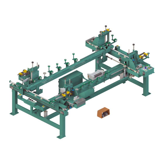
- Page 1 Operation and Service Manual Published: April 15, 2022 Innovation, Quality & Honesty 700-DC Frame Assembler...
- Page 2 6:30 AM to 1:30 PM Pacific Standard Time, Friday Parts & Service Sales: 6:30 AM to 4:00 PM Pacific Standard Time, Monday through Thursday 6:30 AM to 1:30 PM Pacific Standard Time, Friday (Other sales related inquiries: http://www.kvalinc.com) • Email: service@kvalinc.com Kval 700-DC Operation and Service Manual...
- Page 3 Please email your comments and suggestions for improve- ment to userexperience@kvalinc.com. (NOTE: This is not a customer support email link. For that, please refer to the Customer Service contact information above.) Thank you! http://www.kvalinc.com Kval 700-DC Operation and Service Manual...
- Page 4 Kval 700-DC Operation and Service Manual...
-
Page 5: Table Of Contents
Table of Contents Introduction to the 700-DC Chapter 1 Chapter 1 at a Glance................1-1 Overview of the 700-DC ............1-2 Options Available ..................1-2 About this Manual .................1-4 Safety First!................1-5 Safety Sheet Sign-Off Sheet..............1-5 Safety Terminology of Labels..............1-5 Safety Guidelines..................1-5 Lockout-Tagout Guidelines ............ - Page 6 Process of the Outswing Option ............2-11 Adjusting the Sill Height..............2-11 Sill Assembly Results................2-12 Adjusting Length for an Outswing Door ..........2-13 Powering the 700-DC On and Off..........2-14 Powering Up the 700-DC..............2-14 Powering Down the 700-DC ...............2-15 How to Process a Door............2-16 How to Move Back a Step ..............2-16...
- Page 7 About a Typical Contactor Control ........... 4-2 About Contactor Troubleshooting ............4-3 About Limit Switches ............... 4-4 Troubleshooting Limit Switches ............4-4 Troubleshooting Electrical Problems ........4-5 If the Power Stops During Normal Operation ........4-5 Troubleshooting with the Status Light Panel ......4-7 700-DC Operation and Service Manual...
- Page 8 Table of Contents 700-DC Operation and Service Manual...
-
Page 9: Chapter 1 At A Glance
Getting Help from Kval for help. The section Kval Service Center includes how to get information from the specification plate tor provide to Kval, service center hours, and return procedures A record to track operators that are trained on page 1-18 Safety Sign-Off Sheet the machine. -
Page 10: Overview Of The 700-Dc
Automatic screw-driving assemblies with integral pilot hole drills will be System for Sill mounted on each side of the sill end of the 700-DC for attaching the sill. Number of screws per are controlled via a PLC preset and selector switch for jamb width. - Page 11 Staple Guns Provides the customer with the four(4)required staple-guns and corresponding remote fires necessary for the 700-DC, 700-DP, or 700-DX to operate.If cus- tomer wishes to purchase and ship staple-guns to Kval facility instead, select Option If customer wishes to purchase and ship staple-guns to Kval facility instead of purchasing Option S, that is acceptable.
-
Page 12: About This Manual
Overview of the 700-DC About this Manual This manual is part of a package delivered with the machine line. Integration Package includes the following: includes the following: Operation and Service Manual Chap- Title Description Introduction Descriptions of Machine Line and Safety Information. -
Page 13: Safety First
Training Ensure that all employees who operate this machine are aware of and adhere to all safety precautions posted on the machine and are trained to operate this machine in a safe manner. KVAL 700-DC Operation/Service Manual... - Page 14 Before performing any mainte- nance or repairs on this machine turn off the main air disconnect. Lockout and tagout this connection. See “Lockout Tagout Procedure” on page 1-10. KVAL 700-DC Operation/Service Manual...
- Page 15 This should be done in accordance with applicable state and/or federal code requirements. Laser Warnings On some machines, laser indicators are used to set boundaries. Follow the manufacturers safety precautions. KVAL 700-DC Operation/Service Manual...
- Page 16 Follow Your Company’s Safety Procedures In addition to these safety guidelines. Your company should have on-site and machine specific safety proce- dures to follow. KVAL 700-DC Operation/Service Manual...
-
Page 17: Lockout-Tagout Guidelines
O..OFF! Shut off all power sources and isolating devices P..Place lock and tag E..ENERGY: Release stored energy to a zero-energy state R ..Recheck controls and test to ensure they are in the “OFF” state KVAL 700-DC Operation/Service Manual... -
Page 18: Lockout Tagout Procedure
Turn Switch to the Lock and Tag out Insert Lock into hole. OFF position Note: When multiple people are working on the machine, each person needs to have a lock on the handle in the extra holes provided. KVAL 700-DC Operation/Service Manual 1-10... -
Page 19: Lockout Tagout Air Supply
The lock and tag can now be removed (only by the person(s) who placed them), and the machine can be re-energized. The tags must be destroyed and the locks and keys returned to the lockout center. KVAL 700-DC Operation/Service Manual 1-11... -
Page 20: Zero-Energy To Start-Up
Replace Guards Replace all equipment guards. If part of equipment cannot be properly adjusted after start-up with guard on, contact the Service team. See “Getting Help from Kval” Kval on page 1-14. Check Controls Confirm that all switches are in the “OFF” position. Please be advised that some com- ponents of the machine may start automatically when energy is restored. - Page 21 Be sure to follow the P-R-O- P-E-R lockout/tagout procedures, and that those around you do also. Close the Cage Gate Verify all cage gates are securely closed. Ensure all safety protocols are in effect. KVAL 700-DC Operation/Service Manual 1-13...
-
Page 22: Getting Help From Kval
• Outside the U.S. and Canada, call (707) 762-7367 or fax (707) 762-0485 • Email address is service@Kvalinc.com • Hours: 6:00 AM to 4:00 PM Pacific Standard Time, Monday through Thursday 6:30 AM to 1:30 PM Pacific Standard Time, Friday KVAL 700-DC Operation/Service Manual 1-14... -
Page 23: Kval Return And Warranty Policy
We can only accept items for a return if they are still in their original packaging and in undam- aged, resalable condition. Returns are accepted within 45 days of purchase and with an RMA number issued by Kval Inc. Returns after 45 days of purchase or without a Kval Inc. issued RMA number will not be accepted. -
Page 24: Customer Errors
Kval provides a warranty to products that are deemed defective. Within 30 days of discovery of said defect, please notify Kval, but no more than one (1) year after delivery will the product be covered under Warranty. The repair, replacement, or payment in the manner described above shall be the exclusive remedy of Buyer for breach of Kval’s warranty or for claims based upon failure... - Page 25 Kval Return and Warranty Policy Page Intentionally Left Blank KVAL 700-DC Operation/Service Manual 1-17...
-
Page 26: Safety Sign-Off Sheet
Note: It is recommended you make a copy of this sheet for new operators. If a copy is needed, you may download a PDF at the website (http:// Kval www.Kvalinc.com). You may also contact our Service Department at (800) 553-5825 or email at service@Kvalinc.com. KVAL 700-DC Operation/Service Manual 1-18... -
Page 27: Operation
Description of setting up the for work page 2-6 700-DC Mechanical Set-Up Description powering procedures of the machine page 2-14 Power Operations Running the machine. page 2-16 Quick Start Setting up the stapling routines page 2-20 Touch Screen Interface KVAL 700-DC Operation/Service Manual... -
Page 28: About The 700-Dc
Kval 700-DC door sill that does not extend past the interior side of the door frame. This section identifies the assemblies located on the 700-DC Assemblies on the 700-DC Header Operation Controls Hands Free buttons Width Adjust Fixed RH Gun... -
Page 29: About The Main Control Panel
Enables or Disables the staple seven user-programmed staple patterns. See “How to guns on the Movable Head. Set Staple Location” on page 2-21. for staple program- ming instructions Note: If Staple Sequence 0 is selected no staples will be fired KVAL 700-DC Operation/Service Manual... -
Page 30: About The Sill End Controls
“How to Process a Door” on page 2-16. Left Hands Free Button: Right Hands Free Button: Press Press both Left Hand and both Right Hand and left Hand Right Hand simultaneously to simultaneously to clamp the door clamp the door header. header. KVAL 700-DC Operation/Service Manual... -
Page 31: About The Program Interface
The touch screen program interface is located on the Electrical Box. Staple Patterns are set and stored with this program. The touch screen program interface is located on the Electrical Box. Staple Patterns are set and stored with this program. KVAL 700-DC Operation/Service Manual... -
Page 32: Mechanical Set-Up
The reference collars are set at 18”, 20” 22”, 24”, 26”, 28”, 30”, 32”, 34”, 36”, (Opts 42”and 48”). There are two additional collars for user settable positions. 18” 20” 22” 24” 26” 28” 30” 32” 34” 36” 42” 48” Spares Use the attached tape measure to set the width of the doors. KVAL 700-DC Operation/Service Manual... -
Page 33: About The Width Adjust
Push down the width adjust button. This will cause the pickle forks to extend capturing a collar and lock- ing the position of the movable fence. Pickle Fork (Shown in the extended position) KVAL 700-DC Operation/Service Manual... -
Page 34: About The Length Adjust
Secure pin in the adjustment hole. See the figure below. Note: Option D1 adds a 6’6” setting 6’-8” Setting 8’-0'' Setting 7’-0''Setting Adjustment End Clamps FIGURE 1. KVAL 700-DC Operation/Service Manual... -
Page 35: About The Jamb Height Adjust
Adjust Head Height To adjust to different jamb widths, pull the knob to the right to unlock, move the clamp down until the desired position locked. Height Adjust FIGURE 2. KVAL 700-DC Operation/Service Manual... -
Page 36: Option S: About The Outswing Option
FIGURE 3. Sill Shelf The sill rests on this popup shelf Adjustment Rail Lock/Unlock Bolt Outswing Bolt Setting Inswing Bolt Setting Reference Bolt Shelf Popup Cylinder Part Descriptions for the Sill Shelf Adjusting Assembly FIGURE 4. KVAL 700-DC Operation/Service Manual 2-10... -
Page 37: Process Of The Outswing Option
Outswing Bolt may be adjusted if a little wiggle room is needed. Loosen the Note: Outswing Bolt Outswing bolt, adjust the height and secure it. Do not adjust the reference bolt Outswing Bolt Outswing Sill Adjustment KVAL 700-DC Operation/Service Manual 2-11... -
Page 38: Sill Assembly Results
Process a Door” on page 2-16. Sill Assembly Results Figure 5 shows examples of the inswing and outswing adjustments. Note the height of each Sill Shelf Outswing Sill Adjustment Inswing Sill Adjustment Sill Adjustments FIGURE 5. KVAL 700-DC Operation/Service Manual 2-12... -
Page 39: Adjusting Length For An Outswing Door
To adjust the door length assembly, pull up the spring loaded pin on the both the movable and the fixed side and move it to the appropriate length. Secure pin in the adjustment hole. See the figure below. KVAL 700-DC Operation/Service Manual 2-13... -
Page 40: Powering The 700-Dc On And Off
Powering the 700-DC On and Off Powering the 700-DC On and Off Use the procedures below for powering up and powering down the 700-DC Powering Up the 700-DC Powering up the system includes: • Applying power to the entire system •... -
Page 41: Powering Down The 700-Dc
Powering the 700-DC On and Off Powering Down the 700-DC Powering down the system includes: • Shutting down the control power • Removing power from the entire system Push the button. Stop Turn the to the position. Control Circuit Switch... -
Page 42: How To Process A Door
Note: These switches can be turned off independently or in a pair. in this setting the firing sequences can be verified without firing the sta- ples. 1. Main Panel footprint may vary from machine to machine. KVAL 700-DC Operation/Service Manual 2-16... -
Page 43: Control Sequence Summary
Reset Left (LH) and the Right Hands Free Button. Left Hand or Right Hand Pull in the door; verify the header is clear so the stapler heads can come in. Have a little wiggle room. KVAL 700-DC Operation/Service Manual 2-17... - Page 44 Head End, push both Hand Control Buttons to clamp the Header. Push to Clamp the Header Check Fit Push both Sill Hand Control Buttons(Drops door to lower position). Push to Drop the Door to the Lower Position KVAL 700-DC Operation/Service Manual 2-18...
- Page 45 Control Button to fire all enabled staple guns. Push to Fire the Staple guns Push both Hand Control Buttons (Un-Clamp door.) Push to Un-Clamp the Door Pull out the Door.Note: If changing the hand of the door, repeat Step 1. KVAL 700-DC Operation/Service Manual 2-19...
-
Page 46: About The Touch Screen Interface
Main Screen Sill Head between screens if both staple process are under the same program. Staple Location Sill / Head Screen Toggle Back to Main Screen Program Screen FIGURE 8. KVAL 700-DC Operation/Service Manual 2-20... -
Page 47: How To Set Staple Location
2 1/2” 2 3/4” 3” 3 1/4” 3 1/2” 3 3/4” 4” 4 1/4” 4 1/2” 4 3/4” 5” 5 1/4 5 1/2” 5 3/4” 6” 6 1/4” 6 1/2” 6 3/4” 7” 7 1/4” KVAL 700-DC Operation/Service Manual 2-21... -
Page 48: About The Maintenance Screen
LED 8 Program Not Used Program 0 Not Used Program 1 Program 2 Not Used Not Used Program 3 Not Used Program 4 Not Used Program 5 Program 6 Not Used Not Used Program 7 KVAL 700-DC Operation/Service Manual 2-22... -
Page 49: Description Of The Six Light Panel
Description of the Six Light Panel The six lights on this panel indicate the status of the Commander III system. The Sequence that the lights activate is as follows: Control Power Overload Relay E-Stop Stop Start 24VDC KVAL 700-DC Operation/Service Manual 2-23... - Page 50 Description of the Six Light Panel KVAL 700-DC Operation/Service Manual 2-24...
-
Page 51: Chapter 3 Maintenance
Maintenance CHAPTER 3 This chapter describes preventative maintenance steps for . The content is geared to Kval 700-DC guide technicians to keep a regular maintenance schedule for your machine. Keeping your Kval machine maintained is an important piece for successful operation of your door production Kval process. -
Page 52: Maintenance Schedule
Clean linear bearings and the chrome shaft with a clean dry cloth, then lubricate. Clean Check all air lines & electrical wiring for kinks or rubbing. Check Refill lubricator with an ISO 32 standard hydraulic oil (KVAL part# SYSLUBG) LUBE Six Month Preventive Maintenance Operation Description Wash filter and lubricator bowls with soapy water. -
Page 53: Lubrication Schedule
• AGMA #8 gear lube • MOBILUBE HD 80 W-90 • or equivalent Typical Lucubration Kit KVAL Part Number: LUBEKIT Hydraulic Oil Silicone Spray Grease Gun Extension Adapter Needle EP-2 Multi-FAK Nozzle Grease E Adapter Needle Nozzle KVAL 700-DC Operation/Service Manual... -
Page 54: Lubrication Requirements
Closed Pillow Block Hub Style Opened Pillow Block parallel perpendicular mount Greasing Approximatively 1 Gram (one pump from grease gun) of Dura-Lith Grease (KVAL P/N: Lube EP-2). Every 250 hours of operation. Pillow Block Bearings FIGURE 3-1. KVAL 700-DC Operation/Service Manual... -
Page 55: Grease Locations For The 700-Dc
Grease Locations for the 700-DC Grease Locations for the 700-DC This machine is a powerful electro-mechanical Caution motion control system. If servicing this machine, fol- low the safety guidelines. Failure to do so can result in damage to equipment and/or serious injury to person- nel. -
Page 56: Locations Of Stapler Heads Bearings
Grease Locations for the 700-DC Locations of Stapler Heads Bearings For lubrication schedule information, see “Lubrication Schedule” on page 3-3. Figure 3- 3 shows the bearings located on each head assembly. The bearings are color coded for easy identification. The bearings are located on the bottom side of the heads, some bearings may be Note: difficult to get access to. -
Page 57: Outswing Assembly Greasing Point
Grease Locations for the 700-DC Outswing Assembly Greasing Point For lubrication schedule information, see “Lubrication Schedule” on page 3-3. Figure 3- 4 shows the bearings located on each head assembly. The bearings are color coded for easy identification. Lockout/Tagout. Perform Identify the zerk fittings on the pop up shelf. -
Page 58: Description Of Air Input System
Once you have a steady flow, tighten knob back down until you have one drop per every other cycle. Drop will form at end of cane shaped tube visible inside glass. KVAL 700-DC Operation/Service Manual... -
Page 59: Air Line Without Lubricator
The air input system takes in shop air and supplies clean dry air (CDA). Shop Clean Dry Air (CDA) to Air Blow Off Input Air On- Off Knob Muffler Air Distribution Block Pressure Gauge with adjust Filter (purge) Air Filter without Lubricators FIGURE 3-6. KVAL 700-DC Operation/Service Manual... - Page 60 Description of Air Input System KVAL 700-DC Operation/Service Manual 3-10...
- Page 61 Describes a typical contactor control circuit. page 4-2 About Contactor Control Troubleshooting Limit Switches page 4-4 Limit Switches Includes voltages in the electrical panels, using the page 4-5 Troubleshooting Electrical Status Light panel to troubleshoot Problems KVAL 700-DC Operation/Service Manual...
-
Page 62: About A Typical Contactor Control
Control Circuit Common DC - Control Coil for Thermal OverLoad 120 Vac. Should measure Line Voltage here Motor Schematic Drawing of Contactor and Thermal Overload Block Diagram of a Common Contactor Circuit FIGURE 4- 7. KVAL 700-DC Operation/Service Manual... -
Page 63: About Contactor Troubleshooting
Rerun the machine and verify that motor runs without tripping the circuit. If the same overload keeps tripping, verify condition. Follow circuit path using the E-Drawing as a reference. a.Common issues: Check for bad wire, bad motor, or if load is too great for cur- rent draw. KVAL 700-DC Operation/Service Manual... -
Page 64: About Limit Switches
5 or 20 degrees before the limit switch actuates (Clicks). If the arm is moved to the full extents of its travel and you do not here the limit switch “Click”, the switch needs to be adjusted here is how you adjust it follow the following drawings. KVAL 700-DC Operation/Service Manual... -
Page 65: Troubleshooting Electrical Problems
Observe the disconnect switches. Look for loose or broken wires at the disconnect then at all of the components. Check for continuity of all fuses with an OHM meter. (Fuses need to be removed from the bottom side of the fuse holder before measuring the fuses) KVAL 700-DC Operation/Service Manual... - Page 66 Note: Most electrical problems are related to mechanical malfunction (e.g., stuck motors, jammed chain, blocked photo sensors etc.) Note: If a solenoid valve is suspected, and not cleared in the air checks section, it can be electrically jumped to check operation. KVAL 700-DC Operation/Service Manual...
-
Page 67: Troubleshooting With The Status Light Panel
STEP 4: Stop (Amber) If light is OFF go to item page 4-9. STEP 5: Start (Amber) If light is OFF go to item page 4-10. STEP 6: 24VDC (Green light is OFF go to item page 4-10. KVAL 700-DC Operation/Service Manual... - Page 68 X1 and X2. If no power is measured it is a bad transformer. b.If there is power at X1 and X2, check the other side of the fuse. If now power, replace the fuse. KVAL 700-DC Operation/Service Manual...
- Page 69 Start button. If no voltage, check the Stop button to make sure it is all the way out and not stuck in, then check the contact to make sure it is closed. If still no voltage, check the wiring. KVAL 700-DC Operation/Service Manual...
- Page 70 Check for +24VDC at between any –DC and +DC terminal on the DC Terminal block. Reinstall the (+ 24V positive) wires one by one, checking for +24VDC after installing each. If at any point no voltage is found trace the last reinstalled wire and check for shorts. KVAL 700-DC Operation/Service Manual 4-10...
- Page 72 Customer Service Contacting KVAL Phone and Fax: Mailing address: In the U.S and Canada, call (800) 553-5825 or fax Customer Support Department (707) 762-0485 Kval Incorporated Outside the U.S. and Canada, call (707) 762-7367 825 Petaluma Boulevard South or fax (707) 762-0485 Petaluma, CA 94952 Email: service@kvalinc.com...
Need help?
Do you have a question about the 700-DC and is the answer not in the manual?
Questions and answers