Kval 700-C System Reference Manual
Hide thumbs
Also See for 700-C:
- Service manual (64 pages) ,
- Operation manual (72 pages) ,
- Operation and service manual (68 pages)
Table of Contents
Advertisement
Quick Links
Advertisement
Table of Contents
Troubleshooting

Related Manuals for Kval 700-C


Summary of Contents for Kval 700-C
- Page 1 Innovation, Quality & Honesty 700-C System Reference Published: 3/8/18...
-
Page 3: Contacting Kval
Kval, are intended for use by cus- tomers and employees of Kval, and are not to be copied, used, or disclosed to anyone, in whole or in part, without the express written permission of Kval. For authorization to copy this information, please call Kval Customer Support at (800) 553-5825 or fax (707) 762-0485. - Page 4 700-C...
-
Page 5: Table Of Contents
Machine Tour.......................15 Quick Start......................17 Turning the 700-C On and Off................21 Powering Up the 700-C....................21 Powering Down the 700-C ..................21 Control Panel ......................22 Main Control Panel...................... 22 Remote Control Panel (Optional) ................23 Width Adjust ........................ 24 Length Adjust (Option D)................. - Page 6 If the Power Stops During Normal Operation ............. 52 Troubleshooting with the Status Light Panel ............... 53 Troubleshooting Photo Detectors................57 Touch Screen Troubleshooting ................59 Getting Help from Kval ..................69 Product Return Procedure ..................69 Part Locations .....................71 Control Panel ......................77...
-
Page 7: Introduction
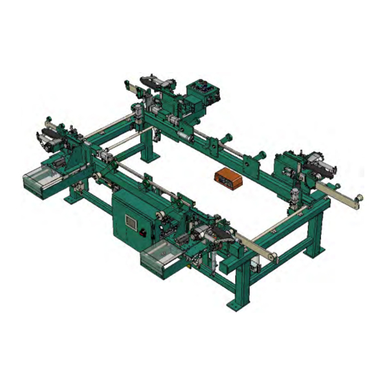
The 700-C is adjustable for doors from 18" to 4', wide with a standard length capacity of 6'8" or an optional capacity for 7'0" and 8'0" doors. The 700-C can have up to four staple guns mounted on four corner brackets. - Page 8 Introduction 700-C...
-
Page 9: Safety First
Failure to do so can result in damage to equipment and/or seri- ous injury to personnel. Safety Guidelines In addition to the caution and warning labels affixed to the 700-C system, follow the guidelines below to help ensure the safety of equipment and personnel. Guideline... -
Page 10: Lock Out Procedure
This policy is required by OSHA regulation 1910.147 and Cal OSHA’S SB198 ruling of July 1991. Use the following lockout procedure to secure the 700-C while it is powered down. During a lockout, disconnect all power and shut off the air supply. Be sure to use the tag-out guidelines noted below. -
Page 11: Lockout And Tagout Guidelines
O..OFF! Shut off all power sources and isolating devices P..Place lock and tag E..ENERGY: Release stored energy to establish, insure and achieve a zero-energy state R ..Re-check controls and test to ensure they are in the “OFF” position 700-C... -
Page 12: Zero-Energy Start-Up
Provisions which ensure protection during shift changes when contractor or out- side help is used must also comply with the lock-out/tag-out procedures. Comprehensive lock-out/tag- 700-C... - Page 13 Proper lock-out/tag-out can save lives, limbs, and money. Help make your work environment safe for yourself and your fellow workers. Be sure to follow the P-R-OP-E-R lock-out/tag-out procedures, and that those around you do also. YOUR LIFE MAY DEPEND ON IT. 700-C...
- Page 14 700-C...
-
Page 15: Initial Set Up
Initial Set up Initial Set up Your new Kval machine arrives at your plant crated, banded, taped, with painted set collars on all shafts, keeping all of the precision moving parts secure during shipping. To protect against damaging the machine with the forklift, move the machine as close as possible to the area where it will be stationed before removing it from the crate Use caution when removing the machine from the crate. - Page 16 INSTALLATION INSTRUCTIONS Drill a ½-inch hole, minimum of 6-inch depth. Clean hole. NOTE: Kval recommends drilling completely through the slab. If in the future the machine needs to be moved, remove the Red Head nut and pound the bolt flush with the floor surface.
-
Page 17: Electrical Connections Overview
The main electrical power is connected to the disconnect, located in the large electrical panel. The 700-C requires 110 Volt AC. Typically this voltage is pulled from the previous machine. Refer to the plant lay- out diagram from more information. - Page 18 700-C...
-
Page 19: Operation Of The 700-C
Operation of the 700-C CHAPTER 2 700-C... - Page 20 Operation of the 700-C 700-C...
-
Page 21: Machine Tour
Machine Tour Machine Tour Feed Direction Right Hand Movable Side Main Control Panel Right Hand Fixed Side Infeed Movable Left Hand Fence Movable Side Fixed Fence Touch Screen Outfeed Left Hand Fixed Side 700-C... - Page 22 700-C...
-
Page 23: Quick Start
Set the door width and length before starting the process. See “Width Adjust” on page 24. See “Length Adjust (Option D)” on page 26. Power up the 700-C. See “Powering Up the 700-C” on page 21. RESET 700-C CONTROL CIRCUIT Select the See “Main Control... - Page 24 First Activate the Foot Pedal Foot Pedal (Option) NOTE: Some 700-C machines have dual switches that must be activated to use the Foot Pedals. switches are located next to the If these switches are not installed bypass these Control Panel.
- Page 25 Quick Start Firing Staple Guns and Nailer For 700-C machines that have dual switches, simultane- ously hold the switch located next to the Control Panel and Press Fire Guns Note: If a hand is taken of the switch during process, there is a 2 second delay before the process can be resumed.
- Page 26 700-C...
-
Page 27: Turning The 700-C On And Off
Turn the CONTROL TRANSFORMER switch to the OFF position. This kills power to the machine. All status lights should be off. Kval also recommends that you turn the disconnect switch on the electrical cabinet to OFF; this helps reduce possible damage resulting from power surges from electrical storms. -
Page 28: Control Panel
Control Panel Main Control Panel • Control Circuit: Turns power on and off tho the machine. • Reset 700-C: Returns the machine to the first RESET 700-C CONTROL CIRCUIT sequence of operation. • Staple Sequence: Selects one of seven user-pro- grammed staple patterns. -
Page 29: Remote Control Panel (Optional)
Note: If Staple Sequence 0 is selected no staples will be fired. ENABLE FIXED ENABLE MOVABLE • Reset 700-C: R3eturns the machine to the first GUSIDE GUNS SIDE GUNS sequence of operation. • Enable Fixed Side Gun: Enables the staple guns on the fixed fence side of the machine. -
Page 30: Width Adjust
Width Adjust The following describes adjusting the 700-C to accommodate different door widths. The picture below shows the location of the width adjust system components. Thick Jamb Spacer 1 Movable Fence Measuring Width Adjust Tape button Location Collar “Pickle” Bars... - Page 31 The collar bar has factory positioned collars set for door widths of 18”, 20” 22”, 24”, 26”, 28”, 30”, 32”, 34”, 36”, 42”and 48”. There are two additional collars for user settable positions. 42” 18” 20” 22” 24” 26” 28” 30” 32” 34” 36” 48” Spares 700-C...
-
Page 32: Length Adjust (Option D)
Length Adjust (Option D) The following describes adjusting the 700-C to accommodate different door lengths. There are 2 adjustment end clamps at each end of the machine. Adjust all 4 end clamps. To adjust the end clamps for 6’8”, 7’0”, or 8’0”... -
Page 33: Touch Screen Interface
Touch Screen Interface Touch Screen Interface The following is an overview of the touchscreen functions for basic machine operation. Main Screen Programing screens Maintenance See See “Programming” See “Maintenance on page 28. (below) Screen” on page 59. 700-C... - Page 34 3/4” grams a staple is fired approximately 1/2” below the top of the jamb in reference to how 1” the jamb is oriented in the 700-C. The programming buttons are used to toggle other staple locations. 1 1/4” For example: 1 1/2”...
-
Page 35: Maintenance
Maintenance CHAPTER 3 This chapter describes how to maintain the 700-C system. This chapter contains the following informa- tion: • Maintenance schedule.......page 30 • Lubrication requirements....page 31 700-C... -
Page 36: Maintenance Schedule
Maintenance Maintenance Schedule KVAL recommends the following maintenance schedule to ensure that the machine operates properly. Refer to this section for steps to perform maintenance. Daily Preventive Maintenance Operation Description Clean Blow off dust from the entire machine.Wipe down the outside of the machine with a clean dry cloth. -
Page 37: Lubrication Schedule
Use Dura-Lith grease: 1 gram every 60 days. Approved Lubrication Products for Lubricators Chevron AW Hydraulic Oil 32 – or KVAL P/N SYSLUBG or G-C lubricants light AW R&O or Mobile DTE 24 or Shell Tellus32 or Gulf Harmony 32. 700-C... - Page 38 Check the lines every week to two weeks. Sight Glass. Check rate: 1 drop for ever Set top valve to 100psi two door cycles. Adjustment Knob Filter Regulator Lubricator Set bottom valve to 90 psi NOTE: The Lubricator is not installed on all machines. 700-C...
-
Page 39: Grease Points
Lubrication Schedule Grease Points Top View 700-C... - Page 40 Maintenance Heads 700-C...
- Page 41 Lubrication Schedule 700-C...
- Page 42 Maintenance 700-C...
-
Page 43: Theory Of Operation
Theory of Operation CHAPTER 4 700-C... -
Page 44: I/O For Normal Operation
Theory of Operation I/O for Normal Operation The following describes the I/O of the 700-C during normal operation: Insert head jamb - No I/O activity. .Insert strike jamb - No I/O activity. Insure head and strike jamb corners meet. Manually pull in door - No I/O activity. - Page 45 6.Press Reset - PLC input I001 PLC output Q010 goes high causing the Out feed Wheels to move up causing the door to move to the position for outfeed. .Manually feed door to next process - No I/O activity. 700-C...
-
Page 46: Clamps And Rollers (Feed System)
There are two sections, one a mirror image of the other. One section is located on the fixed side of the 700-C, the other on the movable side. Each section consists of a set of tandem pneumatic cyl- inders for the main drive, a pneumatic cylinder for wheel assist, a rack and pinion, three levers, three in feed wheels and two out feed wheels. -
Page 47: Tandem Cylinders
* The dual activated control valves are latching. A control voltage pulse of approximately 0.5 seconds to input of the control valve will cause the valve to change state and latch in that state until another con- trol voltage pulse is received. 700-C... -
Page 48: Wheel Assist Cylinder
Both cylinders deactivated Q011 0” Q002 1.5” cylinder activated Q010 1.5” Q002 2.5” cylinder activated Q011 Q001 2.5” Both 1.5” and 2.2” cylinders Q010 3.7” activated Q001 1.5”, 2.2” plus wheels assist Q010 3.7” Extended cylinders activated Q001 Q020 700-C... -
Page 49: Staple Guns
The staple guns inserts staples into the desired locations in the door frame. There are four staple guns. Two on the fixed side and two on the movable side of the 700-C labeled Right Hand-Movable Side, Left Hand-Movable Side, Right Hand-Fixed Side, Left Hand-Fixed Side (see illustration above). Each staple gun assembly consists of a staple gun, a control valve, an air cylinder coupled to an air over oil cylinder and a through beam with a trigger bar. -
Page 50: Staple Gun Horizontal Positing
The two control valves are located in the main valve bank. The two oil canisters are located on the lower frame rail, one at each end of the 700-C. The staple gun transport cylinders and oil flow regulators are located under the four staple gun carriages. - Page 51 Through Beam the four staple gun carriage. Each through beam circuit consists of an emitter, a receiver and a trigger bar all of which are mounted to the staple gun carriages See illus- tration at right. 700-C...
- Page 52 As the receiver and emitter move down the trigger bar the light sensor outputs a Low for every slot in the trigger bar. The “Lows” are counted by the PLC. See the illustration at right. Emitter And Receiver 700-C...
- Page 53 Slot 17 4 3/4” Slot 18 5” Slot 19 5 1/4” Slot 20 5 1/2” Slot 21 5 3/4” Slot 22 6” Slot 23 6 1/4” Slot 24 6 1/2” Slot 25 6 3/4” Slot 26 7” Slot 27 7 1/4” 700-C...
- Page 54 Theory of Operation 700-C...
-
Page 55: Troubleshooting
Troubleshooting CHAPTER 5 700-C... -
Page 56: Troubleshooting The Air Cylinders
If the valve is not receiving an electrical signal, for instructions. It might be necessary to call in a specialist or check with KVAL customer service at 1-800-553-5825. If an Air Leak is coming from an exhaust port on the solenoid air bank:... -
Page 57: Adjusting Cylinder Extension Speed
When the air leak stops or weakens it usually means that one or more of the cylinders that the solenoid is operating are faulty. Adjusting Cylinder Extension Speed: Adjusting Cylinder Retraction Speed: 700-C... -
Page 58: Troubleshooting Electrical Problems
For more information on the limit switch specifications, see the manu- facturer’s information. For limit switch adjustment procedures, refer to. If a solenoid valve is suspected, and not cleared in the air checks section (see), it can be electrically jumped to check operation. 700-C... -
Page 59: Troubleshooting With The Status Light Panel
If one RELAY or more lights are OFF, follow the process below to ascertain the cause. E-STOP 24VDC NOTE: Be sure to proceed down the table, starting with the CONTROL POWER light. 700-C... - Page 60 Start button and hold it in while a second person checks for volt- age between #2 and #7. If there is 110 VAC, replace the ACR relay. If there is no voltage while the button is held in, check the wiring. 700-C...
- Page 61 Troubleshooting Electrical Problems 24VDC Home the Check between DC+ and DC- for 24VDC. If no DC voltage, disconnect the 700-C + Brown/Red and - Blue/Black wires from the 24VDC power supply and (see) check for DC voltage where those wires were disconnected.
- Page 62 If the arm is moved to the full extent of its travel and you do not hear the limit switch “click”, the switch needs to be adjusted. Use the set screw on the limit switch arm and adjust the arm to activate at the desired degree of rotation (see illustrations below). Examples of Limit Switches: 700-C...
-
Page 63: Troubleshooting Photo Detectors
24VDC to PLC. If no object is sensed the Photo Eye sends a 0VDC to the PLC. If the photo detector is dirty, it will falsely sense the presence of a door, or other obstruction, and stop the machine operation. If a suspected Photo Detector is clean check for the proper DC Voltage. 700-C... - Page 64 Troubleshooting 700-C...
-
Page 65: Touch Screen Troubleshooting
Shows status of Enable Fixed Guns switch (SW13 & (OPTIONAL) SW13A): See “Control Panel” on page 77. for switch location. Right header Shows status of Infeed head in place in place limit switch (LS14). See “Moveably Fence - Inside view” on page 75. 700-C... - Page 66 Shows status of the Jamb Width C switch (SW36 & (Optional) SW36A). See “Main Con- trol Panel” on page 77. Jamb Width D Shows status of the Jamb Width D switch (SW37 & (Optional) SW37A). See “Main Con- trol Panel” on page 77. 700-C...
- Page 67 Shows status of Fixed left through beam (THRU011) See “Heads” on page 73. for location. SS-12 Enable movable guns Shows status of Enable Movable Guns switch (SW12 & (OPTIONAL) SW12B):. See “Control Panel” on page 77. for switch location. 700-C...
- Page 68 Shows status of Door in Machine photo eye (PE16). See “Fixed and Movable Fence” on page 71. for location. LS-17 Guns in Shows status of Guns In limit switch (LS17). See “Fixed Fence - Inside view” on page 74. 700-C...
- Page 69 SS-23 Remote Not-8 Note: At present Program Local 8 is not used. SS-25 Metal Sill Not used SS-26 Manual / Auto Shows status of 6’8”/8’0 switch See “Main Control Panel” on page 77. for location. CR-27 Remote hand info Not used 700-C...
- Page 70 Shows status of Staple Sequence switch (SW20,SW21,SW22,SW23) See “Remote Control Panel (Optional)” on page 78. The Staple Sequence switch converts the decimal Staple SS-34 Jamb size B Sequence number to it’s binary equivalent. See “Staple sequence switch truth table” above SS-34 Jamb size C SS-34 Jamb size D 700-C...
- Page 71 Shows status of control valve SV-13 which control SG2 (See “Heads” on page 73.) SV-14 Fire right fixed Shows status of control valve SV-14 which control SG3 (See “Heads” on page 73.) SV-15 Fire left fixed Shows status of control valve SV-15 which control SG4 (See “Heads” on page 73.) 700-C...
- Page 72 Shows status of control valve SV-25 (See “Control Valves” on page 76.) PL-26 No jamb error Shows status of 6’8”/8’0 switch. See “Main Control Panel” on page 77. for location. Q-27 Not used Q-30 Not used Q-31 Not used Q-32 Not used Q-33 Not used 700-C...
- Page 73 Touch Screen Troubleshooting TABLE 14. Title Notes Q-34 Not used Q-35 Not used Q-36 Not used CR-37 OK to feed door in Shows status of PLC output 37 700-C...
- Page 74 700-C...
-
Page 75: Getting Help From Kval
Technical Support business hours are 4:00 AM to 4:30 PM Pacific Standard Time, Monday through Fri- day. Product Return Procedure If you’ve contacted Kval for help and it is determined that a return is necessary, use the procedure below to return the machine or part. Note: Non-Warranty returns are subject to a 15% restocking charge. - Page 76 700-C...
-
Page 77: Part Locations
Part Locations Part Locations Fixed and Movable Fence In Feed FS4 - I004 Seq. Forward FS5 - I005 Seq. Reverse Fixed Movable PE16 - I016 Fence Fence Door In Machine Out Feed Key: Reference Designator - I/O I/O Description 700-C... - Page 78 Outfeed wheels up Outfeed wheels up Q011 - Extend Q011 - Extend Outfeed wheels down Outfeed wheels down PC28 - Q020 PC8 - Q020 Assist Cylinder Assist Cylinder Fixed Movable Fence Fence Out Feed Key: Reference Designator - I/O I/O Description 700-C...
- Page 79 Fixed Side Clamp Movable Side Clamp Junction Box SV3 - Q015 SV2 - Q013 Fire Left Fixed Fire Left Movable SG4 - Q015 SG2 - Q013 Fire Left Fixed Fire Left Movable Key: Reference Designator - I/O I/O Description 700-C...
- Page 80 PC30 - Q034 Head Clamps PC21: (Inner) Q022: Extend 3/4” Cylinder Q021: Retract 3/4” Cylinder LS-15 - I0015 Outfeed head PC23: In Place Q004: Bottom Jamb Clamp PC31 - Q036 Head Clamps (Outer) Key: Reference Designator - I/O I/O Description 700-C...
- Page 81 (Inner) PC22: Q022: Extend 3/4” Cylinder PC10 - Q016 Q021: Retract 3/4” Cylinder Head Clamps (Inner) PC24: Q004: Bottom Jamb Clamp PC12 PC11 - Q016 Manually operated Head Clamps Width Lock (Outer) Key: Reference Designator - I/O I/O Description 700-C...
- Page 82 SV-21 - Q021 SV-23 - Q023 Infeed Wheels Down Retract 3/4” Retract 2” Cylinder Cylinder SV-01 - Q001 Infeed Wheels Up SV-22 - Q022 SV-24 - Q024 Extend 3/4” Extend 2” Cylinder Cylinder Key: Reference Designator - I/O I/O Description 700-C...
-
Page 83: Control Panel
SW24 - I024 SW12 - I012 Enable Movable Guns SELECT LOCAL/REMOTE (OPTIONAL) PB01 - I001 Control Circuit Power Local & Remote Reset RESET 700-C CONTROL CIRCUIT SW30,SW31,SW32,SW33: SW00 - I000 I030: Program Select - Jamb Reg/Split Local Select #1 I031: Program Select -... - Page 84 Remote Control Panel (Optional) SW20,SW21,SW22,SW23: SW1A - I001 Local & Remote Reset I030: Program Select - RESET 700-C STAPLE SEQUENCE Remote Select #1 I031: Program Select - Remote Select #2 SW12A - I012 I032: Program Select - ENABLE FIXED ENABLE MOVABLE...
- Page 85 Part Locations Head Jamb Stapling (Optional) Infeed Outfeed 700-C...
- Page 86 700-C...
- Page 88 Contacting KVAL Customer Service Phone and Fax: Mailing address: In the U.S and Canada, call (800) 553-5825 or fax Customer Support Department (707) 762-0485 Kval Incorporated Outside the U.S. and Canada, call (707) 762-7367 825 Petaluma Boulevard South or fax (707) 762-0485 Petaluma, CA 94952 Email: service@kvalinc.com...
Need help?
Do you have a question about the 700-C and is the answer not in the manual?
Questions and answers