Kval Edge-SS Operation & Service Manual
Hide thumbs
Also See for Edge-SS:
- Service manual (107 pages) ,
- Operation manual (152 pages) ,
- Quick start (2 pages)

Subscribe to Our Youtube Channel
Related Manuals for Kval Edge-SS


Summary of Contents for Kval Edge-SS
- Page 1 Operation/Service Manual Published: July 17 2018 Innovation, Quality & Honesty Edge-SS System...
- Page 2 Proprietary Notice This Manual is confidential and contains proprietary information and intellectual property of KVAL Inc., and is to be used solely by Customer as an operating manual for KVAL Inc. machines. Neither this Manual nor any of the information contained herein may be reproduced or disclosed under any circumstances without the express written permission of KVAL Inc.
- Page 3 KVAL Endeavor System Operation Manual Your Feedback is Welcome: To help us design products that make your job easier and your business more successful, we'd like to gain your perspective about your user experience with our product - that is, the manual, the machinery, the software, etc.
- Page 4 LICENSE. IF YOU DO NOT AGREE TO ALL OF THE TERMS OF THIS LICENSE, THEN DO NOT USE THE KVALCAM SOFTWARE. KVAL, Inc., is the owner of all rights in respect of the software and documentation (referred to as “Licensor”). You are the purchaser of KVAL Machinery operated by the KVALCAM Software are the “Licensee”.
- Page 5 KVAL Edge-SS Operation/Service Manual...
-
Page 6: Table Of Contents
Table of Contents Introduction to the Edge-SS System Chapter 1 Overview of the Edge-SS System ........... 1-2 About this Manual ..............1-4 Safety First!................1-5 Safety Sheet Sign-Off Sheet..............1-5 Safety Terminology of Labels..............1-5 Safety Guidelines..................1-5 Lockout-Tagout Guidelines ............1-9 Follow the P-R-O-P-E-R lockout rule of thumb........1-9 Lockout Tagout Procedure............ - Page 7 Foot Pedal ..................2-15 Emergency Shutdown and Recovery ..........2-15 To Resume Normal Operation after an E-Stop ........2-15 Initial Powering Operations for the Edge-SS Line ....2-16 How to Power Up the Edge-SS Line...........2-16 Description of the Six Light Panel ............2-17 Home the Machine Line..............2-18 How to Power Down the Machine............2-18...
- Page 8 Access to the Calibration Adjustments ..........3-3 Unlock the Calibration (Option).............3-4 Enter a Positive or Negative Number? ..........3-4 Axis Direction for the Edge-SS Front Section........3-5 How to Enter Calibration Data ..........3-6 About Restore Points................3-6 About the Edge-SS Calibration Screen ........3-7 Edge-SS Calibration Screen..............3-7...
- Page 9 Table of Contents System IT Administration Chapter 4 System IT Administration............4-2 About the Edge-SS Line Computer ............4-2 Connections on the PLC...............4-2 Backing up the Computer ..............4-3 About Remote Connection to KVAL Service.........4-3 Maintenance of the Edge-SS Line Chapter 5 Maintenance Schedule ............
- Page 10 Ball Screw Drive Assembly..............5-18 Pulley and Idler Shafts................5-19 Sample of Grease Locations for Edge-SS....... 5-20 Locations of Bearings on the Cutting Head of the Edge-SS....5-21 Deep Drill Bearing Locations (Option) ..........5-21 Description of Air Input System ..........5-22 Air Input with Lubrication ..............5-22 Air Line Without Lubricator ..............5-23...
- Page 11 Important Notice about Adjusting Cylinder Speed ......6-16 Adjusting Cylinder Extend Speed ............6-17 Adjusting Cylinder Retraction Speed ..........6-17 Valve Bank Locations .............. 6-18 Location of Valve Banks on the Edge-SS ...........6-18 Network System Overview............6-19 Connections to Servo Drives ..............6-19 Edge-SS Servo Motor Locations ............6-20 About Switches and Sensors...........
- Page 12 KVAL Edge-SS Line Operation\Service Manual...
- Page 13 This section describes the method to con- page 1-14 Getting Help from KVAL tact the KVAL service center for help. The section includes how to get information from the specification plate tor provide to KVAL, service center hours, and return procedures...
-
Page 14: Overview Of The Edge-Ss System
A Door Touch-off system is used to automatically accurately determine the length of the door from the '0' or the fixed stop on the left end of the Edge-SS. With this system, both left and right hand doors are positioned against the same stop. The machining head automatically adjusts to the correct position based on the door hand selection that is entered. - Page 15 Overview of the Edge-SS System nected to a solid state motion controller. The computer allows an almost limitless number of routing patterns to be stored for instantaneous set-up. Edge: Programming has been developed to automatically generate the most common CNC pro- gramming with graphics screens.
-
Page 16: About This Manual
Chapter 4 System IT Descriptions of the PLC system, Administration and computer system. Chapter 5 Maintenance Maintenance steps for the machine line Chapter 6 Trouble Shoot- Troubleshooting tips and theory of operation. KVAL Operation/Service Manual... -
Page 17: Safety First
See “Safety Sign-Off Sheet” on page 1-19. Safety Terminology of Labels In addition to the nameplate, KVAL machines may have other warning labels or decals that pro- vide safety information to operators. Safety labels should be clearly visible to the operator and must be replaced if missing, damaged, or illegible. - Page 18 All cylinders on machine are under high pressure and can be very dangerous when activated. Before performing any mainte- nance or repairs on this machine turn off the main air disconnect. Lockout and tagout this connection. See “Lockout Tagout Procedure” on page 1-10. KVAL Operation/Service Manual...
- Page 19 This should be done in accordance with applicable state and/or federal code requirements. Laser Warnings On some machines, laser indicators are used to set boundaries. Follow the manufacturers safety precautions. KVAL Operation/Service Manual...
- Page 20 Safety First! Compliance with Codes and Regulations KVAL advises that you request an on-site state safety review of your installation of this machine. This is to ensure conformance to any additional specific safety and health regula- tions which apply in your geographic area.
-
Page 21: Lockout-Tagout Guidelines
O..OFF! Shut off all power sources and isolating devices P..Place lock and tag E..ENERGY: Release stored energy to a zero-energy state R ..Recheck controls and test to ensure they are in the “OFF” state KVAL Operation/Service Manual... -
Page 22: Lockout Tagout Procedure
Turn Switch to the Lock and Tag out Insert Lock into hole. OFF position Note: When multiple people are working on the machine, each person needs to have a lock on the handle in the extra holes provided. KVAL Operation/Service Manual 1-10... -
Page 23: Lockout Tagout Air Supply
The lock and tag can now be removed (only by the person(s) who placed them), and the machine can be re-energized. The tags must be destroyed and the locks and keys returned to the lockout center. KVAL Operation/Service Manual 1-11... -
Page 24: Zero-Energy To Start-Up
Replace Guards Replace all equipment guards. If part of equipment cannot be properly adjusted after start-up with guard on, contact the KVAL Service team. See “Getting Help from KVAL” on page 1-14. Check Controls Confirm that all switches are in the “OFF”... - Page 25 Be sure to follow the P-R-O- P-E-R lockout/tagout procedures, and that those around you do also. Close the Cage Gate Verify all cage gates are securely closed. Ensure all safety protocols are in effect. KVAL Operation/Service Manual 1-13...
-
Page 26: Getting Help From Kval
Ask about this procedure when calling are service team Product Return Procedure If you’ve contacted KVAL for help and it is determined that a return is necessary, use the proce- dure below to return the machine or part. - Page 27 • With what equipment is the unit interfaced? • What was the application? • What was the system environment (temperature, spacing, contaminants, etc.)? Call KVAL customer support for a Return Material Authorization (RMA). When you call: • Have the packing slip or invoice numbers available.
-
Page 28: How To Download The Service Application
Download Application To download the application, go the KVAL website ( http:// www.kvalinc.com At the KVAL website, select the tab. Follow the instruc- Support tions on the Support web page. Click the Download button to download the application that... - Page 29 Session code: An internal number to track this machine. It is auto filled. Your Name Field: Enter your name. The KVAL tech- nician will use this field to identify this machine. Description: Enter machine Serial number and issue.
- Page 30 How to Download the Service Application Page Intentionally Left Blank KVAL Operation/Service Manual 1-18...
-
Page 31: Safety Sign-Off Sheet
Note: It is recommended you make a copy of this sheet for new operators. If a copy is needed, you may download a PDF at the KVAL website (http:// www.kvalinc.com). You may also contact our Service Department at (800) 553- 5825 or email at service@kvalinc.com. - Page 32 Safety Sign-Off Sheet KVAL Operation/Service Manual 1-20...
- Page 33 Inputted values by the user for an intended feature. The input is interpreted by the program and passed through a validation scheme for all machines in a line to determine if the intended cut is capable of being run (see validation). KVAL Operation/Service Manual 2-43...
- Page 34 Each feature has its own validation tests and will fail if the tests for a valid feature are not satisfied. Clicking on a specific test will provide an explanation of the test being performed so that the user can correct the mistake. KVAL Operation/Service Manual 2-44...
- Page 35 Definitions KVAL Operation/Service Manual 2-45...
- Page 36 CHAPTER 2 Operation of the Edge-SS Line This chapter describes components, assemblies, and the user interface of the KVAL Edge-SS Sys- tem. The content is geared to help operators understand the basic operation of the machine. Included are instructions to calibrate the machine and process a door.
-
Page 37: About The Edge-Ss Process
, doors are loaded to be processed, and the area is clear and safe to start production. Homed Actions If needed, set the job parameters from the Edge-SS .See “About the Edge-SS Interface Main Screen Pull door in Screens” on page 2-39 for instructions. -
Page 38: About The Machine Line
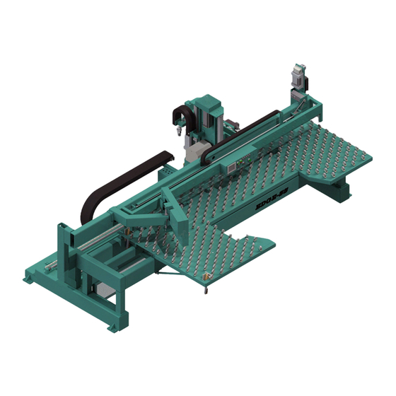
About the Machine Line About the Machine Line The Edge-SS is a computer-controlled router designed to machine architectural doors for hinge pockets, T-strikes, concealed closures, flush bolts, leaf and European hinges, end pivots, as well as edge work for either cylindrical or deep pocket locks. Many customers also use the Edge for re-railing &... -
Page 39: Front View Of The Edge-Ss
Front View of the Edge-SS Front View of the Edge-SS At the front of the machine the operator controls the door through the process. This includes load- ing templates of the cut to be performed, controlling the path of the door, positioning the door, and feeding the door thorough to the next machine. -
Page 40: Edge-Ss Fence, Clamps, Stops
Edge-SS Fence, Clamps, Stops Edge-SS Fence, Clamps, Stops The Door is pressed against the Fence and Stops. After the door is secure, clamp the door with the foot pedal. Door Clamps Door Fence Door Stops Indicator Light The indicator light monitors the process of the cutting routine. The visibility of the light allows observation of the progress of the machining in a factory environment. -
Page 41: About Sensors
About Sensors About Sensors On the Edge-SS, sensors provide input to the PLC as part of the automation of the door cutting process, including feed through, door clamping, and door location. It is important to keep the sen- sors cleaned and aligned to keep the door process running smoothly. There are two classifications of sensors on the Face-SS: Photo Electronic and Inductive Proximity Sensor. -
Page 42: Assemblies On The Main Cutter Head
Toggles the Head for 3 and 0 degree cuts Opt: Chisels X4 Y-Axis Servo Motor Deep Drill Z-Axis Servo Motor Deep Drill: Drills a deep cut Auto Lubricators: Auto lubri- cates the X-Axis Gear and rail. Electronic Node: Connections from the Electrical Panel KVAL Operation/Service Manual... - Page 43 Main Plate Router: Routs the Face plate pocket Deep Mortise Router: Routs a deep pocket. Opt: Chisels X4 Z-Axis Servo Motor Electronic Node: Connections from the Electrical Panel Auto Lubricators: Auto lubri- cates the X-Axis Gear and rail. KVAL Operation/Service Manual...
-
Page 44: About The Feelers
After the door has been fed in to the door stop and clamped, the feelers “feel’ the other end of the door. The location of the stop and the machine encoders are com- bine to calculate the exact length of the door Sensor9 (Feeler) Encoder KVAL Operation/Service Manual... -
Page 45: About Door Thickness Feeler
After the door has been fed in to the door stop and clamped, the feelers lightly tap the face of the door. The feeler and encoder work with the drill location to pro- vide an accurate depth. KVAL Operation/Service Manual 2-10... -
Page 46: Laser Safety Scanners
If the field is broken during cutting the machine will stop. To recover, if the field is broken Push the button on the START MACHINE operator's station. the Machine. 2. Home A Generalized sample of the laser safety Coverage KVAL Operation/Service Manual 2-11... -
Page 47: How To Position A Door For Cutting
Top and Bottom Cuts Use this position for Left Hand Top and Right Hand Bottom Hinge Side Edge Cuts Use this position for Left Hand Hinge and Right Hand Lock KVAL Operation/Service Manual 2-12... -
Page 48: Summary Of The Controls On The Machine Line
• Shows the path of the door mir- rored by the operating template. The right side • Contains the Operator’s Inter- face. Examples Door Placement (Left Side of Screen) KVAL Operation/Service Manual 2-13... -
Page 49: Main Machine Controls
• Puts the machine to sleep. Stop Machine Button: For detailed information about the start-up process, see “Initial Powering Opera- tions for the Edge-SS Line” on page 2-16. Edge-SS Controls Edge Position Lights: Indicates the selected door edge. Edge Toggle: Door edge selection... -
Page 50: Foot Pedal
If an E-Stop is activated, use the following procedure to recover, after the cause of the emergency stop is resolved: De-activate the E-Stop switch by pulling it out. Push the button on the operator's station START MACHINE KVAL Operation/Service Manual 2-15... -
Page 51: Initial Powering Operations For The Edge-Ss Line
Initial Powering Operations for the Edge-SS Line Initial Powering Operations for the Edge-SS Line This section describes how to power up and to power down the Edge-SS Line. Powering up the system includes: • Applying power to the entire system •... -
Page 52: Description Of The Six Light Panel
Initial Powering Operations for the Edge-SS Line Description of the Six Light Panel The six lights on this panel indicate the status of the power-up of the system. Each machine has this panel. The Sequence the lights activate is as follows:... -
Page 53: Home The Machine Line
Initial Powering Operations for the Edge-SS Line Home the Machine Line The Machine Line must go through a homing routine before any operations are performed. The homing routine sets a zero reference from which each machine measures its movement and cut- ting process. -
Page 54: Machine Start Summary
Machine Start Summary Machine Start Summary This is a summary of the start sequence for the Edge-SS Line. These instructions assume that a Door Job has been created to be used in the machining process. To learn more about Door Jobs and Templates, see “About the Libraries Screen”... - Page 55 (accord- 1. DOOR STOP ing to set-up) Position the door. (See “How to position the door for cutting:” Position on page 2-7. Door (after secur- 3. DOOR CLAMP ing the door) button 4. START SEQUENCE KVAL Operation/Service Manual 2-20...
- Page 56 Machine Start Summary If completed for the day, power down the machine. For more information: See “How to Power Up the Edge-SS Line” on page 2-16 Press the located on the Operators Station. Red Stop button, Shut down the operating system, by selecting...
-
Page 57: Summary Of The Kvalcam Interface
Below are screen shots of the operator screens that control the machine. Main Control Includes auto controls, speed control, and sequence controls See “About the Edge-SS Interface Screens” on page 2-39. Manual Servo Control From this screen, move the Cutting Head and Table. - Page 58 Summary of the KvalCAM Interface Tool Config From this screen, set parameters for each tool in the Cutting Head. See “About the Tool Config Tabs” on page 2-46. KVAL Operation/Service Manual 2-23...
-
Page 59: Summary Of The Kvalcam Interface
Below are screen shots of the operator screens that control the machine. Main Control Includes auto controls, speed control, and sequence controls See “About the Edge-SS Main Screen” on page 2-39. Manual Servo Control From this screen, move the Cutting Head and Table. -
Page 60: Status And Log Screens
See “About the Status and Log Screens” on page 2-52. Log Screen From this screen, the feedback codes from the machine. See “About the Status and Log Screens” on page 2-52. KVAL Operation/Service Manual 2-25... -
Page 61: About Machine Status Feedback
Select the tabs to jump to associated Operator’s Screen. The active screen will highlight with a green background KVAL Operation/Service Manual 2-26... -
Page 62: About The Libraries Screen
/templates. Door Job List Door Job Count Template List Template Count Door Job Buttons Template Buttons Screen Shots of Door Job and Templates FIGURE 2-3. KVAL Operation/Service Manual 2-27... -
Page 63: About The Door Job/Template Buttons
Jumps to the Job Create Door jobs Creation Screen using the Features or by down loading G- (Most Common Pathway to Code start the door Machining Pro- cess) Job Creation Screen Screen Shot of Job Creation FIGURE 2-4. KVAL Operation/Service Manual 2-28... - Page 64 Lock side of the door. (Wood, Fiber -Glass, or Steel) Door Hand: Select the Hand Ori- entation of the Door. From the drip down menu, select: • Left Hand’ • Right Hand • Left Hand’ Reversed • Right Hand Reversed KVAL Operation/Service Manual 2-29...
- Page 65 Indicators next to the Child Features are color coded to reflect the location on the door. (Hinge Edge, Lock Edge, Hinge Pivot Face, Opposite Hinge Pivot Face, Top End, Bottom End) If a cut is not correct, the cut will be highlighted in the Feature Tree Menu KVAL Operation/Service Manual 2-30...
- Page 66 Feature Type: Select type of cut: • Circle • Hinge • Rectangle • TeeShape • GCode Door Side: Select Door Side: • Lock Edge • Hinge Edge • Top End • Bottom End Data Table: Parameters of the cut KVAL Operation/Service Manual 2-31...
- Page 67 Add to Queue and Door Qty: The first step of door processing. Enter the quantity of doors to be processed and then select the Add to Queue button to start the process. See “Machine Start Summary” on page 2-19. KVAL Operation/Service Manual 2-32...
- Page 68 Hinge Edge cation value of the of the grid line Line or and OFF Lock Edge screen preview. Hinge Pivot Face Note: May use the Opposite Pivot Face mouse wheel to zoom in and out. Color Coded KVAL Operation/Service Manual 2-33...
- Page 69 Job Preview Screen T= Thickness L= Length W= Width Bottom End Key (Lock) Edge Opposite Key “Face” Key “Face” Hinge Pivot Face Hinge Edge Top End Opposite Pivot Face Hinge Pivot Opposite Hinge “Face” Edge Pivot Edge KVAL Operation/Service Manual 2-34...
-
Page 70: About The Machine Line Screen
For each machine, a table shows job name, quantity of remaining doors, doors being processed, and status of the machine. Queued Jobs: shows a list of the upcoming jobs. Line Controls: Common operations to control the machine line Machine Line Screen KVAL Operation/Service Manual 2-35... - Page 71 Door Job Templates: Template file bing utilizes Job: Lists the name of the Job being processed. The Job name reflects the name assigned in the Door Job Library. Machine: Lists the machines in the line. KVAL Operation/Service Manual 2-36...
- Page 72 Door Job. Creation Time: List the time when the job is put in queue. Job: List the name of the Job. Queue Order: Lists the jobs that are going to be processed KVAL Operation/Service Manual 2-37...
- Page 73 Screen Reset the Machine Line: Press to Home the Machine Line: Press to reset the every machine in the Home every machine in the line line. You Must Home the line after this reset is performed. KVAL Operation/Service Manual 2-38...
-
Page 74: About The Edge-Ss Interface Screens
About the Edge-SS Interface Screens About the Edge-SS Interface Screens Operator Screens contains the controls to operate the machine. Edge-SS Select the located on the left hand side of the machine to jump Edge-SS Tab to this menu. Tabs Description... -
Page 75: Edge-Ss Main Screen
About the Edge-SS Interface Screens Edge-SS Main Screen About the Edge-SS Main Control Section Home Machine This button starts the home sequence on the machine, which scans to find a physical reference point on the frame. When this point is found, the position... - Page 76 About the Edge-SS Interface Screens About the Sequence Control Section Start Sequence • After templates and programs are loaded, the doors are in place to process, the machines is homed, Press the Start Sequence button to run the machine line.
- Page 77 About the Edge-SS Interface Screens About Other Controls Toggle Clamp Press to toggle the door clamps UP or DOWN. This button is only available when a job is loaded in the machine. Enable Feeler Adjust Press to Enable or Disable the Feelers.
-
Page 78: About The Edge Ss Manual Servo Control Tab
Optional Fea- ture Edge-SS Manual Control Screen FIGURE 2-5. About the Edge-SS Feeler Servo Controls These controls operate the . The feeler uses encoder technology to accu- Thickness Feeler rately measure the thickness of a door. For information about the Feeler, see“About the... - Page 79 About the Edge SS Manual Servo Control Tab About the Edge-SS Head Servo Controls The manual controls are designated by X, Y, and Z axises for the Main Head. Press and hold the button ( ) to move the head in the desired direction.
-
Page 80: About The Tool Path Preview Test Tab
Step 3 Center Circle represents the tool Point and the animation rep- resents the path Select a G-Code routine form the drop down menu. Select the Render Button View the path of the tool on the screen. KVAL Operation/Service Manual 2-45... -
Page 81: About The Tool Config Tabs
• Chisels: Can change peck count (start of cut), corner location, and rate of machin- ing. Select Tab Select Tab Unlock, Lock, and Save Data List of Tools Available Pop-Up Menus: enter tool data.(Router and Drill) KVAL Operation/Service Manual 2-46... -
Page 82: Unlock The Tool Slot Configuration
Below are samples of the pop-up windows Enable Check Box available About the Tool Pop-up Screens Drill Pop-up Drill Pop-up Disabled Sample Drill Configuration Pop-Ups Drill Pop-up Sample Drill Pop-up Disabled Sample KVAL Operation/Service Manual 2-47... -
Page 83: Bout Tool Locations (Edge-Ss)
Chisel Pop-up Disabled Sample Chisel Pop-up Sample bout Tool Locations (Edge-SS) Tool locations are identified by slots. See the figures below for the locations and identifications. Note: Below are factory suggested locations. Identification of Slots can be altered through this menu. -
Page 84: About Chisel Locations (Edge-Ss)
About the Tool Config Tabs About Chisel Locations (Edge-SS) Tool locations are identified by slots. See the figures below for the locations and identifications. Note: Below are factory suggested locations. Identification of Slot and location of chisel can be altered through this menu. -
Page 85: About Using Tool Configuration
Length Update the data in the Cutting Tool Setup Group Length Important: The accuracy of the data Tool Setup Group is important. Any errors could damage tooling or product. Tool Point Length KVAL Operation/Service Manual 2-50... -
Page 86: About Entering Data Into The Pop-Up Menu
Insert specifications of the tools being used to make the cuts. Ability to name the tools to user defined descriptions. Customize the tools to reflect the actual tool parameters, making the most accurate cuts. Ability to define cut operation. KVAL Operation/Service Manual 2-51... -
Page 87: About The Status And Log Screens
(idle, operation). The data can be filtered to observe certain aspects of the operation of the machine. This tool is great for troubleshooting to locate faulty assemblies. Filter Data List of Parameter of Door in Process Status is listed by Location Status Screen FIGURE 2-6. KVAL Operation/Service Manual 2-52... -
Page 88: About The Log Screen
About the Status and Log Screens About the Log Screen The Log screen displays all the tasks the Edge-SS performs. This screen can help with trouble shooting by associating the error code to machine sections or functions. The top line will have the most current routine that is running. -
Page 89: Definitions
Inputted values by the user for an intended feature. The input is interpreted by the program and passed through a validation scheme for all machines in a line to determine if the intended cut is capable of being run (see validation). KVAL Operation/Service Manual 2-54... - Page 90 Each feature has its own validation tests and will fail if the tests for a valid feature are not satisfied. Clicking on a specific test will provide an explanation of the test being performed so that the user can correct the mistake. KVAL Operation/Service Manual 2-55...
- Page 91 Definitions KVAL Operation/Service Manual 2-56...
- Page 92 CHAPTER 3 Calibration of the Edge-SS Line This chapter describes steps to use the interface to calibrate the Machine Line. Chapter 3 at a Glance Section Name Summary Page page 3-2 About Calibration Descriptions of the Calibration Menus. Tips to look for before calibrating.
-
Page 93: About Calibration
Calibration is all about the confidence in the end results of your manufacturing process. Calibra- tion assures you that your cut parameters are accurate and within the specified limits. If slight discrepancies in the machining of a door are observed, the built in KVAL calibration can adjust the tooling to fix the issue. -
Page 94: About The Calibration Tabs
Finding errors from these screens will help localize problem areas. Note: If the machine issues can not be resolved, call KVAL Inc. (1-800-553-5825). Have any error code that is displayed, ready to give the KVAL representative. This will aid in troubleshooting and shorten down time. -
Page 95: Unlock The Calibration (Option)
The first finger represents the positive direction of the ‘Z” axis, the thumb represents the positive direction of the ‘Y” axis, then second finger rep- resents the positive the direction of the ‘X’ axis. KVAL Operation/Service Manual... -
Page 96: Axis Direction For The Edge-Ss Front Section
About the Calibration Tabs Axis Direction for the Edge-SS Front Section Y Axis Positive movement Z Axis Positive movement X Axis Positive movement Left Hand Rule Front Section FIGURE 3-10. KVAL Operation/Service Manual... -
Page 97: How To Enter Calibration Data
Note: Maximum offset is 0.50 inches. If more than 0.50 inches of adjustment is needed, there is a high probability that another issue may be causing a problem. If issues can not be resolved, contact the KVAL Service Center KVAL Inc. (1-800- 553-5825). -
Page 98: About The Edge-Ss Calibration Screen
Calibration Tab Enter adjustments according to “Axis Direction for the Edge-SS Front Section” on page 3-5 , and “How to Enter Calibration Data” on page 3-6. Ensure Calibration is unlocked. Edge-SS Calibration Screen... -
Page 99: Calibrating The Feelers
Feed a Test Door into the machine. After the door has been fed in, Check the measurements fed back from the encoders a.. Select the from the Edge-SS Screen check the latest feedback from Log Tab encoder. Get averages of the feedback. Capture the measurements. -
Page 100: Identify The Hinge And Lock Head Designations
Identify the cut out of spec- ification. Select Carriage A Measure the cut and follow the instructions in “How to Enter Calibration Data” on page 3-6. KVAL Operation/Service Manual... -
Page 101: About Tools Calibration
(or diameter of tool) and the customer assigned name. Chisels are identified by X-Y coordinate and axis Tool Slot: Identifica- tion tool Location Axis: Identification axes (X,Y, Z, and Diameter Offset) (Customer Assigned Name): Identification of tool KVAL Operation/Service Manual 3-10... -
Page 102: Tool Slot Identification
Tool Slot 6 Axis Y Axis X Axis Z Chisels Axis Y, Axis X, and Axis Z of each discrete corner. Tool Slot 6: Tool Slot 1 Tool Slot 2: Tool Slot 4: Tool Slot 3 KVAL Operation/Service Manual 3-11... -
Page 103: Chisel Locations
Calibrating the Feelers Tool Slot 5 Chisel Locations Vertical Orientation Upper Right Chisel Rectangle Orientation Upper Left Chisel Lower Right Chisel Lower Left Chisel KVAL Operation/Service Manual 3-12... -
Page 104: Using The Tools Calibration
Note: Maximum offset is 0.50 inches. If more than 0.50 inches of adjustment is needed, there is a high probability that another issue may be causing a problem. If issues can not be resolved, contact the KVAL Service Center KVAL Inc. (1-800- 553-5825). - Page 105 Using the Tools Calibration The chisel calibrations, adjust each corner of the square cut pocket. For more information, see “Chisel Locations” on page 3-12. KVAL Operation/Service Manual 3-14...
- Page 106 CHAPTER 4 System IT Administration This chapter describes the KVAL Edge-SS Line controllers. The controllers are on board comput- ers that supply the user interface and control the operation of the machine. Note: With the controller, KVAL can remotely help troubleshoot your machine.
-
Page 107: About The Edge-Ss Line Computer
System IT Administration System IT Administration For optimum support, the machines require internet access. With internet access, KVAL Service Support will be able to access your machine through your company’s Intranet and help solve any issues that may occur. Connection to the Intranet is achieved by interfacing with the machine’s controller. -
Page 108: Backing Up The Computer
About Remote Connection to KVAL Service Remote access is a powerful tool to help fix issues that occur with the Edge-SS Line machine. With the remote access, our KVAL service technician is able to observe your user screen in real time, read, and adjust programming code. - Page 109 System IT Administration KVAL Operation/Service Manual...
- Page 110 CHAPTER 5 Maintenance of the Edge-SS Line This chapter describes preventative maintenance steps for KVAL Edge-SS Line. The content is geared to guide technicians to keep a regular maintenance schedule for your KVAL machine. Keeping your KVAL machine maintained is an important piece for successful operation of your door production process.
-
Page 111: Maintenance Schedule
This should be done in accor- dance with applicable state and/or federal code requirements To view a video of the maintenance process, visit the KVAL website. Select the Video Tab to view videos. http://www.kvalinc.com/... - Page 112 Inspect Inspect all airlines for kinks or rubbing. Lubricate Refill all lubricators. Replace fluid if milky or discolored. Use ab ISO 32 standard hydraulic oil (KVAL PN:SYS-LUBEG). Lubricate Grease Ball Nut screw bearings (if applicable). Clean Clean all bearing shafts with clean, dry cloth.
-
Page 113: 300 Cycle Maintenance Steps
Use pressured air to blow off dust and debris on entire machine. Use a clean rag to clean areas not affected by pressurized air. Also blow out any dust collection units. Check vertical bearings for loose screws. Loose screws could cause bearing damage. High Dust Accumulation Areas KVAL Operation/Service Manual... -
Page 114: 600 Cycle Maintenance Steps
Slide locking switch down to unlock twist trap to remove. Reverse action when installing trap. Inspect Tooling Inspect the Tooling for wear, (Drill Bits, Cutting Tools) See “How to Access to Bit Assemblies” on page 5-24 . KVAL Operation/Service Manual... -
Page 115: Clean Air Condition Filters
Check and empty any dust collection units. Clean any dust filters. Dust collection systems vary from machine to machine. Follow manufacturers directions to empty dust collection units. Filters Dust Collection Containers Typical Dust Collection Unit FIGURE 5-2. KVAL Operation/Service Manual... -
Page 116: 3,000 Cycle Maintenance Steps
(clicking sound) when moved to the extreme. Note: Depending on the model of limit switch, the amount of "pre-travel" (amount of movement from the arms resting position) is either 5 or 20 degrees before the limit switch actuates. KVAL Operation/Service Manual... -
Page 117: Inspect Airlines
Refill Lubricators Ensure Air is turned off. Refill all lubricators. Replace fluid if milky or discolored. Use ab ISO 32 stan- dard hydraulic oil (KVAL PN: SYS- LUBEG). Slide locking switch down twist bowl and remove. Refill bowl. Reverse action when installing trap. -
Page 118: Grease Ball Screw Bearings
Grease ball screw bearings (if applicable). For a table of lubrication types to use, Lubrication Schedule. For locations to lubricate, See Grease Ball Screw Bearings Clean Bearing Shafts Clean all bearing shafts with clean, dry cloth. Spray shaft with silicone oil and clean build up grime and dirt. KVAL Operation/Service Manual... -
Page 119: 12,000 Cycle Maintenance Steps
Inspect all air cylinders for air leaks. Replace the cylinder if seal is leaking. Symptoms include a cylinder not extracting or retracting to the limits. Cylinders not holding their position. Inspect Hydraulic Lines Inspect hydraulic lines for loose fittings, leaks and cracks. Inspect hydraulic lines from the source to the end assembly. KVAL Operation/Service Manual 5-10... -
Page 120: Inspect Ball Rail Shafts
Inspect Ball Rail Shafts Inspect ball rail shafts for pitting or abrasions. Example of a Pitted Ball Rail Clean and Lubricate Slides, Cylinder Rods and Bearing Shafts Clean and lubricate all slides and cylinder rods with dry silicone spray. KVAL Operation/Service Manual 5-11... -
Page 121: 72,000 Cycle Maintenance Steps
Wash filter and lubricator bowls with soapy water. • Slide lock down to unlock. • Twist bowl to remove it. • Remove filter from Air filter assembly. Inspect and clean or replace if necessary. • Clean bowls and reas- semble. KVAL Operation/Service Manual 5-12... -
Page 122: Maintenance No-Goes
• Do not adjust any and all flow controls from factory settings • Do not remove shim stock • Do not Change or Alter any safety assemblies (E-Stops, Gate Locks, etc) • Do not Change programs in PLC’s or PC’s • Do not Alter Electrical Components KVAL Operation/Service Manual 5-13... -
Page 123: Lubrication Schedule
Lubrication Schedule Lubrication Schedule KVAL recommends the following lubrication schedule to ensure that the machine operates prop- erly. Recommended Lubrication Schedule TABLE 5-1. Type of Recommended Schedule Recommended Assembly Lubrication Type Linear Bearing Pillow Block Bearing Every 250 Hours of Machine Operation... -
Page 124: Lubrication Requirements
Closed Pillow Block Hub Style Opened Pillow Block parallel perpendicular mount Greasing Approximatively 1 Gram (one pump from grease gun) of Dura-Lith Grease (KVAL P/N: Lube EP-2). Every 250 hours of operation. Pillow Block Bearings FIGURE 5-3. KVAL Operation/Service Manual 5-15... -
Page 125: Flange Bearing Housings
X,Y, or Z direction. Greasing Ball Rail Bearing Approximatively 1 Gram (one pump from grease gun) of Dura-Lith Grease (KVAL P/ Every 250 hours N: Lube EP-2). of operation. Ball Rail Bearings FIGURE 5-5. KVAL Operation/Service Manual 5-16... -
Page 126: About Taper Bearings
The taper bearings differ from other machine bearing assemblies, in that they are in a sealed envi- ronment. To identify a , look at the enclosure and verify there are seals Tapered Bearing Housing between the screw and the housing. Tapered Bear- ing Housing Tapered Bearing Seals Tapered Bearing Housing FIGURE 5-7. KVAL Operation/Service Manual 5-17... -
Page 127: Ball Screw Nut
The ball screw drive and the ball screw nut create very low friction coefficients resulting in a smooth, accurate, efficient movement. Greasing Approximatively 1 Gram (one pump from grease gun) of Dura-Lith Grease (KVAL P/N: Lube Every 80 hours of operation. EP-2). Ball Screw Nut Ball... -
Page 128: Pulley And Idler Shafts
Breakout of Pulley Assembly Pulley in Action Grease IN Note: It is important not to overfill the Idler Shaft. Avoid get- ting excess grease on the belts Grease Out Idler Shaft KVAL Operation/Service Manual 5-19... -
Page 129: Sample Of Grease Locations For Edge-Ss
Sample of Grease Locations for Edge-SS Sample of Grease Locations for Edge-SS This machine is a powerful electro-mechanical Caution motion control system. If servicing this machine, fol- low the safety guidelines. Failure to do so can result in damage to equipment and/or serious injury to person- nel. -
Page 130: Locations Of Bearings On The Cutting Head Of The Edge-Ss
Sample of Grease Locations for Edge-SS Locations of Bearings on the Cutting Head of the Edge-SS Approximatively 1 Gram (one pump from grease gun) of Dura-Lith Grease (KVAL P/N: Lube EP-2). Every 250 hours of operation. Identify zerk fittings and apply EP-2 grease. Find the X, Y and Z axis rails to identify bearings. -
Page 131: Description Of Air Input System
Description of Air Input System Description of Air Input System There are two types of air inputs on KVAL machinery. Not all machines have lubricator option installed. Check your machine or Air prints to verify installation. Air Input with Lubrication The air input system takes in shop air and supplies clean dry air (CDA) and lubricated air to the machine. -
Page 132: Air Line Without Lubricator
Usually 1 drop of oil every other cycle is a good rule of thumb. The approved list of oil for lubricators is as follows: • KVAL P/N SYSLUBG • Chevron AW Hydraulic Oil 32 • G-C lubricants light AW R&O •... -
Page 133: How To Access To Bit Assemblies
After lockout tagout and access has been obtained to the assemblies, follow these instructions to remove and replace the router bit or the pre-drill bit. Remove Old Bit Use a collet wrench to remove the bit on the pre-drill or router assemblies.See Fig- ure below. KVAL Operation/Service Manual 5-24... - Page 134 Removing Pre-Drill or Router Bit. FIGURE 5- 15. Inspect Collet Inspect and clean collet assembly. Collet Spindle Collet Verify that there is no damage or bluing on the side of the collet Collet Assembly FIGURE 5- 16. KVAL Operation/Service Manual 5-25...
- Page 135 1. Ensure there is a minimum of 1/8” clearance from the end of the bit to the bottom of the tool holder. Tighten the collet assembly. Inspect and verify the work. Clean the work area. KVAL Operation/Service Manual 5-26...
-
Page 136: About Chisels (Option)
Some machines have a rectangle orientation or a vertical orientation. Below are samples of each Rectangle Orientation Sample is taken from a Face- SS Vertical Orientation Sample is taken from an Edge- SS Upper Right Chisel Upper Left Chisel Lower Right Chisel Lower Left Chisel KVAL Operation/Service Manual 5-27... -
Page 137: Changing Chisels On A Machine (Option)
Verify that the chisel does not wobble in the fixture after tightening. Chisels should be rigid and straight in the assembly. Push the chisel cylinder back into the machine head. Clear the machine area and turn back on air and power to the machine. KVAL Operation/Service Manual 5-28... -
Page 138: Replacing The X-Axis Self Lubricator
X axis In-Feed Lubricator Connector Bracket Well Sensor X Axis Motor X Axis Gear X Axis Gear Applicator Hose Connection Hose Connection Male Female Location of Gear and Lubricator FIGURE 5-17. KVAL Operation/Service Manual 5-29... - Page 139 • Set the number 7 switch to the “ON” position. This turns the Lubricator “ON” • Ensure the remaining switches are set to “OFF” Disconnect the black and red wires from the machine connector with a small screw- driver. KVAL Operation/Service Manual 5-30...
- Page 140 Verify the oil is being applied to the gear and there is no alert on the user screen. The lubricator well will have blinking light when in operation. Reattach grate and secure wires with a zip tie. KVAL Operation/Service Manual 5-31...
-
Page 141: Collet Torque Values
Collet Torque Values Collet Torque Values KVAL recommends torquing the collets. Torquing adds consistency is important for repeatable machining. Follow the torque tool manufacturers method of torquing. KVAL Operation/Service Manual 5-32... - Page 142 Collet Torque Values KVAL Operation/Service Manual 5-33...
- Page 143 Troubleshooting Electrical Problems KVAL Operation/Service Manual 6-30...
- Page 144 Troubleshooting the Edge-SS Line This chapter describes troubleshooting steps to help technicians solve issues that may occur with your KVAL machine. If help is needed, call or contact our KVAL Service team at (800) 553-5825 or http://www.kvalinc.c Refer to the Air and Electrical drawings provided with delivery of the machine.
-
Page 145: Troubleshooting Basics
When was the last calibration? Is the door true? Use Router Bit Depth Gauge (PN: 432C) to check depth of Bits Check tools for wear. (990 Series) Check back side of “H” blocks for sawdust build-up, which may affect depth. KVAL Operation/Service Manual... - Page 146 What Part of the Machine is not Work- Determine What: ing? What Subsystem is Respon- Check the Subsystems in the Table sible for the Failed Sequence Below. Step. Typical KVAL Machine Sequence TABLE 6-1. Typical Machine Responsible Sub- Sequence system 1. Move Door into Posi- Feed System...
-
Page 147: Analyze The Sub Systems
• Photo Eye: Bad element or bad cable • Limit Switch: Stuck, or failure • Wiring: Broken, worn insulation • PLC: Bad input port. Check the Positioning System • Follow the circuit from the Controller output to the Load and check for component failures. KVAL Operation/Service Manual... -
Page 148: About Motion Control
KVAL Machinery. Sequencing Sequencing is a series of events executed in a predetermined order. Most KVAL machines use a form of sequential motion control. A typical series of events for a KVAL machine are: Move the door into position. -
Page 149: Basic Control Circuit
Positioning System: • Moves the load. Examples: A motor or a pneumatic cylinder. The Position Feedback. • Provides location information to the controller. Examples: A limit switch, a photo eye, or ferrous eye, a resolver or an encoder KVAL Operation/Service Manual... -
Page 150: About A Typical Contactor Control
Control Circuit circuitry to the Common DC - Thermal Control Coil for OverLoad 120 Vac. Should measure Line Voltage here Motor Schematic Drawing of Contactor and Thermal Overload Block Diagram of a Common Contactor Circuit FIGURE 6- 20. KVAL Operation/Service Manual... -
Page 151: About Contactor Troubleshooting
Rerun the machine and verify that motor runs without tripping the circuit. If the same overload keeps tripping, verify condition. Follow circuit path using the E-Drawing as a reference. a.Common issues: Check for bad wire, bad motor, or if load is too great for cur- rent draw. KVAL Operation/Service Manual... -
Page 152: About Typical Vfd Motor Drive Control
An adjustable-speed drive is used to control the motor speed and torque by varying motor input frequency and voltage. A variable-frequency drive (VFD) is used in KVAL machinery to accu- rately drive motors for machining or moving product through the machine. The figure below shows a block diagram of a typical motor drive circuit. -
Page 153: About The Vfd
Figure 6- 22 on page 6- VFD models vary in KVAL machines depending on where it is used, voltage requirements and type of PLC used. This is a general view on the VFD. See the machine’s Electrical Print for detailed information. -
Page 154: About Vfd Troubleshooting
Note: The number of reset buttons depends on the machine type and option. The fig- ure above shows a machine with 11 VFDs The VFD manuals are located in the Electrical Panels. On some machines, documentation can be found in the operation station in the documen- tation folder. KVAL Operation/Service Manual 6-11... -
Page 155: About A Typical Pneumatic Circuit
Note: In this sample set-up, Port A is nor- mally closed and Port B is normally open. If power is OFF, air should be on Port B. Block Diagram of a Pneumatic Circuit FIGURE 6- 25. KVAL Operation/Service Manual 6-12... -
Page 156: Typical Pneumatic Assembly
About a Typical Pneumatic Circuit Typical Pneumatic Assembly Pneumatic assembly setups vary in KVAL machines depending on where it is used and air requirements.This is a general overview of a pneumatic assembly. See the machine’s Air Print for detailed information. -
Page 157: About Cylinder Operation
Router applies the control voltage to the which directs com- Control Valve pressed air to extend port of the Cylinder are extended deactivating the Cylinder Router Retract Sensor fully extends activating the Router Extend Sensor. KVAL Operation/Service Manual 6-14... - Page 158 Control Valve Cylinder. retract deactivating the Cylinder Router Extend Sensor When the are fully retracted, the is activated. Cylinder Router Retract Sensor senses the voltage from the completing the process Retract Sensor KVAL Operation/Service Manual 6-15...
-
Page 159: Important Notice About Adjusting Cylinder Speed
However, sometimes machine settling, mechanics be “broken in” may be cause to slightly adjust extend and retraction speed. If more than 1/2 turn on adjustment knobs are needed, call in a specialist or check with KVAL customer service at 1-800-553-5825. KVAL Operation/Service Manual 6-16... -
Page 160: Adjusting Cylinder Extend Speed
Adjusting Cylinder Extend Speed Adjusting Cylinder Retraction Speed Tip: If Installing a new flow control assembly, shut down the flow control and back out 4 to 5 turns. this position is a good starting point for kine adjust. KVAL Operation/Service Manual 6-17... -
Page 161: Valve Bank Locations
Valve banks are normally located near the load that they drive. Note: Labels on the solenoids identify loads they control. Location of Valve Banks on the Edge-SS Table Valve Bank 1 Deep Drill Valve Bank... -
Page 162: Network System Overview
Network System Overview Network System Overview A PLC controls the Edge-SS Line. The Edge-SS Line PLC’s can process multiple analog and dig- ital inputs, and output arrangements. The system can handle extended temperature ranges, immu- nity to electrical noise, and resistance to vibration and impact. -
Page 163: Edge-Ss Servo Motor Locations
Network System Overview Edge-SS Servo Motor Locations Figure 6-30 shows the locations of the servo motors on the machine. The motors interact with the Template, PLC, and servo drivers. They are highly accurate in movement and position.The motors are part of the calibration of the machine. See the calibration chapter for axis direction. -
Page 164: About Switches And Sensors
PLC. When the metal object leaves the sensing area, the sensor to returns to 24VDC and sends it to the PLC. • As a result, if a metal object is sensed, the output of the sensor equals 0VDC Sensors on Piston and Cylinder KVAL Operation/Service Manual 6-21... -
Page 165: Using Sensors To Trouble Shoot
• Check the output voltages of the sensors in inactive mode.The voltage should effec- tively equal 24 VDC The distance from an eye to the door should be in range. Typically the range should be 3/4'' to 7/8'' from the top of all eyes to the door. KVAL Operation/Service Manual 6-22... -
Page 166: About Checking The Revision Status
About Checking the Revision Status About Checking the Revision Status Right Click the KVAL Icon at the bottom of the screen to display this popup. To help the trouble- shooting process, previous data from machine operation can be accessed and revision information can be checked. -
Page 167: Troubleshooting Electrical Problems
Refer to Air and Electrical Schematics provided with delivery of the machine. Schematics are located in the Electrical Panel. If copies NOTE: are unavailable, contact the KVAL Service Department. Have model number and serial number of machine readily available. Warning The following checks require the electrical panel to be energized. -
Page 168: Troubleshooting With The Status Light Panel
The Status Light Panel is located on the Electrical Panel. All six lights are illuminated when the system is in proper working order. The lights turn on in a sequence and will stop at the point where a fault is first detected. KVAL Operation/Service Manual 6-25... - Page 169 STEP 4: Stop (Amber) If light is OFF go to item D on page 6-28. STEP 5: Start (Amber) If light is OFF go to item E on page 6-29. STEP 6: 24VDC (Green light is OFF go to item F on page 6-29. KVAL Operation/Service Manual 6-26...
- Page 170 If no power on the output side, and there is power going into the top of the Control Transformer, replace the Control Transformer. If there is power at the Control Transformer, check the wiring of the black and white wire going from the Control Transformer to the 110 VAC Terminal Strip. KVAL Operation/Service Manual 6-27...
- Page 171 Start button. If no voltage, check the Stop button to make sure it is all the way out and not stuck in, then check the contact to make sure it is closed. If still no voltage, check the wiring. KVAL Operation/Service Manual 6-28...
- Page 172 Check for +24VDC at between any –DC and +DC terminal on the DC Terminal block. Reinstall the (+ 24V positive) wires one by one, checking for +24VDC after installing each. If at any point no voltage is found trace the last reinstalled wire and check for shorts KVAL Operation/Service Manual 6-29...
- Page 174 5-19 Clear Remaining Quantity 2-33 inductive proximity sensor 6-19 collet assembly internet access inspection 5-23 location of connection computer remote connection as a PLC RJ45 to intranet backing up 4-2, 4-3 intranet contact information RJ45 connection KVAL Operation Manual...
- Page 175 6-18 sensors troubleshooing 6-20 types 6-19 overload relay light description 2-10 voltage levels 6-19 service connecting your machine to KVAL Service pillow block bearing, maintenance schedule 5-15 service center, contacting information 1-14 servo drives battery location connections connections location location...
- Page 176 1-10 Toggle Clamp 2-35 Toggle Stop 2-35 troubleshooting using status lights 6-23 TwinCAT 2® software automation software USB module Windows CE® operating system,about zerk fittings 5-16 locations 5-16 zero-energy start-up clean up 1-12 inspect 1-12 KVAL Operation Manual...
- Page 180 Contacting KVAL Customer Service Phone and Fax: Mailing address: In the U.S and Canada, call (800) 553-5825 or fax Customer Support Department (707) 762-0485 Kval Incorporated Outside the U.S. and Canada, call (707) 762-7367 825 Petaluma Boulevard South or fax (707) 762-0485 Petaluma, CA 94952 Email: service@kvalinc.com...
Need help?
Do you have a question about the Edge-SS and is the answer not in the manual?
Questions and answers