Kval 994-X Service Manual
Pre-hanging door system, includes option rts-fx
Hide thumbs
Also See for 994-X:
- Operation and service manual (188 pages) ,
- Operation manual (130 pages) ,
- Quick start (2 pages)
Table of Contents
Advertisement
Quick Links
Download this manual
See also:
Operating Manual
Advertisement
Table of Contents
Troubleshooting

Subscribe to Our Youtube Channel
Related Manuals for Kval 994-X


Summary of Contents for Kval 994-X
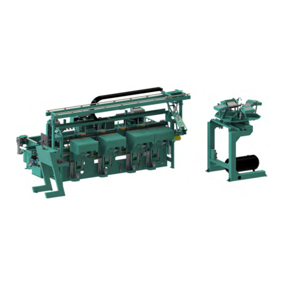
- Page 1 Service Manual Published: 5/24/2019 Innovation, Quality & Honesty 994-X Pre-Hanging Door System Includes Option RTS-FX...
- Page 2 Proprietary Notice This Manual is confidential and contains proprietary information and intellectual property of KVAL Inc., and is to be used solely by Customer as an operating manual for KVAL Inc. machines. Neither this Manual nor any of the information contained herein may be reproduced or disclosed under any circumstances without the express written permission of KVAL Inc.
- Page 3 KVAL 994-X Service Manual Your Feedback is Welcome: To help us design products that make your job easier and your business more successful, we'd like to gain your perspective about your user experience with our product - that is, the manual, the machinery, the software, etc.
- Page 4 KVAL 994-X Service Manual...
-
Page 5: Table Of Contents
Table of Contents Introduction to the 994-X System Chapter 1 Overview of the 994-X Door Hanging System ......1-2 Available Options..................1-3 About this Manual .................1-6 About this Manual .................1-6 Safety First!................1-7 Safety Sheet Sign-Off Sheet..............1-7 Safety Terminology of Labels..............1-7 Safety Guidelines..................1-7... - Page 6 Maintenance of the 994-X Chapter 3 Maintenance Schedule ............3-2 300 Cycle Maintenance Steps ..........3-4 Clean, Clean, Clean!................3-4 600 Cycle Maintenance Steps ..........3-5 Check Air Gauges and Inspect Water Traps ........3-5 Inspect Tooling..................3-5 Lubricate inside of Hopper..............3-6 Empty Dust Collection Units ..............3-6 3,000 Cycle Maintenance Steps ..........
- Page 7 About Taper Bearings .................3-20 Tapered Bearing Housings ..............3-20 Ball Screw Nut ..................3-21 Ball Screw Drive Assembly..............3-21 Pulley and Idler Shafts................3-22 Sample of Grease Locations for 994-X........3-23 Back Section Servo Motor Assembly..........3-23 Front Section Servo Assemblies............3-24 Cutting Head Base................3-25 Cutting Head Tools ................3-26 Grease Location on the Frame ............3-27...
- Page 8 Valve Bank Locations .............. 4-21 Location of Valve Banks ..............4-21 Using Sensors to Trouble Shoot ..........4-22 Location of Sensors on 994-X ..........4-23 Z Axis and Y Axis Front Section Sensors ...........4-24 X Axis Sensors Front Section .............4-25 Troubleshooting Electrical Problems ........4-26 If the Power Stops During Normal Operation........4-26...
- Page 9 CHAPTER 1 Introduction to the 994-X System This chapter provides an overview of the KVAL 994-X Door Hanging System and important safety information to follow when operating the machine. Chapter 1 at a Glance Section Name Summary Page This section provides an overview of the 994-X.
-
Page 10: Overview Of The 994-X Door Hanging System
1-1/2 hp Hi-Frequency spindle motor. The 994-X will accommodate doors with raised molding one or both sides up to 3/4" high, and a minimum of 4" between the raised molding and the edge of the door. -
Page 11: Available Options
Options RT-FX Single Head machine with the Rotary Hopper stand. The Rotary option allows kind change of screw type with preloaded screws. For detailed information about available options, please contact our KVAL Sales and Service department. Option Title Description Option A Six Shooter Gun for 3-1/2'' X To attach 3-1/2"... - Page 12 Light will be mounted on the out-feed end of the 990-F4 that can be seen by the 700-C Assembly Table operator. The light will be on when the door in the 994-X is being machined as a right hand door and off for a left hand door.
- Page 13 Title Description Option Servo Backsection with Cor- The 994-X system combines very high quality hardware ner Squaring detailing, with high speed productivity. Unique features include computer controlled ball screw movements for all router and chisels, complete with square lock face plates.
-
Page 14: About This Manual
Overview of the 994-X Door Hanging System About this Manual About this Manual This manual is part of a package delivered with the machine line. Integration Package includes the following: includes the following: Operation Manual Chapter Title Description Introduction Descriptions of Machine Line and Safety Information. -
Page 15: Safety First
See “Safety Sign-Off Sheet” on page 1-21. Safety Terminology of Labels In addition to the nameplate, KVAL machines may have other warning labels or decals that pro- vide safety information to operators. Safety labels should be clearly visible to the operator and must be replaced if missing, damaged, or illegible. - Page 16 Before performing any mainte- nance or repairs on this machine turn off the main air disconnect. Lockout and tagout this connection. See “Lockout Tagout Procedure” on page 1-12. KVAL 994-X Service Manual...
- Page 17 This should be done in accordance with applicable state and/or federal code requirements. Laser Warnings On some machines, laser indicators are used to set boundaries. Follow the manufacturers safety precautions. KVAL 994-X Service Manual...
- Page 18 Safety First! Compliance with Codes and Regulations KVAL advises that you request an on-site state safety review of your installation of this machine. This is to ensure conformance to any additional specific safety and health regula- tions which apply in your geographic area.
-
Page 19: Lockout-Tagout Guidelines
O..OFF! Shut off all power sources and isolating devices P..Place lock and tag E..ENERGY: Release stored energy to a zero-energy state R ..Recheck controls and test to ensure they are in the “OFF” state KVAL 994-X Service Manual 1-11... -
Page 20: Lockout Tagout Procedure
Turn Switch to the Lock and Tag out Insert Lock into hole. OFF position Note: When multiple people are working on the machine, each person needs to have a lock on the handle in the extra holes provided. KVAL 994-X Service Manual 1-12... -
Page 21: Lockout Tagout Air Supply
The lock and tag can now be removed (only by the person(s) who placed them), and the machine can be re-energized. The tags must be destroyed and the locks and keys returned to the lockout center. KVAL 994-X Service Manual 1-13... -
Page 22: Zero-Energy To Start-Up
Replace Guards Replace all equipment guards. If part of equipment cannot be properly adjusted after start-up with guard on, contact the KVAL Service team. See “Getting Help from KVAL” on page 1-16. Check Controls Confirm that all switches are in the “OFF”... - Page 23 Be sure to follow the P-R-O- P-E-R lockout/tagout procedures, and that those around you do also. Close the Cage Gate Verify all cage gates are securely closed. Ensure all safety protocols are in effect. KVAL 994-X Service Manual 1-15...
-
Page 24: Getting Help From Kval
• Outside the U.S. and Canada, call (707) 762-7367 or fax (707) 762-0485 • Email address is service@kvalinc.com • Hours: 6:00 AM to 4:00 PM Pacific Standard Time, Monday through Thursday 6:30 AM to 1:30 PM Pacific Standard Time, Friday KVAL 994-X Service Manual 1-16... -
Page 25: On-Line Help
Product Return Procedure If you’ve contacted Kval for help and it is determined that a return is necessary, use the procedure below to return the machine or part. Note: Non-Warranty returns are subject to a 15% restocking charge. -
Page 26: How To Download The Service Application
Download Application To download the application, go the KVAL website ( http:// www.kvalinc.com At the KVAL website, select the tab. Follow the instruc- Support tions on the Support web page. Click the Download button to download the application that... - Page 27 Session code: An internal number to track this machine. It is auto filled. Your Name Field: Enter your name. The KVAL tech- nician will use this field to identify this machine. Description: Enter machine Serial number and issue.
- Page 28 How to Download the Service Application Page Intentionally Left Blank KVAL 994-X Service Manual 1-20...
-
Page 29: Safety Sign-Off Sheet
Name (print):__________________Signature: __________________ Date:____/____/___ Note: It is recommended you make a copy of this sheet for new operators. If a copy is needed, you may download a PDF at the KVAL website (http:// www.kvalinc.com). You may also contact our Service Department at (800) 553-5825 or email at service@kvalinc.com. - Page 30 Safety Sign-Off Sheet KVAL 994-X Service Manual 1-22...
- Page 31 System IT Administration CHAPTER 2 This chapter describes the KVAL 994-X controller. The controller is an on board computer that supplies the user interface and controls the operation of the machine. With the controller, KVAL can remotely help troubleshoot your machine.
-
Page 32: About The 994-X Computer
Support will be able to access your machine through your company’s Intranet and help solve any issues that may occur. Connection to the Intranet is achieved by interfacing with the 994-X con- troller. The location of the Intranet connection is identified in the figure below (RJ45 to Intranet.) About the 994-X Computer ®... -
Page 33: Backing Up The Computer
About Remote Connection to KVAL Service Remote access is a powerful tool to help fix issues that occur with the 994-X machine. With the remote access, our KVAL service technician is able to observe your user screen in real time, read ®... - Page 34 System IT Administration KVAL 994-X Service Manual...
-
Page 35: Maintenance Of The 994-X
Maintenance of the 994-X CHAPTER 3 This chapter describes preventative maintenance steps for KVAL 994-X. The content is geared to guide technicians to keep a regular maintenance schedule for your KVAL machine. Keeping your KVAL machine maintained is an important piece for successful operation of your door production process. - Page 36 This should be done in accor- dance with applicable state and/or federal code requirements To view a video of the maintenance process, visit the KVAL website. Select the Video Tab to view videos. http://www.kvalinc.com/...
- Page 37 Inspect all nuts and bolts for tightnesses Tighten is necessary. Inspect Check that there is a smooth transition with a door feeding into and out of machine. Back-up Backup computer software. Clean Wash filter and lubricator bowls with soapy water. KVAL 994-X Service Manual...
-
Page 38: 300 Cycle Maintenance Steps
Check vertical bearings for loose screws. Loose screws could cause bearing damage. High Dust Accumulation Areas Lock Bore Area: build up can occur and stop Bolt drill from extending. Front Section: Underneath Car- riage Heads Jamb Clamp area. KVAL 994-X Service Manual... -
Page 39: 600 Cycle Maintenance Steps
Reverse action when installing trap. Inspect Tooling Inspect the Tooling for wear, (Drill Bits, Cutting Tools, Screw Driver Bits) See “Replacing Bits in the Front Section” on page 3-30 see “Replacing Tooling in the Back Section” on page 3-37. KVAL 994-X Service Manual... -
Page 40: Lubricate Inside Of Hopper
Check and empty any dust collection units. Clean any dust filters. Dust collection systems vary from machine to machine. Follow manufacturers directions to empty dust collection units. Filters Dust Collection Containers Typical Dust Collection Unit FIGURE 3-1. KVAL 994-X Service Manual... -
Page 41: 3,000 Cycle Maintenance Steps
• cracks • wear from rubbing • Ensure tube clamps are tight Inspect all Photo Eyes Inspect all photo eyes secure and tight. Check Nut that attaches Photo Eye to Machine Check Connection to Photo Eye KVAL 994-X Service Manual... -
Page 42: Inspect Limit Switches
5 or 20 degrees before the limit switch actuates. Inspect Screw Receiver Parts Inspect screw receiver parts on six shooters for cracks or breaks. Inspect: Screw Receiver Spring Split Shell Steel Ring Rubber Ring Steel Ring Replace any parts that are broken. KVAL 994-X Service Manual... -
Page 43: Inspect Airlines
Refill Lubricators Ensure Air is turned off. Refill all lubricators. Replace fluid if milky or discolored. Use ab ISO 32 stan- dard hydraulic oil (KVAL PN: SYS- LUBEG). Slide locking switch down twist bowl and remove. Refill bowl. Reverse action when installing trap. -
Page 44: Grease Ball Screw Bearings
Grease ball screw bearings (if applicable). For a table of lubrication types to use, Lubrication Schedule. For locations to lubricate, See Grease Ball Screw Bearings Clean Bearing Shafts Clean all bearing shafts with clean, dry cloth. Spray shaft with silicone oil and clean build up grime and dirt. KVAL 994-X Service Manual 3-10... -
Page 45: 12,000 Cycle Maintenance Steps
Cylinders not holding their position. Inspect Hydraulic Lines Inspect hydraulic lines for loose fittings, leaks and cracks. Inspect hydraulic lines from the source to the end assembly. KVAL 994-X Service Manual 3-11... -
Page 46: Inspect Ball Rail Shafts
Clean and lubricate all slides and cylinder rods with dry silicone spray. Clean inside Hopper Clean inside hopper with dry sili- ® cone oil and a 3M ScotchBrite pad (or equivalent). Wipe dry with a clean dry rag KVAL 994-X Service Manual 3-12... -
Page 47: 72,000 Cycle Maintenance Steps
Note: It is recommend to back-up to an outside source (server, isolated drive, etc) on a schedule of your choosing. The KVAL service team would be happy to help. If any questions occur, contact our service team at (800) 553-5825 or at www.kvalinc.com. -
Page 48: Wash Filter And Lubricator Bowls
Wash filter and lubricator bowls with soapy water. • Slide lock down to unlock. • Twist bowl to remove it. • Remove filter from Air filter assembly. Inspect and clean or replace if necessary. • Clean bowls and reas- semble. KVAL 994-X Service Manual 3-14... -
Page 49: Tool Changing Schedule
Changing and inspecting the tooling on a regular basis keeps the door machining process running accurately and efficiently. KVAL recommends using the tables below for reference to change or inspect the machine tooling. Note: Depending on Machine or Option, some of these tools may vary. -
Page 50: Maintenance No-Goes
• Do not adjust any and all flow controls from factory settings • Do not remove shim stock • Do not Change or Alter any safety assemblies (E-Stops, Gate Locks, etc) • Do not Change programs in PLC’s or PC’s • Do not Alter Electrical Components KVAL 994-X Service Manual 3-16... -
Page 51: Lubrication Schedule
Lubrication Schedule Lubrication Schedule KVAL recommends the following lubrication schedule to ensure that the machine operates prop- erly. Recommended Lubrication Schedule TABLE 3-1. Type of Recommended Schedule Recommended Assembly Lubrication Type Linear Bearing Pillow Block Bearing Every 250 Hours of Machine Operation... -
Page 52: Lubrication Requirements
Closed Pillow Block Hub Style Opened Pillow Block parallel perpendicular mount Greasing Approximatively 1 Gram (one pump from grease gun) of Dura-Lith Grease (KVAL P/N: Lube EP-2). Every 250 hours of operation. Pillow Block Bearings FIGURE 3-2. KVAL 994-X Service Manual 3-18... -
Page 53: Flange Bearing Housings
X,Y, or Z direction. Greasing Ball Rail Bearing Approximatively 1 Gram (one pump from grease gun) of Dura-Lith Grease (KVAL P/ Every 250 hours N: Lube EP-2). of operation. Ball Rail Bearings FIGURE 3-4. KVAL 994-X Service Manual 3-19... -
Page 54: About Taper Bearings
To identify a , look at the enclosure and verify there are seals Tapered Bearing Housing between the screw and the housing. Tapered Bear- ing Housing Tapered Bear- ing Seals Tapered Bearing Housing FIGURE 3-6. KVAL 994-X Service Manual 3-20... -
Page 55: Ball Screw Nut
Ball Screw Drive Assembly. Ball Screw Nut Recommended every 80 Hrs Servo Motor Pillow Block (Hub Style Recommended every 250 Hrs Tapered Bearing Housing Recommend One Pump 4 times a Year Ball Screw Drive Assembly FIGURE 3-8. KVAL 994-X Service Manual 3-21... -
Page 56: Pulley And Idler Shafts
Note: It is important not to overfill the Idler Shaft. Avoid getting excess grease on the belts Grease Out Approximatively 1 Gram (one pump from grease gun) of Dura-Lith Grease Idler Shaft (KVAL P/N: Lube Monthly EP-2). KVAL 994-X Service Manual 3-22... -
Page 57: Sample Of Grease Locations For 994-X
Sample of Grease Locations for 994-X Sample of Grease Locations for 994-X This machine is a powerful electro-mechanical Caution motion control system. If servicing this machine, fol- low the safety guidelines. Failure to do so can result in damage to equipment and/or serious injury to person- nel. -
Page 58: Front Section Servo Assemblies
Sample of Grease Locations for 994-X Front Section Servo Assemblies Identify zerk fittings and apply EP-2 grease. Find the X, Y and Z axis rails to identify bearings. Some bearings may be difficult to get access to. Use an extender to reach tight areas. Make sure to Lockout/Tagout before maintenance. -
Page 59: Cutting Head Base
Sample of Grease Locations for 994-X Grease Locations Cutter Head Identify zerk fittings and apply EP-2 grease. Find the X, Y and Z axis rails to identify bearings. Some bearings may be difficult to get access to. Use an extender to reach tight areas. Make sure to Lockout/Tagout before maintenance. -
Page 60: Cutting Head Tools
Sample of Grease Locations for 994-X Cutting Head Tools Below is a view of the with the ghosted. Cutter Head Tool Box Cutting Head Base Cutting Tools Z Axis: Each tool moves into the cutting surface independently. 1 rail 2 bearings per tool... -
Page 61: Grease Location On The Frame
Sample of Grease Locations for 994-X Grease Location on the Frame Use an extender to reach tight areas. Make sure to Lockout/Tagout before maintenance. For rec- ommended greasing schedule, see “Flange Bearing Housings” on page 3-19. and see “Pulley and Idler Shafts”... -
Page 62: Description Of Air Input System
Description of Air Input System Description of Air Input System There are two types of air inputs on KVAL machinery. Not all machines have lubricator option installed. Check your machine or Air prints to verify installation. Air Input with Lubrication The air input system takes in shop air and supplies clean dry air (CDA) and lubricated air to the machine. -
Page 63: Air Line Without Lubricator
The air input system takes in shop air and supplies clean dry air (CDA). Shop Clean Dry Air (CDA) t Air Blow Off Input Air On- Off Knob Muffler Filter (purge) Pressure Gauge with adjust Air Distribution Block Air Filter without Lubricator FIGURE 3-15. KVAL 994-X Service Manual 3-29... -
Page 64: Replacing Tooling In The Front Section
Option CH Pre Drill: Counter Rotate Router: Router: Standard Chisels: Two chisels per assembly. Square off Jamb and Door hinge cuts. Location of Bits in the 994-X Heads FIGURE 3-16. KVAL 994-X Service Manual 3-30... -
Page 65: How To Access To Bit Assemblies
Use a 17 mm shaft wrench and a 3/8 “collet wrench to remove the bit on the pre-drill or router assemblies. See Figure below. 3/ 8 “Collet Wrench (PN: PERER16W 17 mm Shaft Wrench (PN: WRENCH17MM) Removing Pre-Drill or Router Bit. FIGURE 3-17. KVAL 994-X Service Manual 3-31... - Page 66 Lightly tighten and torque to correct value. For torque values, See “Collet Torque Values” on page 3-40 Drill Depth Router Depth Set to 2.0” Set to 1 3/4 “ 1 3/4 ““ 2.0 “ Bit Depth Gauge (PN432C) Setting the Bit Depths FIGURE 3-19. KVAL 994-X Service Manual 3-32...
-
Page 67: Remove And Replace The Chisels
FIGURE 3-20. Slide in the new chisels. Tighten bolts back and forth until the bracket is tight. Inspect and verify the work. Clean the work area. If maintenance is completed, replace dust cover and tighten bolts. KVAL 994-X Service Manual 3-33... -
Page 68: Remove And Replace The Screwdriver Bits
Air Connector Receiver Disconnect air from Six-Shooter using the air-connect slide valves. Slowly slide the valves back toward you; listen for air to be released. Disconnect Air Connect to Bleed- Off Air Disconnect Air FIGURE 3-21. KVAL 994-X Service Manual 3-34... - Page 69 Remove and Replace the Screw Driver Bits To remove screwdriver bit, push the bit holder (see images) back toward the Six- Shooter assembly and hold: pull bit out of holder Location of Driver Bits Bit Holder Hinge Applicator Gear Box KVAL 994-X Service Manual 3-35...
- Page 70 Shooter assembly and hold while inserting new bit. Release holder to secure bit. Move Six-Shooter assembly back toward machine and pull the back slide toward you; then move assembly away from machine to restore assembly to original start- ing position KVAL 994-X Service Manual 3-36...
-
Page 71: Replacing Tooling In The Back Section
Lock Access Button Access Tools (OFF): Lock Plate for easy access. with , Moves the out further if more Lock Access Button Access Tools (ON: Lock Plate room is needed to access tooling. KVAL 994-X Service Manual 3-37... -
Page 72: Changing The Bore Drill
Note: The figure shows the cover off for training purposes. Changing the Bolt Drill Turn off all power to the machine. Follow proper lockout/tagout procedures Caution: as detailed in the safety section of Chapter 1 of this manual. KVAL 994-X Service Manual 3-38... - Page 73 3-40 Note: Make sure the arbor is not bottomed out in the back of the motor. If it is the arbor will not tighten and will damage the collet or other machine parts. KVAL 994-X Service Manual 3-39...
-
Page 74: Collet Torque Values
Collet Torque Values Collet Torque Values KVAL recommends torquing the collets. Torquing adds consistency is important for repeatable machining. Follow the torque tool manufacturers method of torquing. KVAL 994-X Service Manual 3-40... - Page 75 Collet Torque Values KVAL 994-X Service Manual 3-41...
- Page 76 Collet Torque Values KVAL 994-X Service Manual 3-42...
-
Page 77: Troubleshooting The 994-X
CHAPTER 4 This chapter describes troubleshooting steps to help technicians solve issues that may occur with your KVAL machine. If help is needed, call or contact our KVAL Service team at (800) 553-5825 or http://www.kvalinc.com. Refer to the Air and Electrical drawings provided with delivery of the machine. -
Page 78: About Motion Control
KVAL Machinery. Sequencing: Sequencing is a series of events executed in a predetermined order. Most KVAL machines use a form of sequential motion control. A typical series of events for a KVAL machine are: Move the door into position. - Page 79 • Moves the load. Examples: A motor or a pneumatic cylinder. The Position Feedback. • Provides location information to the controller. Examples: A limit switch, a photo eye, or ferrous eye, a resolver or an encoder KVAL 994-X Service Manual...
-
Page 80: Typical Positioning Systems
Should measure Relay Line Voltage here Power Input Control Contactor (Coil) Input 120 VAC Power Output Should measure DC - Control Circuit Line Voltage here Common Motor Block Diagram of a Common Contactor Circuit FIGURE 4-2. KVAL 994-X Service Manual... - Page 81 An adjustable-speed drive is used to control the motor speed and torque by varying motor input frequency and voltage. A variable-frequency drive (VFD) is used in KVAL machinery. The figure below shows a block diagram of a typical motor drive circuit with typical voltages.
- Page 82 Should have High Pressure air here Output Input Control Control (Coil) Valve Input Output Should have High Control Circuit Pressure air on Common Activated Output Cylinder Cylinder Extended Retracted Block Diagram of a Pneumatic Circuit FIGURE 4-4. KVAL 994-X Service Manual...
-
Page 83: Troubleshooting Basics
When was the last calibration? Is the door true? Use Router Bit Depth Gauge (PN: 432C) to check depth of Bits Check tools for wear. Check back side of “H” blocks for sawdust build-up, which may affect depth. KVAL 994-X Service Manual... -
Page 84: Analyze The Sub Systems
• Is the Load “bound up? • Is there sufficient lubrication? • Is it an alignment issue? • Is anything damaged? Check the Position Feed Back. • Does the Position Feed Back agree with the Load position? KVAL 994-X Service Manual... - Page 85 • Photo Eye: Bad element or bad cable • Limit Switch: Stuck, or failure • Wiring: Broken, worn insulation • PLC: Bad input port. Check the Positioning System Follow the circuit from the Controller output to the Load and check for component failures. KVAL 994-X Service Manual...
-
Page 86: About A Typical Contactor Control
Common DC - Thermal Control Coil for OverLoad 120 Vac. Should measure Line Voltage here Motor Schematic Drawing of Contactor and Thermal Overload Block Diagram of a Common Contactor Circuit FIGURE 4- 5. KVAL 994-X Service Manual 4-10... -
Page 87: About Contactor Troubleshooting
If the same overload keeps tripping, verify condition. Follow circuit path using the E-Drawing as a reference. a.Common issues: Check for bad wire, bad motor, or if load is too great for cur- rent draw. KVAL 994-X Service Manual 4-11... -
Page 88: About Typical Vfd Motor Drive Control
An adjustable-speed drive is used to control the motor speed and torque by varying motor input frequency and voltage. A variable-frequency drive (VFD) is used in KVAL machinery to accu- rately drive motors for machining or moving product through the machine. The figure below shows a block diagram of a typical motor drive circuit. -
Page 89: About The Vfd
Figure 4- 7 on page 4- VFD models vary in KVAL machines depending on where it is used, voltage requirements and type of PLC used. This is a general view on the VFD. See the machine’s Electrical Print for detailed information. -
Page 90: About Vfd Troubleshooting
Note: The number of reset buttons depends on the machine type and option. The fig- ure above shows a machine with 11 VFDs The VFD manuals are located in the Electrical Panels. On some machines, documentation can be found in the operation station in the documen- tation folder. KVAL 994-X Service Manual 4-14... -
Page 91: About A Typical Pneumatic Circuit
Note: In this sample set-up, Port A is nor- mally open and Port B is nor- mally closed. If power is OFF, air should be on Port B. Block Diagram of a Pneumatic Circuit FIGURE 4- 10. KVAL 994-X Service Manual 4-15... -
Page 92: Typical Pneumatic Assembly
About a Typical Pneumatic Circuit Typical Pneumatic Assembly Pneumatic assembly setups vary in KVAL machines depending on where it is used and air requirements.This is a general overview of a pneumatic assembly. See the machine’s Air Print for detailed information. -
Page 93: About Cylinder Operation
Router applies the control voltage to the which directs com- Control Valve pressed air to extend port of the Cylinder are extended deactivating the Cylinder Router Retract Sensor fully extends activating the Router Extend Sensor. KVAL 994-X Service Manual 4-17... - Page 94 Control Valve Cylinder. retract deactivating the Cylinder Router Extend Sensor When the are fully retracted, the is activated. Cylinder Router Retract Sensor senses the voltage from the completing the process Retract Sensor KVAL 994-X Service Manual 4-18...
-
Page 95: Important Notice About Adjusting Cylinder Speed
However, sometimes machine settling, mechanics be “broken in” may be cause to slightly adjust extend and retraction speed. If more than 1/2 turn on adjustment knobs are needed, call in a specialist or check with KVAL customer service at 1-800-553-5825. KVAL 994-X Service Manual 4-19... -
Page 96: Adjusting Cylinder Extend Speed
Adjusting Cylinder Extend Speed Adjusting Cylinder Retraction Speed Tip: If Installing a new flow control assembly, shut down the flow control and back out 4 to 5 turns. this position is a good starting point for kine adjust. KVAL 994-X Service Manual 4-20... -
Page 97: Valve Bank Locations
Location of Valve Banks Note: Refer to Machine Pneumatic Schematic for Defined Values Option: Back Section Valve Bank Narrow Valve Bank End Valve: Door Valve Bank Out-Feed Valve Banks: In-Feed Valve Banks Location of Valve Banks FIGURE 4-14. KVAL 994-X Service Manual 4-21... -
Page 98: Using Sensors To Trouble Shoot
• Check the output voltages of the sensors in inactive mode.The voltage should effec- tively equal 24 VDC The distance from an eye to the door should be in range. Typically the range should be 3/4'' to 7/8'' from the top of all eyes to the door. KVAL 994-X Service Manual 4-22... -
Page 99: Location Of Sensors On 994-X
Location of Sensors on 994-X Location of Sensors on 994-X Figure 4-15 below, shows the sensor locations on the 994-X The “I” designation represents an input to the PLC and the “Q” designation represents an output from the PLC. Door Sense Eye... -
Page 100: Z Axis And Y Axis Front Section Sensors
Z-Axis Home Eye Z-Axis Reverse Crash Eye Z-Axis Forward Crash Eye Y-Axis Home Eye Y-Axis Reverse Crash Eye Y-Axis Forward Crash Eye Section View of 994-X Y and Axis Sensors FIGURE 4-16. KVAL 994-X Service Manual 4-24... -
Page 101: Axis Sensors Front Section
The sensors are located underneath the Heads X-Axis Home Eye X-Axis Reverse Crash Eye X-Axis Forward Crash Eye Bottom View of 994-X location of X Axis Sensors FIGURE 4-17. KVAL 994-X Service Manual 4-25... -
Page 102: Troubleshooting Electrical Problems
Refer to Air and Electrical Schematics provided with delivery of the machine. Schematics are located in the Electrical Panel. If copies NOTE: are unavailable, contact the KVAL Service Department. Have model number and serial number of machine readily available. Warning The following checks require the electrical panel to be energized. -
Page 103: Troubleshooting With The Status Light Panel
The Status Light Panel is located on the Electrical Panel. All six lights are illuminated when the system is in proper working order. The lights turn on in a sequence and will stop at the point where a fault is first detected. KVAL 994-X Service Manual 4-27... - Page 104 STEP 4: Stop (Amber) If light is OFF go to item D on page 4-30. STEP 5: Start (Amber) If light is OFF go to item E on page 4-31. STEP 6: 24VDC (Green light is OFF go to item F on page 4-31. KVAL 994-X Service Manual 4-28...
- Page 105 If no power on the output side, and there is power going into the top of the Control Transformer, replace the Control Transformer. If there is power at the Control Transformer, check the wiring of the black and white wire going from the Control Transformer to the 110 VAC Terminal Strip. KVAL 994-X Service Manual 4-29...
- Page 106 Start button. If no voltage, check the Stop button to make sure it is all the way out and not stuck in, then check the contact to make sure it is closed. If still no voltage, check the wiring. KVAL 994-X Service Manual 4-30...
- Page 107 Check for +24VDC at between any –DC and +DC terminal on the DC Terminal block. Reinstall the (+ 24V positive) wires one by one, checking for +24VDC after installing each. If at any point no voltage is found trace the last reinstalled wire and check for shorts. KVAL 994-X Service Manual 4-31...
-
Page 108: Network System Overview
Network System Overview Network System Overview A PLC controls the 994-X. The 994-X PLC can process multiple analog and digital inputs, and output arrangements. The system can handle extended temperature ranges, immunity to electrical noise, and resistance to vibration and impact. -
Page 109: Connections To Servo Drives
2 High Voltage Servo Drive 3 2 High Voltage 2 High Voltage Outputs Servo Drive 2 Servo Drive 5 2 High Voltage Servo Drive 4 2 High Voltage Outputs 2 High Voltage Outputs Servo Drives FIGURE 4-19. KVAL 994-X Service Manual 4-33... -
Page 110: Connections To Vfd's (High Freq Panel)
Network System Overview Connections to VFD’s (High Freq Panel) The VFD servos are located in the High Freq Electrical Panel. For detailed wiring information, see your machine’s electrical drawings. VFD’s are located in the High Frequency Panel. KVAL 994-X Service Manual 4-34... -
Page 111: Symptoms And Possible Causes
Slide valve on screw drop cylin- Push Slide Valve On lic Screw Head will der turned off. Un-jam Screw Slide not Start Jammed Screw Re-adjust Limit Switch Arms Limit Switch Out of Adjustment Replace Fuses Bad Fuse KVAL 994-X Service Manual 4-35... - Page 112 Empty Hopper Put Screws in the Hopper Jammed Split Shells Disassemble the Screw Receiver Routers Not Moving Through Beams Not Lined Up Pick Up on the Last Router Car- Into Home Position riage to realign. KVAL 994-X Service Manual 4-36...
- Page 113 3-17 1-18 return material authorization (RMA) 1-16 returning the product to Kval 1-16 Idler Shaft 3-17 internet access KVAL 994-X Service Manual...
- Page 114 3-34 sensors location on frame 4-23 troubleshooing 4-22 x-axis and y-axis locations 4-24 service connecting your machine to KVAL Service service center, contacting information 1-16 servo drives connections location 4-33 start light description 4-31 status light panel...
- Page 116 Contacting KVAL Customer Service Phone and Fax: Mailing address: In the U.S and Canada, call (800) 553-5825 or fax Customer Support Department (707) 762-0485 Kval Incorporated Outside the U.S. and Canada, call (707) 762-7367 825 Petaluma Boulevard South or fax (707) 762-0485 Petaluma, CA 94952 Email: service@kvalinc.com...
Need help?
Do you have a question about the 994-X and is the answer not in the manual?
Questions and answers