Kval 990-FX Operation Manual
Pre-hanging door system
Hide thumbs
Also See for 990-FX:
- Operation and service manual (172 pages) ,
- Service manual (120 pages) ,
- Operation manual (104 pages)

Related Manuals for Kval 990-FX


Summary of Contents for Kval 990-FX
- Page 1 Operation Manual Published: September 28, 2021 Innovation, Quality & Honesty 990-FX Pre-Hanging Door System Includes Machines with Array Hoppers and Machines with RTS-FX Hoppers...
- Page 2 Proprietary Notice This Manual is confidential and contains proprietary information and intellectual property of KVAL Inc., and is to be used solely by Customer as an operating manual for KVAL Inc. machines. Neither this Manual nor any of the information contained herein may be reproduced or disclosed under any circumstances without the express written permission of KVAL Inc.
- Page 3 KVAL 990-FX Operation Manual Your Feedback is Welcome: To help us design products that make your job easier and your business more successful, we'd like to gain your perspective about your user experience with our product - that is, the manual, the machinery, the software, etc.
- Page 4 KVAL 990-FX Operation Manual...
-
Page 5: Table Of Contents
Safety Sign-Off Sheet .............. 1-21 A Note to the Operator................1-21 Operation of the 990-FX Chapter 2 Initial Powering Operations for the 990-FX Line ...... 2-2 How to Power Up the Line ..............2-2 Home the 990-FX .................2-3 How to Power Down the Machine............2-4... - Page 6 Axis Direction..................2-26 Diagnostic Screen..............2-27 Tour of the 990-FX Chapter 3 Machine Component Terms ............. 3-2 Common 990-FX Line Layout..........3-3 Assembly Identification on Machine ........3-4 Machine with an Array Hopper..............3-4 Machine with RTS-FX................3-5 About the RTS-FX ..............3-6 Summary of the Controls on the Machine Line......
- Page 7 About the Light Curtain ...............3-11 If the Beam is Broken .................3-11 To Resume Normal Operation after an Beam is Broken.....3-12 Air Brake on 990-FX Six Shooter............3-13 Tour of the Machine ..............3-14 About the In-Feed Section ..............3-14 About the Front Section ..............3-15 Machine with 8 Foot Door Option ............3-16...
- Page 8 Table of Contents 990-FX Operation Manual...
-
Page 9: Chapter 1 At A Glance
Chapter 1 at a Glance Introduction to the 990-FX CHAPTER 1 This chapter provides an overview of the Door Hanging System and important KVAL 990-FX safety information to follow when operating the machine. Chapter 1 at a Glance Section Name... -
Page 10: Overview Of The 990-Fx Door Hanging System
Overview of the 990-FX Door Hanging System Overview of the 990-FX Door Hanging System is the fastest and most productive pre-hanging system available in the industry. KVAL's 990-FX will rout a door and jamb for three or four hinges, drill pilot holes for the hinge 990-FX screws, mortise for the lock, and apply three or (Opt four) hinges. -
Page 11: Table Of Available Options
Light will be mounted on the out-feed end of the 990-FX that can be seen by the 700-C Assembly Table operator. The light will be on when the door in the 990-FX is being machined as a right hand door and off for a left hand door. -
Page 12: About This Manual
Overview of the 990-FX Door Hanging System About this Manual This manual is part of a package delivered with the machine line. Integration Package includes the following manuals: Operation Manual Chapter Title Description Introduction Descriptions of Machine Line and Safety Information. -
Page 13: Safety First
Training Ensure that all employees who operate this machine are aware of and adhere to all safety precautions posted on the machine and are trained to operate this machine in a safe manner. KVAL 990-FX Operation Manual... - Page 14 Before performing any mainte- nance or repairs on this machine turn off the main air disconnect. Lockout and tagout this connection. See “Lockout Tagout Procedure” on page 1-10. KVAL 990-FX Operation Manual...
- Page 15 This should be done in accordance with applicable state and/or federal code requirements. Laser Warnings On some machines, laser indicators are used to set boundaries. Follow the manufacturers safety precautions. KVAL 990-FX Operation Manual...
- Page 16 Follow Your Company’s Safety Procedures In addition to these safety guidelines. Your company should have on-site and machine specific safety proce- dures to follow. KVAL 990-FX Operation Manual...
-
Page 17: Lockout-Tagout Guidelines
O..OFF! Shut off all power sources and isolating devices P..Place lock and tag E..ENERGY: Release stored energy to a zero-energy state R ..Recheck controls and test to ensure they are in the “OFF” state KVAL 990-FX Operation Manual... -
Page 18: Lockout Tagout Procedure
Turn Switch to the Lock and Tag out Insert Lock into hole. OFF position Note: When multiple people are working on the machine, each person needs to have a lock on the handle in the extra holes provided. KVAL 990-FX Operation Manual 1-10... -
Page 19: Lockout Tagout Air Supply
The lock and tag can now be removed (only by the person(s) who placed them), and the machine can be re-energized. The tags must be destroyed and the locks and keys returned to the lockout center. KVAL 990-FX Operation Manual 1-11... -
Page 20: Zero-Energy To Start-Up
The Company’s procedures should also include provisions for safely handling shift changes and changes in operators or new operators.Comprehensive lockout/tagout may use a gang box or other system to ensure that locks are secure and not removed without authorization. KVAL 990-FX Operation Manual 1-12... - Page 21 Be sure to follow the P-R-O- P-E-R lockout/tagout procedures, and that those around you do also. Close the Cage Gate Verify all cage gates are securely closed. Ensure all safety protocols are in effect. KVAL 990-FX Operation Manual 1-13...
-
Page 22: Getting Help From Kval
6:30 AM to 1:30 PM Pacific Standard Time, Friday • What is the extent of the failure/reason for return? What are the relevant error mes- sages or error codes? • How long did it operate? KVAL 990-FX Operation Manual 1-14... - Page 23 • Make sure the item(s) you are returning are securely packaged and well protected from shipping damage • Include the packing slip or invoice numbers. • Include the documented reason for return. • Include the RMA number with the parts package. KVAL 990-FX Operation Manual 1-15...
-
Page 24: Kval Return And Warranty Policy
We can only accept items for a return if they are still in their original packaging and in undam- aged, resalable condition. Returns are accepted within 45 days of purchase and with an RMA number issued by Kval Inc. Returns after 45 days of purchase or without a Kval Inc. issued RMA number will not be accepted. -
Page 25: Customer Errors
Kval provides a warranty to products that are deemed defective. Within 30 days of discovery of said defect, please notify Kval, but no more than one (1) year after delivery will the product be covered under Warranty. The repair, replacement, or payment in the manner described above shall be the exclusive remedy of Buyer for breach of Kval’s warranty or for claims based upon failure... -
Page 26: How To Download The Service Application
Follow the instruc- Support tions on the Support web page. Click the Download button to download the application that allows the KVAL technician to have access to the operator sta- tion. After the download is com- pleted, double-click the program icon. - Page 27 Session code: An internal number to track this machine. It is auto filled. Your Name Field: Enter your name. The KVAL tech- nician will use this field to identify this machine. Description: Enter machine Serial number and issue.
- Page 28 How to Download the Service Application Page Intentionally Left Blank KVAL 990-FX Operation Manual 1-20...
-
Page 29: Safety Sign-Off Sheet
Note: It is recommended you make a copy of this sheet for new operators. If a copy is needed, you may download a PDF at the website (http://www.kvalinc.com). KVAL You may also contact our Service Department at (800) 553-5825 or email at ser- vice@kvalinc.com. KVAL 990-FX Operation Manual 1-21... - Page 30 Safety Sign-Off Sheet KVAL 990-FX Operation Manual 1-22...
- Page 31 Operation of the 990-FX CHAPTER 2 This chapter describes the power-up and user interface of the KVAL 990-FX Door Hanging System. The content is geared to help operators understand the basic operation of the 990-FX. Chapter 2 at a Glance...
-
Page 32: Initial Powering Operations For The 990-Fx Line
Initial Powering Operations for the 990-FX Line Initial Powering Operations for the 990-FX Line This section describes how to power up and to power down the Line. 990-FX Powering up the system includes: • Applying power to the entire system •... -
Page 33: Home The 990-Fx
Initial Powering Operations for the 990-FX Line Initiate the to act as a Reset. Hinge Loaded Note: This process is a safety precaution to ensure the no personnel is in the machine staging area. Push the Hinge Loaded Button All lights on the status light panels on the electrical box should be illuminated. -
Page 34: How To Power Down The Machine
Initial Powering Operations for the 990-FX Line How to Power Down the Machine Push the button for each machine, located on the Stop Operator’s Station Shut down the operating system, by selecting Shutdown from the Desktop. Note: Make sure Windows is shutdown completely before turning off the machine. -
Page 35: Machine Start Summary
Double Click the desktop icon. Press the button to start the process. Hinge Loaded Select the After all Home Machine Line Button. machine is , the machine status will display Homed Idle in the Machine Feedback Status box. KVAL 990-FX Operation Manual... - Page 36 Load Jamb on top of ledge pressing Hand Place- tightly against fence. ment and Warning Stickers on the Machine. After Jamb is secure, press the Jamb Clamp to clamp the Jamb Foot Pedal KVAL 990-FX Operation Manual...
- Page 37 Move out of area beyond Light Curtain When outside of Light Curtain, press the button to Hinge Loaded start the process. Repeat from Step (Load Jamb) until completed. Take Note of the Status Blink codes. KVAL 990-FX Operation Manual...
-
Page 38: Description Of User Interface Screens
Setup Screen: Calibrate the position of the machine operations. Error messages can be lock location. seen here for troubleshooting. See “About the Setup Screen” on page 2-21. See “Diagnostic Screen” on page 2-27. 990-FX Menu Map FIGURE 2-1. KVAL 990-FX Operation Manual... -
Page 39: Machine Feed Back
The information generated is as follows:’ General Machine Status Front Section Status Back Section Status Current Servo Positions Note: Use this information to isolate issues if having problems with the machine. KVAL 990-FX Operation Manual... -
Page 40: About The Main Screen
Note: Screen layouts may differ due to options that were ordered with the machine. Main Screen: 4 Carriage Head with Array Hopper Main Screen FIGURE2- 2. Note: Call-outs “A and B” are commonly used buttons and appear on all the screens. KVAL 990-FX Operation Manual 2-10... -
Page 41: Main Screen: 3 Carriage Head With Rts-Fx
Main Screen: 3 Carriage Head with RTS-FX The controls are the same as a machine with an Array Hopper or integrated Hoppers with the exception of three Hopper buttons to represent each Hopper set on the RTS-FX KVAL 990-FX Operation Manual 2-11... -
Page 42: Machine Controls
Shut Down Button This button shuts down the computer. Use this button as part of the shutdown pro- cess.See “Initial Powering Operations for the 990-FX Line” on page 2-2 Exit Application Button This button shuts down Interface Program and defaults to the Windows Desktop... - Page 43 Displays the length of the door in process. Door Length: This value is originated from the Preset or may be manu- ally selected. • Displays the “Hand Orientation” of the Door Handling: door in process. Originated form the machine selection. KVAL 990-FX Operation Manual 2-13...
- Page 44 Three Head Machines • Heads 1 and 3 can be disabled as a pair. • Head 2 can be disabled by itself. Review Calibration aspects of the Hinge groups, Note: “Screw Shift” on page 2-25 KVAL 990-FX Operation Manual 2-14...
- Page 45 Note: Load Manual button on the . In most cases Air Injection Main Screen these controls at located on the manual screen. For defi- nitions, see “Screw Delivery Manual Control” on page 2- KVAL 990-FX Operation Manual 2-15...
-
Page 46: Lock Group
Face Plate. Face Plate: Face Plate • indicates the backset distance for the each downloaded preset. Lock Backset: • Press to Enable or Disable the Ball Catch. Ball Catch (Option): KVAL 990-FX Operation Manual 2-16... -
Page 47: About Manual Operation
At this screen, control certain functions of the machine in manual mode. This screen is mainly used in troubleshooting, checking cut specifications, and maintenance. Note: Screen layouts may differ due to options that were ordered with the machine. Manual Operation Screen FIGURE 2-3. KVAL 990-FX Operation Manual 2-17... -
Page 48: Width Adjust
To return to previous speed, release the button. Speed Clamp and Stop: • Press the button to extend or retract the appropriate door stop. Stop: Stop • : Press to activate the cylinders that clamp the door. Clamp Clamp KVAL 990-FX Operation Manual 2-18... -
Page 49: Lock Manual Control
Use this button if a new Chipout Blocks are installed on the Hinge Carriage section. Press the to start the burn sequence. a new hole will be slowly drilled. the process will automati- cally stop when finished. KVAL 990-FX Operation Manual 2-19... - Page 50 Test Mode runs the hinge cycle, but does not extend the tools. This is primarily used to verify a new template is correct and the hinge carriage will not bump into the H- Block or other assemblies. KVAL 990-FX Operation Manual 2-20...
-
Page 51: About The Setup Screen
Note: Screen layouts may differ due to options that were ordered with the machine. Machine with RTS-FX Machines with a Hopper includes a separate calibration page. Select the RTS-FX RTS Hopper to jump to the calibration screen. See “About the RTS Hopper Setup” on page 2-26. Setup button KVAL 990-FX Operation Manual 2-21... -
Page 52: Enter A Positive Or Negative Number
Note: Maximum offset is 0.50 inches. If more than 0.50 inches of adjustment is needed, there is a high probability that another issue may be causing a problem. If issues can not be resolved, contact the See “Getting Help from KVAL” on KVAL Service Center KVAL Inc. (1-800-553-5825). -
Page 53: Calibration Steps For The Lock Location
If the lock location is correct, there is no need to perform this process, If it is not correct, follow the instructions in see “Adjusting Lock Location” on page 2-24 Reference Door Lock FIGURE2- 4. KVAL 990-FX Operation Manual 2-23... -
Page 54: Adjusting Lock Location
Either process is finishing too soon or later than each other, use the this routine. Note: This is rarely used. In some cases severe climate changes may cause some of the cylinders to become sluggish. KVAL 990-FX Operation Manual 2-24... - Page 55 Example of a 4 Head Machine Head #1 and #2 Head #3 and #4 3 Head Machine Back Section KVAL 990-FX Operation Manual 2-25...
-
Page 56: About The Rts Hopper Setup
Hopper Sets #1 through # 3: Calibrate each Hopper set individually. Axis Direction • A positive number moves the Hopper in the Clockwise direction. • For more information about using the calibra- tion boxes, see “Entering Calibration Offsets” on page 2-22 KVAL 990-FX Operation Manual 2-26... -
Page 57: Diagnostic Screen
The top line will have the most current routine that is running. If the machine issue can not be resolved, call KVAL Inc. (1-800-553-5825). Have any error code that is displayed, ready to give the KVAL representative. - Page 58 Total: Number of doors pro- Daily count of doors. cessed from the Initial start up of the machine. Cannot be Reset. Daily: Number of doors pro- cessed through-out the day. This is additive until reset. KVAL 990-FX Operation Manual 2-28...
- Page 59 Tour of the 990-FX CHAPTER 3 This chapter describes components, assemblies, of the KVAL 990-FX Door Hanging System. content is geared to help operators understand the basic operation of the 990-FX. Chapter 3 at a Glance Section Name Summary Page...
-
Page 60: Machine Component Terms
The Six-Shooter is located at the left side of the machine.Six Shooters apply hinges and the secures them with screws. (3x3 pattern) Eight-Shooter The Eight -Shooter is located at the left side of the machine.Eight Shooters apply hinges and the secures them with screws. (4X4pattern) (Opt K) KVAL 990-FX Operation Manual... -
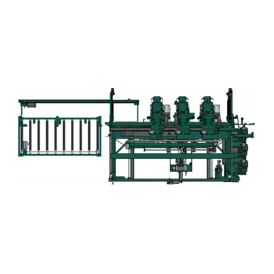
Page 61: Common 990-Fx Line Layout
• The door is placed onto the powered roller • )The door is fed into the 990-FX automatically or with a call door function. • After the door is fed into the 990-FX the action is repeated • For a detailed description of the Feeder, see... -
Page 62: Assembly Identification On Machine
Back Section Six Shooter 3 Lock Bore Assembly Carriage Head 3 Carriage Head 2 Air Tank Front Section Six Shooter 2 Carriage Head 1 Six Shooter 1 Light Curtain Transmitter Electrical Panel # 1 In-Feed Operator’s Station KVAL 990-FX Operation Manual... -
Page 63: Machine With Rts-Fx
Six Shooter 2 Lock Bore Assembly Carriage Head 3 Six Shooter 3 Electrical Panel # 1 Front Section Light Curtain Transmitter Out-Feed Hopper A RTS-FX Hopper B Hopper C To Six Shooters To Six Shooters To Six Shooters KVAL 990-FX Operation Manual... -
Page 64: About The Rts-Fx
• Screws can be easily reloaded into the hoppers when rotated in alignment with the hinge side of the 990FX. Rotary Hopper FIGURE 3-6. KVAL 990-FX Operation Manual... -
Page 65: Summary Of The Controls On The Machine Line
This section describes the controls located on the machine line. About the Operator Station Touch Screen Interface: Main Control of the 990-FX. Auto load and run predetermined parameters on doors. Manually control the door path and process through the line. Machine... -
Page 66: Descriptions Of Machine Controls
No changes to the parameters may be made in the off position. The key may be taken out in the off position, to prevent any inadvertent changes to the cut parameters. Set Up Lock KVAL 990-FX Operation Manual... -
Page 67: Foot Pedal And Control Box
The Six-Shooter heads will also begin to move into position. Door Auto RH / LH: Press for Auto Run, or to receive either a left-hand or right-hand incoming door. When in “Auto Door” mode, the 990-FX receives information about the incoming door from the incoming machine. -
Page 68: Hinges Loaded Button (Light Curtain Status Light)
The Hinge Loaded button is located on the frame. Light Curtain Hinges Loaded: Step out of the Safety Light Curtain and press this button after hinges are loaded on to the Hinge Applicators.The Light Curtain will be activated. KVAL 990-FX Operation Manual 3-10... -
Page 69: Safety Controls
If the beam is broken, the machine will shut down. This is safety feature performs the same func- tion as an Emergency Shutdown (E- Stop). For information on the E-Stop function, see “Emer- gency Shutdown and Recovery” on page 3-11 KVAL 990-FX Operation Manual 3-11... -
Page 70: To Resume Normal Operation After An Beam Is Broken
To Resume Normal Operation after an Beam is Broken If a Beam is broken, use the following procedure to recover. Push the button on START MACHINE the operator's station Press the Hinge Loaded Button. the Machine 3. Home KVAL 990-FX Operation Manual 3-12... -
Page 71: Air Brake On 990-Fx Six Shooter
Safety Controls Air Brake on 990-FX Six Shooter Air brakes are attached to the Six Shooter assemblies. The brakes will lock the six shooter in place avoiding a crash to the head. The brakes are controlled by a lack of air pressure and will lock when the air pressure drops below a reference level. -
Page 72: Tour Of The Machine
Six Shooter from Hopper In-Feed System Lock Back Section Door is delivered from previous machine and fed Faceplate routing into 990-FX for process- and boring for lock ing. and bolt In Pocket Sensor: A through beam that Frame Node... -
Page 73: About The Front Section
Head #3 Head #4 The RTS-FX Hopper sets are labeled A-C. Each hopper in the set delivers to Six Shooters 1 through 3. Refer to the RTS-FX to confirm lettering and numbering. Front Section FIGURE 3-10. KVAL 990-FX Operation Manual 3-15... -
Page 74: Machine With 8 Foot Door Option
Six Shooters Car- are used to process the door. riage Heads #2 - #4 When processing 8’-0” doors all Carriage Heads are used to process a door and Six Shooters KVAL 990-FX Operation Manual 3-16... -
Page 75: About The Hinge Carriage
Air Driven. Router: Routs the hinge pocket on the Pre-Drill jamb and the door at the same time as the counter rotate router. Router Jamb Predrill Bits Door Predrill Bits KVAL 990-FX Operation Manual 3-17... -
Page 76: About The Six Shooter System
Important: Do not adjust any of the Hopper air cylinders. They are adjusted at the factory. Any adjustment may cause timing issues with the operation of the Six Shooter. If you think problems are being caused by the cylinders, please contact the KVAL Service Department for direction. KVAL 990-FX Operation Manual 3-18... -
Page 77: Hopper Process
Once the Hopper is in the up position, the door will open and the Hopper will cycle down quickly to throw the surplus of screws out the funnel container. KVAL 990-FX Operation Manual 3-19... -
Page 78: About The Six Shooter Assembly
Allows the Six Shooter to the move to the side for Maintenance and Manual application of Hinges Vertical Cylinder: Drives Six Shooter Up and Down Driver Assembly: Vertical Rails: Hinge Application: Six Shooter Call-Outs Hoppers on machine FIGURE 3-12. KVAL 990-FX Operation Manual 3-20... -
Page 79: Six Shooter (Hopper Array On Floor)
Maintenance and Manual application of Hinges Vertical Cylinder: Drives Six Shooter Up and Down Driver Assembly Vertical Rails: Hinge Application: Six Shooter Call-Outs Hoppers Separate Array on Floor FIGURE 3-13. KVAL 990-FX Operation Manual 3-21... -
Page 80: Driver Assembly
Factory set to align hinge. Latch Arm: Latch Arm Cylinder: Latches to H Block Moves latch arm in and out to secure in place. of position Six Shooter and Gear Box Call-Outs FIGURE 3-14. KVAL 990-FX Operation Manual 3-22... -
Page 81: About The Back Section
Machines Hole for Bolt Chip Out Location: Lock Bore Lock Bore Motor and Drill: Drills locks holes on the face of the door Key Assemblies on the Back Section (View from Front Section) FIGURE 3-15. KVAL 990-FX Operation Manual 3-23... -
Page 82: Back View Of Rear Section
Clamps edge of door Edge Clamp: Clamps edge of door Oil Reservoir Lock Bore Extend and Retract Cylinder Deep Lock Bore Limit Shallow Switches Retracted Key Assemblies on the Back Section (Back View) FIGURE 3-16. KVAL 990-FX Operation Manual 3-24... -
Page 83: About The Out-Feed
Hydraulic Tanks for Six Shooters to the next machine. Sen- sors detect position of Supplies hydraulic pressure to operate Six Shooter. door and when to send it out. Key Assemblies on the Out-Feed Section FIGURE 3-17. KVAL 990-FX Operation Manual 3-25... -
Page 84: About The Electrical Panels
PLC with Inputs /Outputs High Voltage Section Ethernet Dist. Block • Disconnect • PDR • Fuses Servo Drive Control Transformer • Lock Carriage • Option: Infeed Shift • Option Outfeed Shift Main Electrical Box Overview FIGURE3- 18. KVAL 990-FX Operation Manual 3-26... -
Page 85: High Frequency Panels
• Fuses • Hinge Routere(1-4) • Face Plate Router • Feed Motor • Width Adjust Contactors and Thermal Over load Circuits • Lock Bore • Screw Drivers(1-4) • Bolt Drill Overview High Frequency Panel FIGURE 3-19. KVAL 990-FX Operation Manual 3-27... -
Page 86: About The Nodes
For example, door sensors, width adjusts, and tool interfaces. PLC Interface Inputs and Outputs Top Ethernet cable is from PLC Bottom Ethernet goes to Cutter Node Interconnect Bar Sample of a Frame Node FIGURE 3-20. KVAL 990-FX Operation Manual 3-28... -
Page 87: Example Of Node Connections
Inputs/Outputs originate at this box and are connected to Nodes. Back Section Node Power Distributed to Points in the machine Screw Driver 2 Screw Driver 1 Network Connections Frame Node Location of Nodes on Machine FIGURE3- 21. KVAL 990-FX Operation Manual 3-29... -
Page 88: Options
Options Options This section describes some of the common options offered by KVAL. Your machine may not have these options. Option BC: Ball Catch Drill assemblies are mounted onto the lock boring section for drilling left hand and right hand doors for drive-in ball catches. -
Page 89: Option: 8-0 Foot Door For Fx
1,2,3,and 4 into working posi- tion Shift Out The Shift Out Function moves Car- riages 1,2,3,and 4 into a position to allow the operator into the machine processing area. Allows the operator to insert the jamb into the machine. KVAL 990-FX Operation Manual 3-31... -
Page 90: Option H: Securing Split Jambs
During process, The split jamb auto triggers the firing mechanism of the staple gun. Note: The nail gun will not fire unless the enable button is activated on the Operators Screen and the safety switches are activated by the male split jamb. KVAL 990-FX Operation Manual 3-32... -
Page 91: Option Z: Screw Changing Hoppers
Screw-changing hoppers for changing screw colors. Enables the operator to change or add screws at floor height. Set up containers to catch the screws Select the Manual Screen Tab Press the Quick Dump Hopper Button. Pour new screw style into each hopper. Continue processing doors. Dump Area KVAL 990-FX Operation Manual 3-33... -
Page 92: Description Of The Six Light Panel
Description of the Six Light Panel The six lights on this panel indicate the status of the Commander III system. The Sequence that the lights activate is as follows: Control Power Overload Relay E-Stop Stop Start 24VDC KVAL 990-FX Operation Manual 3-34... - Page 93 3-26 out-feed emergency shutdown key assemblies 3-25 description 2-4, 3-11 front section location in main electrical panel 3-26 key assemblies 3-17 power front section status lock out procedure 1-10 feedback 2-9 preset selection description 2-14 Kval 990-FX...
- Page 94 2-12 six light panel description 3-34 sequence list 3-34 start machine button power up 2-2 stop sequence button description user interface 2-12 tagout procedure 1-10 user interface screens menu map 2-8 zero-energy start-up clean up 1-12 inspect 1-12 Kval 990-FX...
- Page 96 Customer Service Contacting KVAL Phone and Fax: Mailing address: In the U.S and Canada, call (800) 553-5825 or fax Customer Support Department (707) 762-0485 Kval Incorporated Outside the U.S. and Canada, call (707) 762-7367 825 Petaluma Boulevard South or fax (707) 762-0485 Petaluma, CA 94952 Email: service@kvalinc.com...
Need help?
Do you have a question about the 990-FX and is the answer not in the manual?
Questions and answers