Kval 990-FX Operation Manual
Pre-hanging door system
Hide thumbs
Also See for 990-FX:
- Operation and service manual (172 pages) ,
- Service manual (120 pages) ,
- Operation manual (104 pages)

Related Manuals for Kval 990-FX


Summary of Contents for Kval 990-FX
- Page 1 Operation Manual Published: May 21, 2019 Innovation, Quality & Honesty 990-FX Pre-Hanging Door System...
- Page 2 This Manual is confidential and contains proprietary information and intellectual property of KVAL Inc., and i s to be used solely by Customer as an operating manual for KVAL Inc. machines. Neither this Manual nor any of the information contained herein may be reproduced or disclosed under any circumstances without the express written permission of KVAL Inc.
- Page 3 KVAL 990-FX Operation/Service Manual Your Feedback is Welcome: To help us design products that make your job easier and your business more successful, we'd like to gain your perspective about your user experience with our product - that is, the manual, the machinery, the software, etc.
- Page 4 KVAL 990-FX Operation Manual...
-
Page 5: Table Of Contents
Table of Contents Introduction to the 990-FX Door Hanging System Chapter 1 Chapter 1 at a Glance.............. 1-1 Overview of the 990-FX Door Hanging System....... 1-2 Table of Available Options ..............1-2 About this Manual .................1-4 Safety First!................1-5 Safety Sheet Sign-Off Sheet..............1-5 Safety Terminology of Labels..............1-5... - Page 6 About the Electrical Panels..............2-23 Description of the Six Light Panel ........... 2-25 Machine Start Summary ............2-26 Initial Powering Operations for the 990-FX Line ...... 2-29 How to Power Up the Line ..............2-29 Home the 990-FX ................2-30 How to Power Down the Machine............2-31 Emergency Shutdown and Recovery ..........2-31...
- Page 7 Table of Contents Entering Calibration Offsets..............2-44 Calibration Steps for the Lock Location ..........2-45 Lock Location Calibration ..............2-45 Diagnostic Screen..............2-49 Door Count ..................2-50 Appendix: Machine Component Terms........2-51 KVAL 990-FX Operation Manual...
- Page 8 Table of Contents KVAL 990-FX Operation Manual...
-
Page 9: Chapter 1 At A Glance
Chapter 1 at a Glance Introduction to the 990-FX Door Hanging CHAPTER 1 System This chapter provides an overview of the KVAL 990-FX Door Hanging System and important safety information to follow when operating the machine. Chapter 1 at a Glance Section Name... -
Page 10: Overview Of The 990-Fx Door Hanging System
KVAL's 990-FX is the fastest and most productive pre-hanging system available in the industry. The 990-FX will rout a door and jamb for three or four hinges, drill pilot holes for the hinge screws, mortise for the lock, and apply three hinges. - Page 11 Overview of the 990-FX Door Hanging System Option Title Description Option Tooling and Lubricant Package Please review with your KVAL consultant to determine your needs. Option Spare Parts Package Please review with your KVAL consultant to determine your needs. KVAL 990-FX Operation Manual...
-
Page 12: About This Manual
Overview of the 990-FX Door Hanging System About this Manual This manual is part of a package delivered with the machine line. includes the following: Operation Manual Chapter Title Description Chapter 1 Introduction Descriptions of Machine Line and Safety Information. -
Page 13: Safety First
See “Safety Sign-Off Sheet” on page 1-19. Safety Terminology of Labels In addition to the nameplate, KVAL machines may have other warning labels or decals that pro- vide safety information to operators. Safety labels should be clearly visible to the operator and must be replaced if missing, damaged, or illegible. - Page 14 Before performing any mainte- nance or repairs on this machine turn off the main air disconnect. Lockout and tagout this connection. See “Lockout Tagout Procedure” on page 1-10. KVAL 990-FX Operation Manual...
- Page 15 This should be done in accordance with applicable state and/or federal code requirements. Laser Warnings On some machines, laser indicators are used to set boundaries. Follow the manufacturers safety precautions. KVAL 990-FX Operation Manual...
- Page 16 Safety First! Compliance with Codes and Regulations KVAL advises that you request an on-site state safety review of your installation of this machine. This is to ensure conformance to any additional specific safety and health regula- tions which apply in your geographic area.
-
Page 17: Lockout-Tagout Guidelines
O..OFF! Shut off all power sources and isolating devices P..Place lock and tag E..ENERGY: Release stored energy to a zero-energy state R ..Recheck controls and test to ensure they are in the “OFF” state KVAL 990-FX Operation Manual... -
Page 18: Lockout Tagout Procedure
Turn Switch to the Lock and Tag out Insert Lock into hole. OFF position Note: When multiple people are working on the machine, each person needs to have a lock on the handle in the extra holes provided. KVAL 990-FX Operation Manual 1-10... -
Page 19: Lockout Tagout Air Supply
The lock and tag can now be removed (only by the person(s) who placed them), and the machine can be re-energized. The tags must be destroyed and the locks and keys returned to the lockout center. KVAL 990-FX Operation Manual 1-11... -
Page 20: Zero-Energy To Start-Up
Replace Guards Replace all equipment guards. If part of equipment cannot be properly adjusted after start-up with guard on, contact the KVAL Service team. See “Getting Help from KVAL” on page 1-14. Check Controls Confirm that all switches are in the “OFF”... - Page 21 Be sure to follow the P-R-O- P-E-R lockout/tagout procedures, and that those around you do also. Close the Cage Gate Verify all cage gates are securely closed. Ensure all safety protocols are in effect. KVAL 990-FX Operation Manual 1-13...
-
Page 22: Getting Help From Kval
Ask about this procedure when calling are service team Product Return Procedure If you’ve contacted KVAL for help and it is determined that a return is necessary, use the proce- dure below to return the machine or part. - Page 23 • With what equipment is the unit interfaced? • What was the application? • What was the system environment (temperature, spacing, contaminants, etc.)? Call KVAL customer support for a Return Material Authorization (RMA). When you call: • Have the packing slip or invoice numbers available.
-
Page 24: How To Download The Service Application
Download Application To download the application, go the KVAL website ( http:// www.kvalinc.com At the KVAL website, select the tab. Follow the instruc- Support tions on the Support web page. Click the Download button to download the application that... - Page 25 Session code: An internal number to track this machine. It is auto filled. Your Name Field: Enter your name. The KVAL tech- nician will use this field to identify this machine. Description: Enter machine Serial number and issue.
- Page 26 How to Download the Service Application Page Intentionally Left Blank KVAL 990-FX Operation Manual 1-18...
-
Page 27: Safety Sign-Off Sheet
Note: It is recommended you make a copy of this sheet for new operators. If a copy is needed, you may download a PDF at the KVAL website (http:// www.kvalinc.com). You may also contact our Service Department at (800) 553- 5825 or email at service@kvalinc.com. - Page 28 Safety Sign-Off Sheet KVAL 990-FX Operation Manual 1-20...
- Page 29 Operation of the 990-FX CHAPTER 2 This chapter describes components, assemblies, and the user interface of the KVAL 990-FX Door Hanging System. The content is geared to help operators understand the basic operation of the 990-FX. Chapter 2 at a Glance...
-
Page 30: About The Machine Line
• Is Controlled by a Central Opera- tors Station The Jamb Transfer will: • Feed a jamb back to the operator to load into the 990-FX • the feeding is synchronized with the 990-FX process. • The Jambs are fed by customer sup- plied machine. -
Page 31: Assembly Identification On Machine
Air Tank Operator’s Station Carriage Head 3 Six Shooter 3 Lock Bore Assembly Carriage Head 2 Six Shooter 2 Back Section Carriage Head 1 Six Shooter 1 Front Section Jamb Transfer Out-Feed Electrical Panel # 1 KVAL 990-FX Operation Manual... -
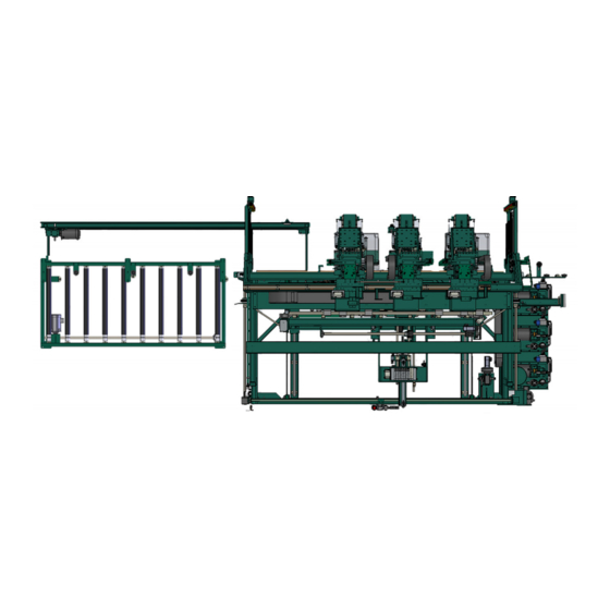
Page 32: Photo Of 990-Fx And Rts-Fx Setup
About the Machine Line Photo of 990-FX and RTS-FX Setup Below is a photo of the In-Feed area of the Production Line. 990-FX Screw Transfer Hoses RTS-FX Note: Missing Feeder. Jamb Feeder 990-FX and RTS-FX FIGURE 2-1. About the RTS-FX The RTS-FX Hopper sets are designated by Letters A, B, and C. -
Page 33: About The Jamb Transfer Machine
990-FX The Jamb Transfer will: • Feed a jamb back to the operator to load into the 990-FX • the feeding is synchronized with the 990-FX process. • The Jambs are fed by customer supplied machine. • An Out-Feed table is included •... -
Page 34: Summary Of The Controls On The Machine Line
This section describes the controls located on the machine line. About the Operator Station Touch Screen Interface: Main Con- trol of the 990-FX. Auto load and run predetermined parameters on doors. Manually control the door path and process through the line. Machine... -
Page 35: Descriptions Of Machine Controls
No changes to the parameters may be made in the off position. The key may be taken out in the off position, to prevent any inadvertent changes to the cut parameters. Set Up Lock KVAL 990-FX Operation Manual... -
Page 36: Foot Pedal And Control Box
The Six-Shooter heads will also begin to move into position. Door Auto RH / LH: Press for Auto Run, or to receive either a left-hand or right-hand incoming door. When in “Auto Door” mode, the 990-FX receives information about the incoming door from the incoming machine. -
Page 37: Hinges Loaded Button (Light Curtain Status Light)
Light Curtain Controls Hinges Loaded: Step out of the Safety Light Curtain and press this button after hinges are loaded on to the Hinge Applicators.The Light Curtain will be activated. KVAL 990-FX Operation Manual... -
Page 38: Safety Controls
If the beam is broken, the machine will shut down. This is safety feature performs the same func- tion as an Emergency Shutdown (E- Stop). For information on the E-Stop function, see “Emer- gency Shutdown and Recovery” on page 2-10 KVAL 990-FX Operation Manual 2-10... -
Page 39: To Resume Normal Operation After An Beam Is Broken
Operation of Safety Curtain FIGURE2- 5. To Resume Normal Operation after an Beam is Broken If an E-Stop is activated, use the following procedure to recover, after the cause of the emergency stop is resolved: KVAL 990-FX Operation Manual 2-11... -
Page 40: Air Brake On 990-Fx Six Shooter
Air Brake on 990-FX Six Shooter The 990-FX has air brakes on the Six Shooter assemblies. The brakes will lock the six shooter in place avoiding a crash to the head. The brakes are controlled by a lack of air pressure and will lock when the air pressure drops below a reference level. -
Page 41: Tour Of The Machine
Six Shooter from Hopper In-Feed System Lock Back Section Door is delivered from previous machine and fed Faceplate routing into 990-FX for process- and boring for lock ing. and bolt In Pocket Sensor: A through beam that Frame Node... -
Page 42: About The Front Section
• Six Shooters drop down and drill hinge into place on jamb and the door edge. Screws Transported Hoppers Six Shooter #1 Six Shooter #2 Six Shooter #3 Carriage Head #2 Carriage Head #1 Carriage Head #3 Front Section FIGURE 2-7. KVAL 990-FX Operation Manual 2-14... -
Page 43: About The Hinge Carriage
Air Driven. Router: Routs the hinge pocket on the Pre-Drill jamb and the door at the same time as the counter rotate router. Router Jamb Predrill Bits Door Predrill Bits Hinge Carriage Parts FIGURE 2-8. KVAL 990-FX Operation Manual 2-15... -
Page 44: About The Six Shooter System
Quick Change Dump Gate Screw Track- ing Plate Assembly Screw Pick-Off Cylinder Screw Pick Quick Change Off Slide Dump Con- Assembly tainer Hopper Cylinder Screw Delivery Tubes Plate Assembly Air Injected Cylinder Hopper Part Call-Outs FIGURE 2-9. KVAL 990-FX Operation Manual 2-16... - Page 45 Any adjustment may cause timing issues with the operation of the Six Shooter. If you think problems are being caused by the cylinders, please contact the KVAL Service Department for direction. Do not put Magnetized Screws in Hopper. Magnetized...
-
Page 46: About The Six Shooter Assembly
Allows the Six Shooter to the move to the side for Maintenance and Manual application of Hinges Vertical Cylinder: Drives Six Shooter Up and Down Vertical Rails: Driver Assembly: Hinge Application: Six Shooter Call-Outs FIGURE 2-10. KVAL 990-FX Operation Manual 2-18... -
Page 47: Driver Assembly
Factory set to align hinge. Latch Arm: Latch Arm Cylinder: Latches to H Block Moves latch arm in and out to secure in place. of position Six Shooter and Gear Box Call-Outs FIGURE 2-11. KVAL 990-FX Operation Manual 2-19... -
Page 48: About The Back Section
Machines Hole for Bolt Chip Out Loca- tion: Lock Bore Lock Bore Motor and Drill: Drills locks holes on the face of the door Key Assemblies on the Back Section (View from Front Section) FIGURE 2-12. KVAL 990-FX Operation Manual 2-20... -
Page 49: Back View Of Rear Section
Clamps edge of door Edge Clamp: Clamps edge of door Oil Reservoir Lock Bore Extend and Retract Cylinder Deep Lock Bore Limit Shallow Switches Retracted Key Assemblies on the Back Section (Back View) FIGURE 2-13. KVAL 990-FX Operation Manual 2-21... -
Page 50: About The Out-Feed
Hydraulic Tanks for Six to the next machine. Sen- Shooters sors detect position of Supplies hydraulic pressure to door and when to send it operate Six Shooter. out. Key Assemblies on the Out-Feed Section FIGURE 2-14. KVAL 990-FX Operation Manual 2-22... -
Page 51: About The Electrical Panels
Tour of the Machine About the Electrical Panels The 990-FX has a Main Electrical Panel and a High Frequency Panel. Below is an overview of the location of assemblies in the panels. The Main Electrical Panel: The High Frequency Panel •... - Page 52 VFD Section • Power Dist Connector • Fuses • Hinge Routere(1-4) • Face Plate Router • Feed Motor • Width Adjust Contactors and Thermal Over load Circuits • Lock Bore • Screw Drivers(1-4) • Bolt Drill KVAL 990-FX Operation Manual 2-24...
-
Page 53: Description Of The Six Light Panel
ACR Relay is latched. 24VDC This light comes on once the ACR is latch and the 24VDC power Supply is working Stop – Control Power Fourth First Start – Overload Relay Fifth Second E-Stop 24VDC – Third Sixth KVAL 990-FX Operation Manual 2-25... -
Page 54: Machine Start Summary
Machine Start Summary Machine Start Summary This is a summary of the start sequence for the 990-FX Line. Ensure factory air and power is present at the machine. For more information: See “Tour of the Machine” on page 2-13 Ensure the machine main is on. - Page 55 Machine Hand Place- ment and Warning Stickers on the Machine. Load Jamb on top of ledge pressing tightly against fence. After Jamb is secure, press the Jamb to clamp the Jamb Clamp Foot Pedal KVAL 990-FX Operation Manual 2-27...
- Page 56 Move out of area beyond Light Curtain When outside of Light Curtain, press the button to Hinge Loaded start the process. Repeat from Step (Load Jamb) until completed. Take Note of the Status Blink codes KVAL 990-FX Operation Manual 2-28...
-
Page 57: Initial Powering Operations For The 990-Fx Line
Initial Powering Operations for the 990-FX Line Initial Powering Operations for the 990-FX Line This section describes how to power up and to power down the 990-FX Line. Powering up the system includes: • Applying power to the entire system •... -
Page 58: Home The 990-Fx
The 990-FX must go through a homing routine before any operations are performed. The homing routine sets a zero reference from which the 990-FX measures its movement and cutting process. If power is lost or the 990-FX is re-set, the homing routine must be performed again to reset the zero reference... -
Page 59: How To Power Down The Machine
Initial Powering Operations for the 990-FX Line How to Power Down the Machine Push the button for each machine, located on the Stop Operator’s Station Shut down the operating system, by selecting Shutdown from the Desktop. Note: Make sure Windows is shutdown completely before turning off the machine. -
Page 60: Description Of User Interface Screens
This section describes the user interface screens. The user interface allows the operator to use a touch screen to control the door cutting process, auto-run, manually run the door, store door pro- files, and use diagnostics to help troubleshoot the 990-FX. Screen Selection Menu Map Below are the menu selections for the 990-FX. -
Page 61: Machine Feed Back
The information generated is as follows:’ General Machine Status Front Section Status Back Section Status Current Servo Positions Use this information to isolate issues if having Note: problems with the machine. KVAL 990-FX Operation Manual 2-33... -
Page 62: About The Main Screen
About the Main Screen About the Main Screen The Main Screen is also the startup screen for the 990-FX. From this screen, all the basic user interface controls are available to run a door. Main Screen FIGURE2- 17. KVAL 990-FX Operation Manual... -
Page 63: Machine Controls
Shut Down Button This button shuts down the computer. Use this button as part of the shutdown pro- cess.See “Initial Powering Operations for the 990-FX Line” on page 2-29 Exit Application Button This button shuts down Interface Program and defaults to the Windows Desktop... - Page 64 Main Screen parameters. After pressing the button: Modify Preset Select one of the gray buttons in which to save the parameters Name it to an appropriate label. Select the save button to save to memory. KVAL 990-FX Operation Manual 2-36...
- Page 65 Press to Enable or Disable the Screw Type A, B, or C: Screw types that are loaded in pickup bins. • Press to Enable or Disable the Screw Screw Drop Drops for all Six Shooters. KVAL 990-FX Operation Manual 2-37...
-
Page 66: Lock Group
Face Plate. Face Plate: Face Plate • indicates the backset distance for the each downloaded preset. Lock Backset: • Press to Enable or Disable the Ball Catch. Ball Catch (Option): KVAL 990-FX Operation Manual 2-38... -
Page 67: About Manual Operation
About Manual Operation About Manual Operation From this screen, you can control certain functions of the machine in manual mode. This screen is mainly used in troubleshooting, checking cut specifications, and maintenance. Manual Operation Screen FIGURE 2-18. KVAL 990-FX Operation Manual 2-39... -
Page 68: Jog Controls
Clamp Clamp Router: • Press and hold the button move the Router up. Release the button to Stop • : Press and hold Down to move the Router down.Release the button to Stop Down KVAL 990-FX Operation Manual 2-40... -
Page 69: Screw
Use this button if a new Chipout Block is installed on the lock section. Burn Chipout: Press to start the burn sequence. A new hole will be slowly drilled. the process will automatically stop when finished. KVAL 990-FX Operation Manual 2-41... -
Page 70: Feed
Test Mode runs the hinge cycle, but does not extend the tools. This is primarily used to verify a new template is correct and the hinge carriage will not bump into the H- Block or other assemblies. KVAL 990-FX Operation Manual 2-42... -
Page 71: About The Setup Screen
The first finger represents the positive direc- tion of the ‘Z” axis, the thumb represents the positive direction of the ‘Y” axis, then second finger represents the positive the direction of the ‘X’ axis. KVAL 990-FX Operation Manual 2-43... -
Page 72: Entering Calibration Offsets
Note: Maximum offset is 0.50 inches. If more than 0.50 inches of adjustment is needed, there is a high probability that another issue may be causing a problem. If issues can not be resolved, contact the KVAL Service Center KVAL Inc. (1-800-553-5825). See “Getting Help from KVAL” on page 1- Enter the offset positive or negative number in... -
Page 73: Calibration Steps For The Lock Location
Note the measurement value and compare to specification If the lock location is correct, there is no need to perform this process, If it is not correct, follow the instructions in See “Adjusting Lock Location” below. Reference Door Lock FIGURE 3. KVAL 990-FX Operation Manual 2-45... - Page 74 Exit Main Calibration Screen. Screw Shift Positions This menu adjusts the screw drop location. Adjusts the six shooter in or out. Use if a screw is not dropping correctly and binding up at the applicator. KVAL 990-FX Operation Manual 2-46...
- Page 75 Screw Type Positions Adjusts the hopper to bin location. If the hopper is not aligned to the pickup bin, use this control to adjust the location. Width Positions Adjust the width clamp settings. KVAL 990-FX Operation Manual 2-47...
- Page 76 Timing (Infeed and Outfeed) • This is distance the clamped door is Infeed Stop: located after the “After-Indeed eye”. • This is the distance the clamped door Out feed Stop: is located after the “Before-Out-feed eye. KVAL 990-FX Operation Manual 2-48...
-
Page 77: Diagnostic Screen
The top line will have the most current routine that is running. If the machine issue can not be resolved, call KVAL Inc. (1-800-553-5825). Have any error code that is displayed, ready to give the KVAL representative. -
Page 78: Door Count
Initial start up of the machine. Cannot be Reset. Daily: Number of doors pro- cessed through-out the day. This is additive until reset. Reset Count: Push to reset the Daily count of doors. KVAL 990-FX Operation Manual 2-50... -
Page 79: Appendix: Machine Component Terms
(3x3 pattern) Eight-Shooter The Eight -Shooter is located at the left side of the machine.Eight Shooters apply hinges and the secures them with screws. (4X4pattern) (Opt K) KVAL 990-FX Operation Manual 2-51... - Page 80 Appendix: Machine Component Terms KVAL 990-FX Operation Manual 2-52...
- Page 81 2-10, 2-31 2-33 e-stop light main electrical panel description description 2-25 2-23 main screen interface 2-34 front section manual operation key assemblies 2-15 interface 2-39 front section status menu map 2-32 KVAL 990-FX Operation Manual...
- Page 82 1-14 remote operation, setting up machine for 1-16 reset machine button description user interface 2-35 return material authorization (RMA) 1-14 returning the product to Kval 1-14 Right Hand Rule 2-43 safety guidelines Safety Sign Off Sheet Safety Concerns 1-19 service center, contacting information...
- Page 84 Contacting KVAL Customer Service Phone and Fax: Mailing address: In the U.S and Canada, call (800) 553-5825 or fax Customer Support Department (707) 762-0485 Kval Incorporated Outside the U.S. and Canada, call (707) 762-7367 825 Petaluma Boulevard South or fax (707) 762-0485 Petaluma, CA 94952 Email: service@kvalinc.com...
Need help?
Do you have a question about the 990-FX and is the answer not in the manual?
Questions and answers