Kval 700-C Service Manual
Frame assembly machine
Hide thumbs
Also See for 700-C:
- System reference manual (88 pages) ,
- Operation manual (72 pages) ,
- Operation and service manual (68 pages)

Subscribe to Our Youtube Channel
Related Manuals for Kval 700-C


Summary of Contents for Kval 700-C
- Page 1 Service Manual Published: October 18, 2023 Innovation, Quality & Honesty 700-C Frame Assembly Machine...
- Page 2 . For authorization to copy Kval Inc this information, please call at (800) 553-5825 or fax (707) 762-0485. Kval Customer Support Manual Name: 700-C Service Manua Manual Revision: 46-CS1-MV101.1, 46-CS1-MV100.2 is a trademark of Incorporated. 700-C Kval Copyright 2021 .
- Page 3 KVAL 700-CService Manual Technical Support For machinery support and troubleshooting. Call, email, contact us on our website at the “Contact Us” page. Mon-Fri:4:00 AM - 4:00 PM PST email: support@kvalinc.com Field Service Support For any other inquiries or to schedule on-site service. Call, email, contact us on our website at the “Contact Us”...
- Page 4 From there, you can easily select and download the desired files and resources. This streamlined process ensures you have quick and convenient access to the information you need for your machine Machine Support Page FIGURE 1-1. QR Code https://kvalinc.com/machine-support KVAL 700-CService Manual...
-
Page 5: Table Of Contents
..................1-10 Remove Locks ..................1-10 Perform Visual Checks ................1-10 Close the Cage Gate ................1-11 Getting Help from Kval ................1-12 Kval Return and Warranty Policy ............1-13 Send the Item ....................1-13 Acceptance of Return ................1-13 Refund Turnaround Time ................1-13 Kval Errors ....................1-13 Customer Errors ..................1-14... - Page 6 Table of Contents A Note to the Operator ................1-16 Maintenance of the 700-C...Chapter 2 Maintenance Schedule ................2-1 Lubrication Schedule ................2-3 Kval Lubrication Kit ..................2-4 About Bearings ..................2-5 About Pillow Block Bearing Housings ..........2-6 About Flange Bearing Housings ..............2-6 About Ball Rail Bearings ...............2-7...
- Page 7 Table of Contents Adjusting Cylinder Extend Speed ............3-7 Adjusting Cylinder Retraction Speed ............3-7 Pneumatic Assembly Locations ............3-8 Description of the Light Tower ............3-9 Bottom Light (Control Power) ..............3-10 Bottom Light Conditions ................3-10 If the Bottom Light is OFF ...............3-10 If the Bottom Light is ON .................3-10 Top Light (Machine Status) ..............3-11...
-
Page 9: Introduction And Safety
Introduction and Safety CHAPTER 1 This chapter provides an overview of the and important safety Kval Door Transport System (DTS) information to follow when operating the machine. Chapter 1 at a Glance Section Name Summary Page This section provides an overview of the... -
Page 10: About The 700-C
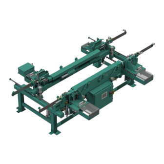
About the 700-C About the 700-C is generally used in-line with the Commander 3 or 990 Kval 700-C Frame Assembly Machine Series of machines. The operation includes placing the strike jamb and header into the machine and clamping into place. The door, with hinge jamb installed, is then moved into position, gently lowered into place, and then securely clamped into position. - Page 11 Customer requests to utilize their own staple guns and remote fires which differ from the outlined standard engi- neered models in Option SG. Note: Not all staple guns can be applied to the 700-C machine. SGS4: Stanley Bostitch Staple Replaces the standard staple guns with four(4) Stanely Bostitch SB650S4 (1/2"...
-
Page 12: About This Manual
Description Introduction Descriptions of Machine Line and Safety Information. Operation Descriptions of how to power machine line, and operator user screens. Tour Descriptions of the Table Options of the 700-C. Service Manual This Manual. Chapter Title Description Introduction Descriptions of Machine Line and Safety Information. -
Page 13: Safety First
Safety Terminology of Labels In addition to the nameplate, machines may have other warning labels or decals that provide Kval safety information to operators. Safety labels should be clearly visible to the operator and must be replaced if missing, damaged, or illegible. -
Page 14: Safety Guidelines
Safety Guidelines Safety Guidelines In addition to the caution and warning labels affixed to this machine, follow the guidelines below to help ensure the safety of equipment and personnel. Different versions of the stickers may have been applied to the machine. The Note: intent of safety is the same. -
Page 15: Lockout/Tagout Guidelines
Lockout/Tagout Guidelines Lockout/Tagout Guidelines Follow these Lockout/Tagout guidelines, • Place a tag on all padlocks. On the tag, each operator must put their own name and date. (These locks are only to be removed by the person who signs the tag) •... -
Page 16: Lockout/Tagout Procedure
Lockout/Tagout Procedure Lockout/Tagout Procedure This policy is required by OSHA regulation 1910.147 and Cal OSHA’S SB198 ruling of July 1991. Use the following lockout procedure to secure this machine while it is powered down. During a lockout, you disconnect all power and shut off the air supply. -
Page 17: Lockout/Tagout Air Supply
Lockout/Tagout Procedure push the red tab to pop it out. Place a pad- Disconnect style Electrical Panels: lock through the hole. Place your tag on the padlock, as per the tagout guide- lines below. (see illustration below). Turn Switch to the Insert Lock into hole. -
Page 18: Post Maintenance Steps
Lockout/Tagout Procedure Post Maintenance Steps After maintenance is completed, the person performing the work must ensure all tools, spare parts, test equipment, etc., are completely removed and that all guards and safety devices are installed. Before removing the locks and tags, the person who attached them shall inspect the equipment to ensure that the machine will not be put in an unsafe condition when re-energized. -
Page 19: Zero-Energy To Start-Up
Replace Guards Replace all equipment guards. If part of equipment cannot be properly adjusted after start-up with guard on, contact the See “Getting Help from Kval” on page 1-12. Kval Technical Support. Check Controls Confirm that all switches are in the “OFF” position. Please be advised that some components of the machine may start automatically when energy is restored. -
Page 20: Close The Cage Gate
Zero-Energy to Start-Up Close the Cage Gate Verify all cage gates are securely closed. Ensure all safety protocols are in effect. Zero-Energy to Start-Up 1-11... -
Page 21: Getting Help From Kval
Getting Help from Kval Getting Help from Kval Before you seek help, first try the troubleshooting procedures. Follow the procedures below. If you are unable to resolve the problem: Locate the machine’s Specification Plate and record the serial number, 3 phase volts, electrical print number, and air print number. -
Page 22: Kval Return And Warranty Policy
Kval Return and Warranty Policy Kval Return and Warranty Policy goal is to provide customers with high quality products. If, for any reason, you are not com- Kval's pletely satisfied with your purchase, please contact us at: Email: parts@kvalinc.com +1 (800) 553-5825 Phone: •... -
Page 23: Customer Errors
Kval Return and Warranty Policy Customer Errors If the item is to be returned due to customer ordering error, the customer must return the item to or the shipper of origin at its expense. A 15% restocking fee may apply to manufactured... - Page 24 Kval Return and Warranty Policy Page Intentionally Left Blank Kval Return and Warranty Policy 1-15...
-
Page 25: Safety Sign-Off Sheet
Name (print):___________________ Signature: __________________ Date:____/____/____ Supervisor/Safety Officer/Trainer Name (print):__________________Signature: __________________ Date:____/____/___ recommends you make a copy of this sheet for new operators. If a copy is Note: Kval needed, contact our at (800) 553-5825 or email at sup- Technical Support port@kvalinc.com. -
Page 27: Maintenance Of The 700-C
Lubrication Requirements ments for the machine, including types of grease to use. Definitions of bearings. page 2-5 About Bearings All bearing locations on the 700-C. page 2-8 Lubrication Map page 2-9 Carriage Bearings Bearings associated with the Staple Carriages. page 2-11 Fence Bearings Bearings associated with the Movable Fence. -
Page 28: Maintenance Schedule
Maintenance Schedule recommends the following maintenance schedule to ensure that the machine operates prop- Kval erly. Cycles refers to the quantity of processed doors. Cleaning curtails build up of sawdust and grime which causes issues with the operation of the machine. Inspecting, finds issues before they become problems. - Page 29 Inspect Inspect all airlines for kinks or rubbing. Lubricate Refill all lubricators. Replace fluid if milky or discolored. Use ab ISO 32 standard hydraulic oil (KVAL PN:SYS-LUBEG). Lubricate Grease ball screw bearings (if applicable). See “Lubrication Schedule” on page 2-3.
-
Page 30: Lubrication Schedule
Recommended Schedule Recommended Lubrication Type Linear Bearing Pillow Block (Hub) Every 250 Hours of Machine Operation Bearing Dura-Lith Grease (KVAL P/N Flange Block Bearing Lube EP-2) Ball Screw Every 80 Hours of Machine Operation Idler Shafts (Pulley) Monthly Tapered Bearing... -
Page 31: Kval Lubrication Kit
Lubrication Schedule Kval Lubrication Kit Hydraulic Oil Silicone Spray Grease Gun EP-2 Multi-FAK Grease Extension Adapter Needle Nozzle E Adapter Needle Nozzle Lubrication Kit FIGURE 2- 3. Lubrication Schedule... -
Page 32: About Bearings
About Bearings About Bearings This section describes the parts of the machine that require periodic lubrication, and specifies the lubricants. In addition, it explains how to maintain the lubrication systems on the machine. If the bearing is equipped with a grease fitting (Zerk Fitting). The Zerk fitting is basically a valve that opens under pressure to allow lubricant to pass through a channel and be forced into the voids of the bearing. -
Page 33: About Pillow Block Bearing Housings
About Pillow Block Bearing Housings About Pillow Block Bearing Housings A pillow block is any mounted bearing where the mounted shaft is in a parallel plane to the mounting surface, and perpendicular to the center line of the mounting holes, as compared to dif- ferent types of flange blocks or flange units. -
Page 34: About Ball Rail Bearings
About Ball Rail Bearings About Ball Rail Bearings are linear bearings that are attached to positioning rails. In most cases, the bear- Ball Rail Bearings ings are attached to assemblies to move them in the X,Y, or Z direction. Ball Rail Bearing Ball Rail Bearings FIGURE 2- 7. -
Page 35: Machine Lubrication Map
Machine Lubrication Map Machine Lubrication Map This machine has multiple grease points. Figure 2- 8 shows an overview of all the grease points. The following sections describe the greasing point in detail. Movable Fence Bearings Movable Fence Bearings Staple Gun Carriages –Bearings (X2) –Bearings (X2) –Horizontal Bearings (X4) -
Page 36: Greasing Staple Gun Carriage Bearings
Greasing Staple Gun Carriage Bearings Greasing Staple Gun Carriage Bearings This section details the greasing procedure for the The bearings are Staple Gun Hinge Carriage. located underneath the . The bearings provide a smooth movement in Head Staple Gun Carriage the horizontal axis and the vertical axis directions. - Page 37 Greasing Staple Gun Carriage Bearings Horizontal Bearings (X4) Vertical Bearings (X4)) Hinge Carriage Bearings FIGURE 2- 9. Greasing Staple Gun Carriage Bearings 2-10...
-
Page 38: Greasing The Movable Fence Bearings
Greasing the Movable Fence Bearings Greasing the Movable Fence Bearings This section details the greasing procedure for the The bearings are located under Movable Fence. the fence attached to the frame. The fence bearings provide a smooth movement in the horizontal axis of the . - Page 39 Greasing the Movable Fence Bearings Movable Fence Bearings (Horizontal) Hinge Carriage Bearings FIGURE 2- 10. Greasing the Movable Fence Bearings 2-12...
-
Page 40: Greasing The Rack And Pinion Bearings
Greasing the Rack and Pinion Bearings Greasing the Rack and Pinion Bearings This section details the greasing procedure for the The bearings are Rack and Pinion System. located on the feed portion of the machine The bearings provide smooth movement to adjust to the length of the incoming door. - Page 41 Greasing the Rack and Pinion Bearings Hub Bearings Hinge Carriage Bearings FIGURE 2- 11. Greasing the Rack and Pinion Bearings 2-14...
-
Page 42: Description Of Air Input System
Description of Air Input System There are two types of air inputs on machinery. Not all machines have lubricator option Kval installed. Check your machine or Air prints to verify installation. Air Input with Lubrication The air input system takes in shop air and supplies clean dry air (CDA) and lubricated air to the machine. -
Page 43: Priming The Air Line Lubricator
The approved list of oil for lubricators is as fol- lows: • P/N SYSLUBG KVAL • Chevron AW Hydraulic Oil 32 • G-C lubricants light AW R&O • Mobile DTE 24 •... -
Page 45: Troubleshooting The 700-C
A description of the operation of a pneumatic cir- page 3-5 About a Pneumatic Circuit cuit. A map of the air assembly locations on the 700-C page 3-8 Air Assembly Locations A description of the Light Tower and general trou-... -
Page 46: Get Live Technical Help
• Access to a broadband internet connection • A computer running Windows • Our remote support client Allow to logon to the machine Kval Exit the ® program. On the Windows screen, select the KVAL Service Icon KvalCAM Get Live Technical Help... -
Page 47: About A Typical Pneumatic Circuit
About a Typical Pneumatic Circuit About a Typical Pneumatic Circuit A control valve (solenoid) is used to drive cylinders to move different loads in the machine. The solenoid if controlled by the by applying a high voltage or a low voltage to a control coil. Controls for example are: extending and retracting router, drill, clamping a door. -
Page 48: Typical Pneumatic Assembly
About a Typical Pneumatic Circuit Typical Pneumatic Assembly Pneumatic assembly setups vary in machines depending on where it is used and air require- Kval ments.This is a general overview of a pneumatic assembly. See the machine’s Air Print for detailed information. Electrical Wiring Box:... -
Page 49: About Cylinder Operation
About a Typical Pneumatic Circuit About Cylinder Operation To see a block diagram of general pneumatic connections, see Figure 3- 1 on page 3-2. Figure 3- 4 below shows a cross-section of a cylinder in action. Extend Motion 1. PLC drives Control Valve. 2. -
Page 50: How The Pneumatic System Works
How the Pneumatic System Works How the Pneumatic System Works The pneumatic system consists of a brain ( ), an action (Positioning System), and a result (Moving the Load).This section describes the process to move a router to the extend and the retract position with a double valve. - Page 51 How the Pneumatic System Works Retract Process Figure 3- 6 below. If the determines the conditions are right to retract the Router directs compressed air to the retract port of the Control Valve Cylinder. retract, deactivating the cylinder router Extend Sensor When the are fully retracted, the is activated.
-
Page 52: Important Notice About Adjusting Cylinder Speed
If more than 1/2 turn on adjustment knobs are needed, call in a specialist or Note: check with at 1-800-553-5825 or start an on line ticket at Kval Technical Service https://www.kvalinc.com/support. Adjusting Cylinder Extend Speed Adjusting Cylinder Retraction Speed Tip: If Installing a new flow control assembly, shut down the flow control and back out 4 to 5 turns. this position is a good starting point for kine adjust. -
Page 53: Pneumatic Assembly Locations
Pneumatic Assembly Locations Pneumatic Assembly Locations This section shows the locations and describes the pneumatic assemblies on the 700-C Refer to the Air Schematic for machine specific information. Note: 700-C Fire Solenoid Fire Solenoid Fire Right Movable Fire Left Movable... -
Page 54: Description Of The Light Tower
Description of the Light Tower Description of the Light Tower Follow procedures before troubleshooting. See the Safety Lockout/Tagout chapter in your for steps to lockout your Operation or Service Manual machine. (High power is located in the host machine) The following checks may require the electrical panel to be opened. High Voltage is present. -
Page 55: Bottom Light (Control Power)
Bottom Light (Control Power) Bottom Light (Control Power) Control status reflects the condition of 24VDC control and the circuit associated with it. Common troubleshooting practices are described in the following section. Bottom Light Conditions The bottom light is either Location Status Link “If the Bottom Light is OFF”... -
Page 56: Top Light (Machine Status)
Top Light (Machine Status) Top Light (Machine Status) The Machine Status light reflects the condition of internal assemblies, external influences, and triggers operator interaction. Top Light Conditions The top Machine Status Light has five color conditions. Location Color Link “If the Top Light is OFF” on page 3-11 White Flashing “If the Top Light Flashing White”... -
Page 57: If The Machine Status Light Is Red
There may be an OP error. If no error codes pop up, call Kval Technical Support for assistance. They will need to hook up on- line and verify that all components are in the OP state. -
Page 58: If The Machine Status Light Is Yellow
Top Light (Machine Status) If the Machine Status Light is Yellow If the top light is yellow, an external error is possible. There are three conditions for the yellow light. See the table below. Condition Description Yellow Solid Solid yellow indicates a general error. Note: For example, a general error could be a malfunctioning dust collec- tion unit. -
Page 59: About The Three Light Panel
About the Three Light Panel About the Three Light Panel The Three Light Panel is located on the side of the Electrical Panel. If the three lights that are all illuminated, the system is in proper working order. If one or more lights are OFF, follow the process in following sections. Follow procedures before troubleshooting. -
Page 60: Start Light
About the Three Light Panel Start Light If the Start Light is on, go to the 24VDC section. Push the Start button. If the Start light remains unlit, push in the Start button and hold it in while a second person checks for voltage between #2 and #7. -
Page 61: About Switches And Sensors
About Switches and Sensors About Switches and Sensors On the Machines, the sensors and limit switches provide input to the PLC as part of the automa- tion of the door cutting process. Inputs can include feed through, door clamping, door location, and limits of movement of machine assemblies. -
Page 62: Using Sensors To Trouble Shoot
About Switches and Sensors The Limit Switch is activated by an assembly moving a switch arm. • .Depending on the model of limit switch, the amount of “pre-travel” (amount of movement from the arms resting position) is either 5 or 20 degrees before the limit switch actuates (Clicks). - Page 64 http://www.kvalinc.com...
Need help?
Do you have a question about the 700-C and is the answer not in the manual?
Questions and answers