Kval 700-C Operation Manual
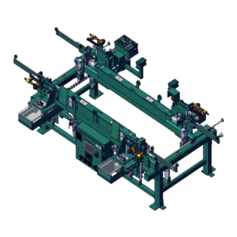
Frame assembly machine
Hide thumbs
Also See for 700-C:
- System reference manual (88 pages) ,
- Service manual (64 pages) ,
- Operation and service manual (68 pages)

Subscribe to Our Youtube Channel
Related Manuals for Kval 700-C


Summary of Contents for Kval 700-C
- Page 1 Operation Manual Published: October 17, 2023 Innovation, Quality & Honesty 700-C Frame Assembly Machine With 24 VDC Electical Panel Version...
- Page 2 (800) 553-5825 or fax (707) 762-0485. Kval Customer Support Manual Name: 700-C Operation Manua Manual Revision: 46-CS1-MV101.1, 46-CS1-MV100.2 700-C is a trademark of Incorporated. Kval Copyright 2021 . All rights reserved. Kval Incorporated ® ®...
- Page 3 KVAL 700-C Operation Manual Technical Support For machinery support and troubleshooting. Call, email, contact us on our website at the “Contact Us” page. Mon-Fri:4:00 AM - 4:00 PM PST email: support@kvalinc.com Field Service Support For any other inquiries or to schedule on-site service. Call, email, contact us on our website at the “Contact Us”...
- Page 4 From there, you can easily select and download the desired files and resources. This streamlined process ensures you have quick and convenient access to the information you need for your machine Machine Support Page FIGURE 1-1. QR Code https://kvalinc.com/machine-support KVAL 700-C Operation Manual...
-
Page 5: Table Of Contents
..................1-10 Remove Locks ..................1-10 Perform Visual Checks ................1-10 Close the Cage Gate ................1-11 Getting Help from Kval ................1-12 Kval Return and Warranty Policy ............1-13 Send the Item ....................1-13 Acceptance of Return ................1-13 Refund Turnaround Time ................1-13 Kval Errors ....................1-13 Customer Errors ..................1-14... - Page 6 Table of Contents A Note to the Operator ................1-16 Operation of the 700-C...Chapter 2 Power Operations of the 700-C ............2-1 Before Powering the 700-C ..............2-1 Powering-Up the 700-C ................2-1 Machine Status Indicators ................2-1 Powering Down the 700-C ................2-2 Before Processing a Door ..............2-3...
- Page 7 ..........3-10 Wheel Assist Cylinder ................3-11 About the Electrical Panel ..............3-12 About the High Voltage 700-C ..............3-12 About the 24 VDC Electrical Panel ............3-13 About the Machine Status Indicators ..........3-15 About the Three Light Indicator ..............3-15 About the Light Tower Indicator...
-
Page 9: Introduction And Safety
Introduction and Safety CHAPTER 1 This chapter provides an overview of the and important safety infor- 700-C Door Framing Machine mation to follow when operating the machine. Chapter 1 at a Glance Section Name Summary Page This section provides an overview of the... -
Page 10: About The 700-C
About the 700-C About the 700-C is generally used in-line with the Commander 3 or 990 Kval 700-C Frame Assembly Machine Series of machines. The operation includes placing the strike jamb and header into the machine and clamping into place. The door, with hinge jamb installed, is then moved into position, gently lowered into place, and then securely clamped into position. - Page 11 Customer requests to utilize their own staple guns and remote fires which differ from the outlined standard engi- neered models in Option SG. Note: Not all staple guns can be applied to the 700-C machine. SGS4: Stanley Bostitch Staple Replaces the standard staple guns with four(4) Stanely Bostitch SB650S4 (1/2"...
-
Page 12: About This Manual
Introduction Descriptions of Machine Line and Safety Information. Operation Descriptions of how to power machine line, and operator user screens. Tour Descriptions of the Table Options of the 700-C. Service Manual Chapter Title Description Introduction Descriptions of Machine Line and Safety Information. -
Page 13: Safety First
Safety Terminology of Labels In addition to the nameplate, machines may have other warning labels or decals that provide Kval safety information to operators. Safety labels should be clearly visible to the operator and must be replaced if missing, damaged, or illegible. -
Page 14: Safety Guidelines
Safety Guidelines Safety Guidelines In addition to the caution and warning labels affixed to this machine, follow the guidelines below to help ensure the safety of equipment and personnel. Different versions of the stickers may have been applied to the machine. The Note: intent of safety is the same. -
Page 15: Lockout/Tagout Guidelines
Lockout/Tagout Guidelines Lockout/Tagout Guidelines Follow these Lockout/Tagout guidelines, • Place a tag on all padlocks. On the tag, each operator must put their own name and date. (These locks are only to be removed by the person who signs the tag) •... -
Page 16: Lockout/Tagout Procedure
Lockout/Tagout Procedure Lockout/Tagout Procedure This policy is required by OSHA regulation 1910.147 and Cal OSHA’S SB198 ruling of July 1991. Use the following lockout procedure to secure this machine while it is powered down. During a lockout, you disconnect all power and shut off the air supply. -
Page 17: Lockout/Tagout Air Supply
Lockout/Tagout Procedure push the red tab to pop it out. Place a pad- Disconnect style Electrical Panels: lock through the hole. Place your tag on the padlock, as per the tagout guide- lines below. (see illustration below). Turn Switch to the Insert Lock into hole. -
Page 18: Post Maintenance Steps
Lockout/Tagout Procedure Post Maintenance Steps After maintenance is completed, the person performing the work must ensure all tools, spare parts, test equipment, etc., are completely removed and that all guards and safety devices are installed. Before removing the locks and tags, the person who attached them shall inspect the equipment to ensure that the machine will not be put in an unsafe condition when re-energized. -
Page 19: Zero-Energy To Start-Up
Replace Guards Replace all equipment guards. If part of equipment cannot be properly adjusted after start-up with guard on, contact the See “Getting Help from Kval” on page 1-12. Kval Technical Support. Check Controls Confirm that all switches are in the “OFF” position. Please be advised that some components of the machine may start automatically when energy is restored. -
Page 20: Close The Cage Gate
Zero-Energy to Start-Up Close the Cage Gate Verify all cage gates are securely closed. Ensure all safety protocols are in effect. Zero-Energy to Start-Up 1-11... -
Page 21: Getting Help From Kval
Getting Help from Kval Getting Help from Kval Before you seek help, first try the troubleshooting procedures. Follow the procedures below. If you are unable to resolve the problem: Locate the machine’s Specification Plate and record the serial number, 3 phase volts, electrical print number, and air print number. -
Page 22: Kval Return And Warranty Policy
Kval Return and Warranty Policy Kval Return and Warranty Policy goal is to provide customers with high quality products. If, for any reason, you are not com- Kval's pletely satisfied with your purchase, please contact us at: Email: parts@kvalinc.com +1 (800) 553-5825 Phone: •... -
Page 23: Customer Errors
Kval Return and Warranty Policy Customer Errors If the item is to be returned due to customer ordering error, the customer must return the item to or the shipper of origin at its expense. A 15% restocking fee may apply to manufactured... - Page 24 Kval Return and Warranty Policy Page Intentionally Left Blank Kval Return and Warranty Policy 1-15...
-
Page 25: Safety Sign-Off Sheet
Name (print):___________________ Signature: __________________ Date:____/____/____ Supervisor/Safety Officer/Trainer Name (print):__________________Signature: __________________ Date:____/____/___ recommends you make a copy of this sheet for new operators. If a copy is Note: Kval needed, contact our at (800) 553-5825 or email at sup- Technical Support port@kvalinc.com. -
Page 27: Operation Of The 700-C
Operation of the 700-C CHAPTER 2 This chapter describes the steps to operate the 700-C Chapter 2 at a Glance Section Name Summary Page Descriptions about powering up and power- page 2-1 Power Operations of the ing down the 700-C. -
Page 28: Before Powering The 700-C
Power Operations of the 700-C Power Operations of the 700-C Follow this procedure to power up and power down the . The powering process below 700-C includes two versions of the 700-C • 24 VDC Electrical Box Light Tower: •... -
Page 29: Powering Down The 700-C
700-C Light Tower will be lit green. \ For troubleshooting information, see the 700-C Service Note: Manual. version is included with the high voltage Three Light Box electrical panel version. In this option, the high voltage is directly delivered to the . -
Page 30: Before Processing A Door
Program the Staple Patterns Before framing a door, program the staple pattern at the interface. See “About the Touch 700-C Screen Interface” on page 2-21. Mechanical Setup Summary Before processing a door, mechanically setup the machine. • Door Width Adjust •... -
Page 31: About Door Width Adjustment
About Door Width Adjustment About Door Width Adjustment The door width adjustment is an air driven assembly that adjusts to different door widths. Follow the procedures below. Pull up the button located on the Width Adjust Main Control Panel retract the pickle forks freeing the movable fence for positioning. Grasp the handle on the and move it to the desired location indicated Movable Fence... -
Page 32: About The Door Length Adjustment
About the Door Length Adjustment About the Door Length Adjustment To adjust the end clamps for 6’8”, 7’0”, or 8’0” doors, pull the pins and move clamps to the appropriate length. Secure pin in the adjustment hole. See Figure 2- 3 below. Adjust both ends. -
Page 33: Load The Staple And Nail Guns
Load the Staple and Nail Guns Load the Staple and Nail Guns Before processing a door, verify that the staple guns and the nail guns are loaded. Staple gun and Nail Gun manufacturers may vary. Always refer to the OEM Note: operation manual for complete information. -
Page 34: How To Adjust The To Thick Jambs
How to Adjust the to Thick Jambs Set the to accept thick jambs. There are three steps to adjust to thick jambs: 700-C • At the Width Adjust Shaft, adjust collars to accept a thick spacer. • At the Staple Head, flip spacers into position. -
Page 35: Step 2: Spacer Adjustments At The Staple Heads
How to Adjust the to Thick Jambs Locate the Width Adjust Shaft Adjust the collars on the shaft to accommodate the thick spacer: a.Loosen the inner collar using the T-Handle to create space for the thicker jambs. b.Slide the outer collar against the collar bar bracket for a narrow jamb or away from the bracket to allow space for the thick jamb spacer. -
Page 36: Step 3: Stop Pin Adjustments
How to Adjust the to Thick Jambs Step 3: Stop Pin Adjustments TABLE 2-2. Part # Designator Dimensions STOP1408 Standard Jamb 1/4 X 1/4 Shank STOP1416 Thick Jamb 1/2 X 1/4 Shank Figure 2- 8 below as a reference for the following procedure. Locate the insertion point on the sides of both of the Fixed Side Carriage Heads. - Page 37 About Jamb Width Adjustment auto-adjusts to the width of the hinge and strike jambs by selecting but- 700-C Width Adjust tons at the After the desired width button is selected, a pneumatic system Main Control Panel. automatically extends or retracts jamb supports to the desired jamb width.
-
Page 38: 700-C Hands Free Control Summary
700-C Hands Free Control Summary 700-C Hands Free Control Summary The table below shows a summary of the operation of the . The table includes manual oper- 700-C ations, how to use the machine controls, and what the machine is doing during each process. - Page 39 700-C Hands Free Control Summary Descriptions Action Control Actions Press Both Hands Free Buttons. • The outfeed wheels raise the door Raise Door into Sta- pling Position into stapling position. Note: Ensure door, header jamb and • The bottom jamb clamps rise, push- strike jamb are clamped square before ing the frame up from the bottom.
-
Page 40: Before Processing A Door
FIGURE 2- 10. Using the Main Control Panel Make sure the area safe and clean. Apply power to the . See “Power Operations of the 700-C” on page 2-1. 700-C version s do not have Start and Stop buttons. Light Tower 700-C If needed, adjust the staple pattern program at the interface. - Page 41 Sequence and Staple Select controls. Step 7: B Step 7: A • Sequence is determined by the pro- gram that is created at the 700-C interface. See “About the Touch Screen Interface” on page 2-21 Step 7: E Step 7: C Step 7: C more information.
-
Page 42: Stage The Door
Step 1: Insert the Header Jamb Identity the hand of the door. “About Left Hand and Right Hand Doors” on page 2-13. Note: Partially pull the door into the 700-C Place the header jamb into Head Jamb Clamp Insert Header Jamb Header Insert FIGURE 2-11. -
Page 43: How To Frame A Door
After the door is pulled in and the hinge and striker jambs are aligned, use the Hands Free controls to staple the frame to the door. See “700-C Hands Free Control Summary” on page 2-11 for a summary of the framing operation. - Page 44 How to Frame a Door Door Lowers into Position Fine Adjust the Door Alignment Drop Door to Align FIGURE 2- 14. Step 3: Bring in the Fixed Heads Press both simultaneously. Hands Free Buttons • Fixed side staple guns move in. Bring in the Fixed Fixing Heads FIGURE 2-15.
- Page 45 How to Frame a Door • End jamb clamps move in. • Ensure that the door, header jamb, strike jamb are clamped square. Door is Secured from Below Raise the Door into Stapling Position FIGURE 2- 16. Step 5: Fire Staple Guns Press the left and the simultaneously.
- Page 46 • All guns move away from the door. • All clamps retract. • Outfeed wheels move up. • Manually move the door out of the 700-C. Unclamp Door to Move it Out FIGURE 2- 19. How to Frame a Door...
- Page 47 • goes back to the initial stage. 700-C • Last step before pulling in another door or shutting down the machine. 700-C is Ready for the Next Door Reset to Beginning Position FIGURE 2- 20. How to Frame a Door...
-
Page 48: About The Touch Screen Interface
Maintenance Screens Screen Paths Programming Screen Main Screen Manual Screen Kval Technician use only Diagnostic Screen About the Main Screen The Main Screen is the gateway to Program screens and the Diagnostic Screen. Touch the desired button on the screen to jump to that screen. -
Page 49: About The Programming Screen
Located on all screens. Select Reset if machine is paused. machine. The program will stay on the same screen, jamb size will need to be reselected, all air cylinders return to the start posi- tions. 700-C Main Screen FIGURE 2- 21. About the Programming Screen Select the desired Program Button on the Main Screen to jump to this screen. -
Page 50: How To Set Staple Location
About the Touch Screen Interface How to Set Staple Location The programming buttons determine where staples will be fired into the jamb. A gray background indicates the staple location is not active, a green background indicates the staple location is active. -
Page 51: About The Diagnostic Screen
The top line will have the most current routine that is running. If the machine issue can not be resolved, call (1-800-553-5825). Have any Kval Technical Support error code that is displayed, ready to give the . This will aid in troubleshooting and Kval Technician shorten down time. -
Page 53: Tour Of The 700-C
Take a tour of the 700-C. Chapter 3 at a Glance Section Name Summary Page This section shows locations of the 700-C page 3-1 700-C Overview assemblies. This section includes the location and descrip- page 3-2 About the Main Control tions of the controls located on the Main Panel. -
Page 54: Top View 700-C
Top View 700-C Top View 700-C This chapter describes the assemblies of the 700-C Feed Direction Right Hand Door Header Location Right Hand Movable Side Gun Head Length Adjust Right Hand Fixed Side Gun Head Main Control Panel Width Adjust... -
Page 55: About The Main Control Panel
The Main Control Panel is located next to the right hand staple head on the Movable Fence side. Figure 3- 1 below shows a panel. Table 3- 1 700-C on page 3-3 includes descriptions of the panel selec- tions. Please note that panel selections Note:... - Page 56 About the Main Control Panel Main Panel Selection Descriptions. TABLE 3- 1. Description Icon Control Control Circuit This controls the power supply for the machine, turning it on and off. Start or Stop the machine operating system. (Only located on Machine Power the on the Three Light High Voltage version.) Note: The Light Tower version does not need the Start and...
-
Page 57: About The Hands Free Controls
About the Hands Free Controls About the Hands Free Controls are located on the movable fence side next to the . The con- Hands Free Controls Main Panel trols consist of two , and a Option) Hands Free Buttons Fire Stapler Button Fire Nailer Button ( The control sequence is listed in the table below. -
Page 58: About The Staple Gun Heads
The staple guns inserts staples into the desired locations in the door frame. There are four staple guns. Two on the fixed side and two on the movable side of the labeled Right Hand-Mov- 700-C able Side, Left Hand-Movable Side, Right Hand-Fixed Side, Left Hand-Fixed Side (see illustra- tion above). -
Page 59: How The Staple Gun Movement Works
About the Staple Gun Heads Through Beam Staple Gun Trigger Bar Staple Gun Air Input Fire Guns Control Valve Air Gun Horizontal Solenoid Air Cylinders Air Gun Verti- cal Air Cylin- ders Flow Control Oil Cylinder To Shared Carriage Head Parts of the Staple Head FIGURE 3- 3. -
Page 60: About Firing Staples
Each of the four staple guns is controlled by a dedicated PLC output. See Figure 3- 4 below. staple triggering operation may vary. Depending on the option, trig- Note: 700-C 700-C gering will occur when air is removed or triggering will occur when air is applied. -
Page 61: About The Trigger Bar
About Firing Staples Beam Sensed Beam Blocked To PLC input To PLC input (O Volts) (+24 Volts) -24 Volts -24 Volts -24 Volts -24 Volts +24 Volts +24 Volts +24 Volts +24 Volts Through beams FIGURE 3- 5. About the Trigger Bar The trigger bar is a plate with 1/8”... -
Page 62: About The Feed System
There are two sections, one a mirror image of the other. One section is located on the fixed side of the , the other on the movable side. Each section consists of a 700-C • set of tandem pneumatic cylinders for the main drive • a pneumatic cylinder for wheel assist •... -
Page 63: About Tandem Cylinder Stroke Lengths
About the Feed System Dual Activated Main Air Control Valves Supply PLC output PLC output (Retract) (Retract) PLC output PLC output (Extend) (Extend) 1.5” Cylinder Common Shaft 2.5” Cylinder Tandem Cylinder Component FIGURE 3-2. About Tandem Cylinder Stroke Lengths One cylinder has a 1.5” travel, the other a 2.5” travel. This allows for four different stroke lengths of 0”, 1.5”, 2.5”... -
Page 64: Wheel Assist Cylinder
About the Feed System Wheel Assist Cylinder The wheel assists cylinder's function is to provide extra lift Wheels assist cylinder for the out-feed wheels. The wheel assist is a pneumatic cyl- inder that when activated pushes a bracket mounted on the rack. -
Page 65: About The Electrical Panel
High Voltage is present in this panel at the top of the three phase input even with the disconnect turned off. If working on the panel, follow safety protocol as described in Chapter 1. Kval recommends that high voltage troubleshooting within the panel should be performed only by trained electricians. -
Page 66: About The 24 Vdc Electrical Panel
About the Electrical Panel About the 24 VDC Electrical Panel The Figure below shows the front panel and identifies the electrical assemblies in a 24 VDC revi- sion Electrical Panel. EtherCat Connector PLC and Terminals Breaker Control Circuit 24 VDC Terminals 24 VDC Electrical Panel FIGURE 3-4. - Page 67 About the Electrical Panel Component Description PLC Kit Industrial computer. Brain of the 700-C. The Embedded PLC together with Bus Terminals receive digital and analog signals from sensors and output them to actuators or forward them to higher-level controllers. PLC Terminals Bus Terminals receive digital and analog signals from sensors and out- put.
-
Page 68: About The Machine Status Indicators
700-C Three Light Box Two Light Tower Troubleshooting information by using the indicators is located in the “700-C Note: Service Manual.” About the Three Light Indicator is located on high voltage machines on the Electrical Box. The machine is Three Light Box ready to work when all lights are illuminated. - Page 72 http://www.kvalinc.com...
Need help?
Do you have a question about the 700-C and is the answer not in the manual?
Questions and answers