
Related Manuals for Banner R-GAGE K50R


Summary of Contents for Banner R-GAGE K50R
- Page 1 K50R R-GAGE® Radar Sensor Instruction Manual Original Instructions p/n: 226219 Rev. E April 26, 2024 © Banner Engineering Corp. All rights reserved.
-
Page 2: Table Of Contents
1.1 EU Declaration of Conformity (DoC) ............................... 4 1.2 Models ........................................5 1.3 Overview........................................5 1.4 Features and Indicators................................... 6 1.5 Banner Measurement Sensor Software ..............................7 Chapter 2 Installation Instructions 2.1 Sensor Orientation....................................8 2.2 Wiring ........................................9 2.3 Mount the Device..................................... 9 Chapter 3 Getting Started 3.1 Install the Software .................................... - Page 3 Chapter 10 Product Support and Maintenance 10.1 Repairs ........................................ 40 10.2 Contact Us......................................40 10.3 Banner Engineering Corp. Software Copyright Notice ........................40 10.4 Banner Engineering Corp Limited Warranty............................40 Index ............................42 ...
-
Page 4: Chapter 1 Product Description
EU Declaration of Conformity (DoC) Banner Engineering Corp. herewith declares that these products are in conformity with the provisions of the listed directives and all essential health and safety requirements have been met. For the complete DoC, please go to www.bannerengineering.com. -
Page 5: Models
K50Rxx-4030 0.05 Dual Discrete models only The range shown is for Standard Mode. Refer to "Specifications" on page 31 for the range of Faster Response or High Power Mode. April 26, 2024 page 5 © Banner Engineering Corp. All rights reserved. -
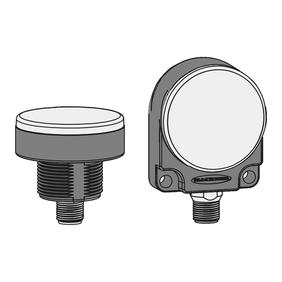
Page 6: Features And Indicators
Options include animation, intensity, patterns, colors, and others. "Configure a Pro Sensor " on page 27 for configuration information and instructions. If all LEDs flash red continually, the sensor is in an error state. page 6 April 26, 2024 © Banner Engineering Corp. All rights reserved. -
Page 7: Banner Measurement Sensor Software
• Easily monitor device status via the software • Visualize the application in real-time • Make adjustments to sensor settings on the fly For more information, visit www.bannerengineering.com/us/en/products/sensors/software/ banner-measurement-sensor-software.html. April 26, 2024 page 7 © Banner Engineering Corp. All rights reserved. -
Page 8: Chapter 2 Installation Instructions
Tilt angle of the target relative to the sensor T= Target Angle, BA=Beam Angle Orientation—K50Rxx-8060 models Figure 3. 80º 80º Alignment arrow located on side label K50RxF-8060 Models K50RxB-8060 Models April 26, 2024 page 8 © Banner Engineering Corp. All rights reserved. -
Page 9: Wiring
(1) 2 = White 3 = Blue 10–30 V DC bu (3) 4 = Black – 5 = Gray (Connect for use with remote input or Banner bk (4) Load D1_Out * Measurement Sensor software) wh (2) Load D2_Out / **PFM... -
Page 10: Chapter 3 Getting Started
Navigate to and open the downloaded file. Click Install to begin the installation process. Depending on your system settings, a popup window may appear prompting to allow the Banner Measurement Sensor software to make changes to your computer. Click Yes. - Page 11 Alternative System Components—K50RFx Model Shown Figure 6. A = Pro Converter Cable (MQDC-506-USB) B = Splitter (CSB-M1251FM1251M) C = PC running Banner Measurement Sensor software D = K50R E = Power Supply (PSW-24-1 or PSD-24-4) F = Optional 5-Pin to 5-Pin Double-Ended Cordset (ex.
-
Page 12: Software Overview
K50R R-GAGE® Radar Sensor Instruction Manual Getting Started Software Overview Easy setup and configuration of range, sensitivity, and output using the Banner Measurement Sensor software and Pro Converter Cable. Figure 7. Banner Measurement Sensor Software Navigation toolbar—Use this toolbar to connect to the sensor, to save or load a configuration, or to reset to factory defaults Live Sensor Data and Legend—Shows the signal strength versus distance for the connected sensor, as well as... -
Page 13: Chapter 4 Banner Measurement Sensor Workspace
Use these signals to evaluate targets to determine where the signal strength threshold and switch point should be configured for reliable detection. Use the Y-Axis Max and the X-Axis Max to adjust the range displayed on the plot. Legend: Use the legend to select which data appears on the graph. Signal Displays the strength of the signal over distance. April 26, 2024 page 13 © Banner Engineering Corp. All rights reserved. -
Page 14: Summary Pane
Signal Strength Threshold: The threshold for the minimum amount of signal needed to actuate the output. Target Mode: Nearest Target—Output responds to the nearest target that is over the signal strength threshold. Strongest Target—Output responds to the target with the highest signal strength that is over the signal strength threshold. Not available in the Standard performance mode. Varies by output model. page 14 April 26, 2024 © Banner Engineering Corp. All rights reserved. -
Page 15: Discrete 1 Tab
NO/NC: Select Normally Open or Normally Closed from the list. On Delay: Set an on delay in milliseconds. The maximum time is 60,000 ms. Off Delay: Set an off delay in milliseconds. The maximum time is 60,000 ms. April 26, 2024 page 15 © Banner Engineering Corp. All rights reserved. -
Page 16: Discrete 2 Tab
Switch Point: Set a single switch point for the output to change. Window: Define two setpoints to create window limits. Complementary: Output 2 is opposite of Output 1. Pulse Pro/PFM: Pulse Pro/Pulse Frequency Modulation (PFM) output to interface with Banner lights or a PLC with PFM inputs. Distance Settings Available when Output Mode is set to Switch Point or Window. - Page 17 100 Hz to 600 Hz. An output of 50 Hz or 650 Hz (user defined in the software) represents a loss of signal condition where there is no target or the target is out of range. This output can be tied directly to a number of Banner lights for visual feedback without the need for a controller.
-
Page 18: Analog Tab
17600 35200 70400 4.4.5 Indication Tab Use this tab to configure advanced indications for Pro models with configurable LEDs. "Configure a Pro Sensor " on page 27 for details. page 18 April 26, 2024 © Banner Engineering Corp. All rights reserved. -
Page 19: Live Sensor Data Controls
Record. The log file selection prompt displays. Save the log file as desired. The log file format is .csv. If communication to the sensor is lost, click Refresh Device Connection to reconnect. April 26, 2024 page 19 © Banner Engineering Corp. All rights reserved. -
Page 20: Chapter 5 Configuring A Sensor
The remote input wire is disabled by default. Pulse the remote input wire 10 times or use the Banner Measurement Sensor software to enable the feature. After enabling the remote input feature, pulse the remote input according to the diagram and the instructions provided in this manual. - Page 21 K50Rx-4030 K50Rx-8060 Response Speed Selection Fast Medium Slow Enable/Disable LEDs STANDARD MODELS LEDs Enabled LEDs Disabled PRO MODEL INDICATION MODE Four State Distance LEDs Disabled Reset to Factory Defaults April 26, 2024 page 21 © Banner Engineering Corp. All rights reserved.
-
Page 22: Remote Teach
Remote Teach Use the following procedure to teach the first and second switch points. NOTE: If Indication is disabled from the Banner Measurement Sensor software or a Pro model is being used, no LEDs are active during the following procedure. - Page 23 Use Target Selection to set the target that the output sees. NOTE: If Indication is disabled from the Banner Measurement Sensor software or a Pro model is being used, no LEDs are active during the following procedure. Access Target Selection mode. Action Result Five-pulse the remote input. The Power/Signal LED flashes. Select the desired signal threshold. April 26, 2024 page 23 © Banner Engineering Corp. All rights reserved.
-
Page 24: Reset The Sensor To Factory Defaults
To reset using the Banner Measurement Sensor software, go to Sensor › Factory Reset. The sensor indicators flash once, the sensor is reset back to the factory default settings, and a confirmation message displays. - Page 25 Factory Default Range 4 mA to 20 mA (0 V to 10 V) 4mA/0V Point 50 mm 20mA/10V Point Loss of Signal 3.5 mA (0 V) Averaging 1× (no averaging) April 26, 2024 page 25 © Banner Engineering Corp. All rights reserved.
-
Page 26: Using Measurement Hold Example
Output Measurement (green lines) holds its value for the Hold Time. After the 1 second Hold Time expires, the Output Measurement and Max Distance Change thresholds are updated based on the next Raw Measurement value. page 26 April 26, 2024 © Banner Engineering Corp. All rights reserved. -
Page 27: Chapter 6 Configure A Pro Sensor
The following colors are uncalibrated to achieve higher saturation: Red, Green, and Blue. They may show greater variance between devices than other colors. April 26, 2024 page 27 © Banner Engineering Corp. All rights reserved. -
Page 28: Distance Mode
First, define the Distance Settings. The Distance Setting is the user-defined distance that the LEDs will proportionally change from. Switch Point 1 and Switch Point 2 must be within the sensing range. page 28 April 26, 2024 © Banner Engineering Corp. All rights reserved. -
Page 29: Four State Mode
Click Write to write the parameter to the sensor. The LEDs are disabled. To enabled the LEDs, select either Distance or Four State from the Device Logic menu. Click Write to write the parameter to the sensor. April 26, 2024 page 29 © Banner Engineering Corp. All rights reserved. - Page 30 K50R R-GAGE® Radar Sensor Instruction Manual Configure a Pro Sensor The LEDs are enabled and the sensor can be configured for Distance or Four State. page 30 April 26, 2024 © Banner Engineering Corp. All rights reserved.
-
Page 31: Chapter 7 Specifications
Discrete Output 1 (Black Wire): Push/pull output, configurable PNP or NPN output Discrete Output 2 (White Wire): Configurable PNP or NPN, or Pulse Frequency Modulated (PFM) output At medium response time. April 26, 2024 page 31 © Banner Engineering Corp. All rights reserved. -
Page 32: Fcc Part 15 Class A For Intentional Radiators
Operation of this equipment in a residential area is likely to cause harmful interference in which case the user will be required to correct the interference at his own expense. page 32 April 26, 2024 © Banner Engineering Corp. All rights reserved. -
Page 33: Industry Canada Statement For Intentional Radiators
500 MB Available USB port Microsoft and Windows are registered trademarks of Microsoft Corporation in the United States and/or other countries. IMPORTANT: Administrative rights are required to install the Banner Measurement Sensor software. Dimensions All measurements are listed in millimeters [inches], unless noted otherwise. K50RxF-8060-LDQ Models Figure 15. - Page 34 M12 x 1 * [0.79] [1.57] Max. Torque 2.8 Nm (25 in-lbs) [0.37] 28.6 [1.13] Figure 17. K50RxB-4030-xxx Models Ø 50.0 [1.97] M30 x 1.5 6g M12 x 1 page 34 April 26, 2024 © Banner Engineering Corp. All rights reserved.
-
Page 35: Beam Patterns
5 cm Corner Reflector (Radar cross section = 1.5m 2 ) 90 mm Metal Pole (weak target) 90 mm Metal Pole (weak target) 1000 1000 1500 1000 1500 2000 2500 1000 1500 2000 2500 Distance (mm) Distance (mm) April 26, 2024 page 35 © Banner Engineering Corp. All rights reserved. -
Page 36: K50Rxx-4030 Models
Typical beam pattern, in degrees, on representative representative targets targets 2500 2000 1500 1000 1000 1500 2000 2500 1000 2000 3000 4000 5000 1000 2000 3000 4000 5000 Distance (mm) Distance (mm) page 36 April 26, 2024 © Banner Engineering Corp. All rights reserved. -
Page 37: Chapter 8 Update The Software
1, above, to update the software. Navigate to and open the file BannerMeasurementSensorSoftwareInstaller.exe. Depending on your system settings, a popup window may appear prompting to allow Banner Measurement Sensor software to make changes to your computer. Click Yes. Click Close to exit the installer. -
Page 38: Chapter 9 Accessories
• Right-angle bracket with curved slot for versatile orientation • Clearance for M6 (¼ in) hardware • Mounting hole for 30 mm sensor • 12-gauge stainless steel Hole center spacing: A to B=40 Hole size: A=ø 6.3, B= 27.1 × 6.3, C=ø 30.5 April 26, 2024 page 38 © Banner Engineering Corp. All rights reserved. -
Page 39: Configuration Tools
• Power Supply (PSW-24-1) Convertors R45C-PF-IQ (PFM to Analog) R45C-PF-UQ (PFM to Voltage) • Analog converter (PFM input to analog value, voltage, or current output) • Connect to sensor in-line April 26, 2024 page 39 © Banner Engineering Corp. All rights reserved. - Page 40 Banner minimum systems requirements. The above limitations apply even if Banner and its affiliates and channel partners have been advised of the possibility of such damages. This Agreement sets forth the entire liability of Banner, its affiliates and your exclusive remedy with respect to the software use.
- Page 41 K50R R-GAGE® Radar Sensor Instruction Manual Banner reserves the right to modify product specifications or update documentation at any time. Specifications and product information in English supersede that which is provided in any other language. For the most recent version of any documentation, refer to: www.bannerengineering.com.
- Page 42 © Banner Engineering Corp.
- Page 43 14, signal threshold target switch point lines nearest summary strongest distance nearest signal strength output status standard mode window strongest target sensor polarity sensor lockout X axis select target Y axis © Banner Engineering Corp.
- Page 44 LinkedIn Twitter Facebook © 2024. All rights reserved. www.bannerengineering.com...
Need help?
Do you have a question about the R-GAGE K50R and is the answer not in the manual?
Questions and answers