
Related Manuals for Banner R-GAGE K50R


Summary of Contents for Banner R-GAGE K50R
- Page 1 ® R-GAGE K50R Radar Sensor Instruction Manual Original Instructions 226219 Rev. A 11 May 2022 © Banner Engineering Corp. All rights reserved 226219...
-
Page 2: Table Of Contents
9 Accessories ..................................26 9.1 Cordsets ......................................26 9.2 Configuration Tools ..................................26 10 Product Support and Maintenance ......................... 27 10.1 Repairs ......................................27 10.2 Contact Us ....................................27 10.3 Banner Engineering Corp. Software Copyright Notice .........................27 10.4 Banner Engineering Corp. Limited Warranty ..........................27... -
Page 3: Product Description
Bright, visible indication; available in Pro models with configurable LEDs • Adjustable sensing field—ignores objects beyond setpoint • Easy setup and configuration of range, sensitivity, and output using the Banner Radar Configuration Software • Sensing functions are immune to wind, fog, steam, and temperature changes and resistant to rain and snow •... -
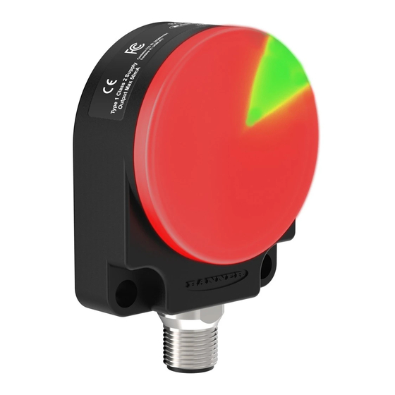
Page 4: Features And Indicators
® R-GAGE K50R Radar Sensor 1.3 Features and Indicators K50R Standard—Features Figure 2. K50RF-8060-xDQFeatures Color Description Output 1 Amber Discrete output status Power/Signal Green or Power ON and signal strength indication Strength Blue Output 2 Amber Discrete output status K50R Standard—Signal Strength and the Indicator LEDs Color Description Color... -
Page 5: Installation Instructions
2. Navigate to and open the downloaded file. 3. Click Install to begin the installation process. 4. Depending on your system settings, a popup window may appear prompting to allow Banner Radar Configuration to make changes to your computer. Click Yes. -
Page 6: Connect To The Sensor
Figure 5. System Components for a Typical Installation A = K50R B = Pro Converter Cable (MQDC-506-USB) C = PC running Banner Radar Configuration software Note: Requires a PC USB port to supply 0.5 A at 5 V. Figure 6. Alternative System Components... -
Page 7: Getting Started
6. Click Connect. The Connection screen closes and the sensor data displays. 3.2 Software Overview Easy setup and configuration of range, sensitivity, and output using the Banner Radar Configuration software and Pro Converter Cable. Figure 7. Banner Radar Configuration Software 1. -
Page 8: Banner Radar Configuration Workspace
Save a configuration to a desired location for future use. Reset Frequently Used Settings Resets the software settings without changing the configuration of the attached sensor. Exit Exit the Banner Radar Configuration Software. From the Sensor menu, the following options are available: Connect Connect to the sensor. -
Page 9: Summary Pane
® R-GAGE K50R Radar Sensor 4.3 Summary Pane The Summary pane (blue shaded area) displays Distance, Signal Strength, and Output Status. Distance Displays the distance to the target. Signal Strength Displays the amount of excess gain of the signal received from the target. The excess gain is relative to the minimum detection threshold (Signal Strength Threshold = 1). -
Page 10: Discrete 1 Tab
Switch Point: Set a single switch point for the output to change. Window: Define two setpoints to create window limits. Complementary: Output 2 is opposite of Output 1. Pulse Pro/PFM: Pulse Pro/Pulse Frequency Modulation (PFM) output to interface with Banner lights or a PLC with PFM inputs. Distance Settings Available when Output Mode is set to Switch Point or Window. -
Page 11: Indication Tab
This output can be tied directly to a number of Banner lights for visual feedback without the need for a controller. 100 Hz: Define one sensing range limit of the Pulse Pro range. -
Page 12: Configuring A Sensor
(0 V DC). The remote input wire is disabled by default. Pulse the remote input wire 10 times or use the Banner Radar Configuration software to enable the feature. After enabling the remote input feature, pulse the remote input according to the diagram and the instructions provided in this manual. - Page 13 ® R-GAGE K50R Radar Sensor Figure 8. Remote Input Map Remote Pulse Timing (T) Input Gray wire is remote teach input 0.04 seconds < T < 0.8 seconds Timing between Pulse groups > 1 second Remote Teach Teach Output 1 SPt 1 Teach Output 1 SPt 2 Teach Output 2 SPt 1 Teach Output 1 SPt 2...
-
Page 14: Remote Teach
5.2.1 Remote Teach Use the following procedure to teach the first and second switch points. Note: If Indication is disabled from the Banner Radar Configuration Software or a Pro model is being used, no LEDs are active during the following procedure. - Page 15 Set the Sensitivity Use Sensitivity Selection to set the signal strength threshold. Note: If Indication is disabled from the Banner Radar Configuration Software or a Pro model is being used, no LEDs are active during the following procedure. 1. Access Sensitivity Selection.
-
Page 16: Reset The Sensor To Factory Defaults
Target Selection Mode Use Target Selection to set the target that the output sees. Note: If Indication is disabled from the Banner Radar Configuration Software or a Pro model is being used, no LEDs are active during the following procedure. -
Page 17: Factory Default Settings
® R-GAGE K50R Radar Sensor 5.3.1 Factory Default Settings Table 3: General Tab Default Settings Setting Factory Default Response Speed Medium Signal Strength Threshold Target Mode Nearest Target Measurement Hold Disabled Discrete Output & Remote Input Remote Input Wire Disabled LED Indicators Enabled Table 4: Discrete 1 Tab Default Settings... -
Page 18: Using Measurement Hold Example
® R-GAGE K50R Radar Sensor 5.4 Using Measurement Hold Example Figure 9. Measurement Hold Raw Measurement Output Measurement Maximum Distance Decrease 1 sec 1 sec Maximum Distance Increase <1 sec Time (s) The Hold Time is set to 1 second. The Max Distance Change threshold (red lines) adapts based on the previous Raw Measurement sample (blue lines) as long as that sample was within the previous thresholds. -
Page 19: Configure A Pro Sensor
® R-GAGE K50R Radar Sensor 6 Configure a Pro Sensor The Pro sensor models offer advanced indication of distance thresholds and device states. Use the options on the Indication tab to configure the desired LED options. Color 1 and Color 2 The following colors are available for Color 1 and Color 2. -
Page 20: Distance Mode
® R-GAGE K50R Radar Sensor Pattern The Pattern control sets the pattern of the flash animation. Pattern Description Normal Alternating Color 1; Color 2 at 50% duty cycle Strobe Continuous Color 1; Color 2 flashes at 20% duty cycle 3-Pulse Three consecutive Color 1 pulses at 10% duty cycle on Color 2 background Short pulse, short pulse, short pulse, long pulse, long pulse, long pulse,... -
Page 21: Four State Mode
® R-GAGE K50R Radar Sensor Distance Settings—Match Distance Settings Discrete 1—The distance matches the distance settings of Discrete 1. If Discrete 1 is in Output Mode Switch Point, the sensing window is 0.1 m to Switch Point 1. If Output Mode is Window, the sensing window is between Switch Point 1 and Switch Point 2. -
Page 22: Specifications
Contains FCC ID: 2AQ6KA1001 4 mm from 100 to 250 mm Contains IC: 24388-A111 8 mm from 250 mm to 800 mm for others, contact Banner Engineering 16 mm from 800 mm to 2.5 m Advanced Capabilities Maximum Output Power... -
Page 23: Fcc Part 15 Class A
.NET Hard Drive Space USB Port 500 MB Available USB port Important: Administrative rights are required to install the Banner Radar Configuration software. 7.4 Dimensions All measurements are listed in millimeters [inches], unless noted otherwise. Ø50 [1.95] 2 x Ø5.5 [0.20]... -
Page 24: Beam Patterns
® R-GAGE K50R Radar Sensor 7.5 Beam Patterns The beam pattern of the radar sensor is dependent on the radar cross section (RCS) of the target. The beam pattern graphs are guides for representative object detection capabilities based on different sized radar cross sections and corresponding example real world targets. -
Page 25: Update The Software
1, above, to update the Software. 3. Navigate to and open the file BannerRadarConfigInstaller.exe. 4. Depending on your system settings, a popup window may appear prompting to allow Banner Radar Configuration Software to make changes to your computer. Click Yes. -
Page 26: Accessories
® R-GAGE K50R Radar Sensor 9 Accessories 9.1 Cordsets 5-Pin Threaded M12 Cordsets with Shield—Single Ended Model Length Style Dimensions Pinout (Female) MQDEC2-506 2 m (6.56 ft) 44 Typ. MQDEC2-515 5 m (16.4 ft) Straight MQDEC2-530 9 m (29.5 ft) M12 x 1 ø... -
Page 27: Product Support And Maintenance
This software is protected by copyright, trade secret, and other intellectual property laws. You are only granted the right to use the software and only for the purposes described by Banner. Banner reserves all other rights in this software. For so long as you have obtained an authorized copy of this software directly from Banner, Banner grants you a limited, nonexclusive, nontransferable right and license to use this software. - Page 28 Index response time 10 advanced target 9 maximum active sensing range 9 maximum distance decrease 9 maximum distance increase 9 select target 16 measurement hold 9 sensor lockout 9 minimum active sensing range 9 complementary 10 sensor polarity 9 mode Sensor Settings 9–11 distance 20 signal 8...
Need help?
Do you have a question about the R-GAGE K50R and is the answer not in the manual?
Questions and answers