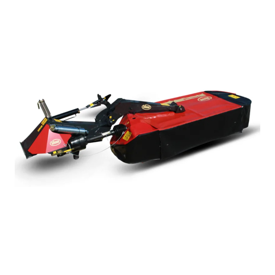
Summary of Contents for Vicon Extra 328
- Page 1 Extra 328-332-336-340 Assembly instructions Translated from the original assembly manual Version 01.2013 Date printed 02.2013 Language Document number KT19001203EN Index number 2013-01...
- Page 2 INSTRUCTIONS FOR RECIPIENTS These instructions describe how to unpack and assemble the machine. The machine is split into main components which are out together using these assembly instructions. Follow the order for assembly given in the instructions and use the size and type of bolt shown for assembling the parts - see the symbols below.
- Page 3 Contents The meaning of the symbols Contents This symbol indicates tips additional information. This warning triangle indicates important safety information and dangers. If this is not complied with, it can lead to: • Serious errors with the machine's operation. • Damage to the machine.
- Page 4 Assembly The transport safety device is removed from Assembly the hitch. Fit the hitch on the tractor. Connect the hydraulics to the tractor. Remove the springs from the chain. Pull in the cord. Activate the tractor's hydraulic system and swivel the arm down.
- Page 5 Assembly Remove the bolt and bushing from the arm. Apply oil or grease to the bushings. 58.237.000 Inject some grease or viscous oil into the groove for the O-ring on both sides of the hinged points on the arm. ...
- Page 6 Assembly Model 340 only Fit the bracket. M10x30 M12x40 Fit the guard. M10x25...
- Page 7 Assembly Fit the tarpaulin. Fit the shock absorber. M10x25 M10x60 M10x55 Attach the tarpaulin...
- Page 8 Assembly Fit the arm on the cutting unit. The machine's cutting unit can be moved 130 mm so that the attachment point is moved as shown. When the attachment point is moved, the PTO shaft is shortened. See the Instruction manual for further instruc- tions.
- Page 9 Assembly Fit and secure the steel wire on the cutting unit. Fit the PTO shaft onto the bevel gear. Remember that the friction clutch on the PTO shaft must be fitted with the bevel gear.
- Page 10 Assembly Secure the PTO shaft with the chain. Fit the PTO shaft onto the cutting unit. Do not forget the clamping ring! Fit and secure the guard on the cutting unit. Rotate the sleeve so that the lubrication hole in the universal joint is turned as shown.
- Page 11 Assembly Raise the machine's cutting unit. Fit the chain on the arm with the number of chain links shown in the diagram. Model Recommended chain link 12-13 11-12 9-10 Parking catch Swivel the parking catch over. • The support leg comes down.


Need help?
Do you have a question about the Extra 328 and is the answer not in the manual?
Questions and answers