Table of Contents
Advertisement
Quick Links
Advertisement
Table of Contents

Subscribe to Our Youtube Channel
Related Manuals for ICT MPS Ultra


Summary of Contents for ICT MPS Ultra
- Page 1 MPS Ultra Instruction Manual 855-340-032...
- Page 2 MPS Ultra SAFETY GUIDELINES Principles of Safe Operation and Maintenance Safety must always be the top priority of all personnel involved in the installation, operation, and maintenance of this unit as it operates at high voltages that could be potentially lethal. Technicians must adhere to the appropriate standards and manufacturer’s recommendations to minimize...
- Page 3 MPS Ultra General Alerts Risk of serious personal injury or damage to equipment and property. Always observe the following: • Install and operate unit in a restricted access location. A restricted access location is an area to which access can be...
- Page 4 • Consult with manufacturers of surge suppression devices to select appropriately rated protection device(s) and proper installation methods. • ICT’s product warranty does not cover damage caused by power surges and electrostatic discharge events including lightning. 855-340-032_Rev2.01_Instruction Manual...
- Page 5 MPS Ultra NOTE: Due to the breaker-detection circuitry internal to the unit, it may be possible to measure a voltage on the terminal(s) with no load connected, even if that terminal’s breaker is open circuit. This is normal operation. The breaker-detection circuitry is a high- impedance circuit, and while a voltage may be present on the output terminal, it is a signal voltage and does not support loading.
- Page 6 Innovative Circuit Technology Ltd. Disclaimer ICT shall not be held liable for any damage or injury involving this product if it has been subjected to misuse and exposure to environmental conditions not conforming to the product’s limits of operation, improper installation, or maintenance.
- Page 7 MPS Ultra ICT LIMITED WARRANTY The warranty period on ICT products is two (2) years from date of purchase from an authorized ICT reseller or OEM with valid proof of purchase, or from date of shipment from the ICT manufacturing facility. The warranty period for a repaired product or part is ninety (90) days or the remainder of the unexpired term of the new product warranty period, whichever is greater.
- Page 8 MPS Ultra In no event shall ICT be liable for any special, indirect, or consequential damages such as, but not limited to, loss of use, business or goodwill, loss of revenue, or loss of profits, which may result, either directly or indirectly, from defects in products provided by ICT.
-
Page 9: Table Of Contents
MPS Ultra TABLE OF CONTENTS 1.0 INTRODUCTION ................... 1 System Components and Features..........1 1.1.1 Intelligent Control Module (ICM) ........2 1.1.2 Power Module ..............2 1.1.3 Battery Management Module (BMMD) ......2 1.1.4 Load Distribution Module (LDM) ........3 1.1.5 Power Chassis ............... - Page 10 Regulatory Specification ............78 Mechanical Specifications ............79 9.0 GLOSSARY ..................80 LIST OF FIGURES Figure 1. A Typical MPS Ultra Configuration ............1 Figure 2. Typical Rear View ..................6 Figure 3. The BMMD ..................... 10 Figure 4. The BMMDP ................... 10...
- Page 11 Figure 5. Installing breaker with even pressure ............. 12 Figure 6. Installing breaker with uneven pressure ..........12 Figure 7. Installing Power Module in a MPS Ultra ..........13 Figure 8. The DC Output Bus Bars ................ 16 Figure 9. The LDM....................16 Figure 10.
-
Page 12: Introduction
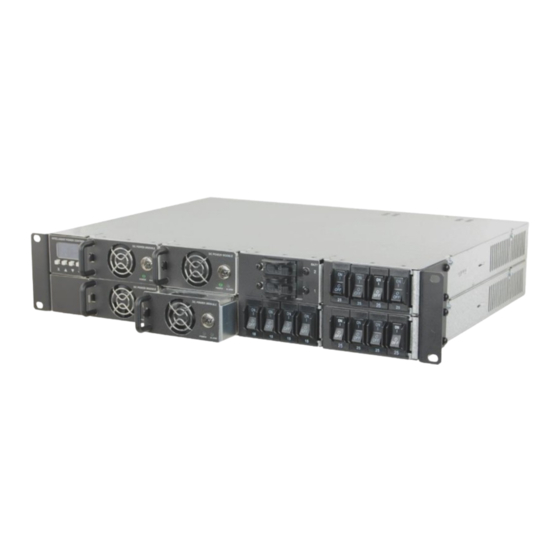
MPS Ultra 1.0 INTRODUCTION The MPS Ultra is a flexible, N+1 redundant DC power system with intelligent networked control, advanced battery management, and managed load distribution options in a pre-configured 2RU rack mount chassis. The power chassis features a factory-installed Intelligent Control Module (ICM) with... -
Page 13: Intelligent Control Module (Icm)
MPS Ultra 1.1.1 Intelligent Control Module (ICM) • High resolution OLED display with intelligent front panel controls fully integrated into power chassis • TCP/IP Ethernet communications port • Embedded web server with easy-to-use graphical user interface (GUI) • Intelligent monitoring, reporting and control of system and all installed modules •... -
Page 14: Load Distribution Module (Ldm)
Two rack-mounting ears (installed) • Four bolt/washer/nut sets for connections to the output bus bars (in bag) • Remote battery temperature sensor (ICT-TMP) included when a BMMD is installed in the system (in bag) • RJ11 data cable (ICT-JMP) (in bag) 855-340-032_Rev2.01_Instruction Manual... -
Page 15: Tools And Parts Needed
MPS Ultra 2.2.1 Tools and Parts Needed • Two 7/16-inch wrenches • Wire stripper • Four #10-32 Phillips screws (length to be decided by installer) to connect rack ears to rack • #2 Phillips screwdriver for the rack-ear connections and output bus bar cover •... -
Page 16: Table 2. Power Chassis Models
MPS Ultra Table 2. Power Chassis Models Model No. Model No. Description (negative V output) (positive V output) Intelligent Power Chassis with integrated Control Module and Ethernet communications, includes dual 100 A ICT-2U4 ICT-2U4P battery disconnect breakers and 150 A Low Voltage Disconnect, 12 x 25 A (max.) -
Page 17: Rack Mounting
De-energize the system before making any change to the wiring and connections. WARNING All DC outputs of ICT’s DC power systems are isolated from chassis ground (floating). DC output returns can remain isolated from ground (DC-I) or can be grounded (DC-C), as per site grounding requirements and/or local or national electrical codes. -
Page 18: Sensor And Alarm Connections
This is sourced from "National Electrical Code 2005 Edition" , p. 70-112. 2.7 Sensor and Alarm Connections 1. The ALARM connector allows the MPS Ultra to report faults to an external monitoring device through a form-C contact. If needed, connect form-C contact monitoring wiring to the ALARM connector as shown in Table 6. -
Page 19: Table 7. Remote Input Connector
BMMD-equipped system, for use with lead-acid batteries only) to the AUX connector as shown in Table 7. This will allow the MPS Ultra to compensate for the output voltage according to the battery temperature. Use 22–26 AWG wire. -
Page 20: Battery Connections
MPS Ultra 2.8 Battery Connections Risk of serious personal injury or damage to equipment and property. Observe the following: • Use a battery with rating and capacity appropriate for the model of power supply in use. • Use an appropriate DC overcurrent protection device in line with the backup battery connection. -
Page 21: Figure 3. The Bmmd
The optional BMMD dual breaker module provides a convenient and safe way to connect an external lead-acid or lithium-ion backup battery to the MPS Ultra. A 100-amp hydraulic-magnetic circuit breaker provides overcurrent protection, while an internal 150-amp LVD contactor will disconnect the battery should it discharge below a voltage level which is set in the Battery Backup section of the GUI. -
Page 22: Installation Of The Breakers
MPS Ultra NOTE: Use wire and connectors appropriately rated for the highest possible system current when making connections to the battery, BMMD, and power chassis. 3. Connect the battery hot lead (see comment on polarity above) to the BMMD BAT bus bar, and the battery return lead to the main system output bus bar of the corresponding polarity (i.e., a positive... -
Page 23: Installation Of The Power Module
MPS Ultra Figure 5. Installing breaker with even pressure Figure 6. Installing breaker with uneven pressure 2.10 Installation of the Power Module Risk of personal injury or damage to equipment and property. Always observe the following: • Ensure the unit has the correct polarity for the application (see Table 2). -
Page 24: Figure 7. Installing Power Module In A Mps Ultra
(the system may be powered while swapping modules). The latch is located under the module handle (see Figure 7). 4. Install an optional blanking plate (ICT-BPM) into any unused Power Module positions to prevent accidental access to the internal circuitry of the system. -
Page 25: System Wiring Final Verification
3. Install the protective bus bar cover(s) using the screws provided. 2.12 AC Power Source Connections AC input wiring to the MPS Ultra unit must be protected using an outlet with a branch rated circuit breaker of 40 amps or lower value. -
Page 26: Software Configuration
DC-AC inverter in this way may void the product warranty. Do not connect DC-AC inverters to the outputs of the Load Distribution Module of the ICT units. 1. De-energize the unit to allow safe modification of the connections. 2. Make connections to the load using wire and connectors appropriately rated for the maximum output current capability of the unit. -
Page 27: Figure 8. The Dc Output Bus Bars
MPS Ultra Figure 8. The DC Output Bus Bars If using the DC output bus bars, connect the load "Return" to either the "POS" bus bar for a negative power system or "NEG" bus bar for a positive power system (see Figure 8). Connect the load output to the other bus bar. -
Page 28: Energize Loads And Battery Connections
= POS V, for +24, or +48 V configured systems). 2. Verify the polarity of the MPS Ultra. 3. Connect up to four external loads using appropriately rated wire inserted and secured into the four cage-clamp output connector pairs on the LDM module rear panel. -
Page 29: Operation: Front Display Panel
POWER LED is lit on each Power Module; and that the Intelligent Control Module (ICM) front graphic display is lit. The MPS Ultra will start up and operate at the factory default settings when AC power is connected, generally requiring no other set up or adjustment for basic operation. -
Page 30: Menu Structure
MPS Ultra 3.2 Menu Structure See the complete menu structure in the following diagram. Navigate through the various screens using the four interface buttons. MAIN SCREEN SYSTEM STATUS SYSTEM SETTINGS INPUT VOLTAGE 120V OUTPUT VOLTAGE 55.2V ADJUST SETTINGS OUTPUT VOLTAGE 55.2V... -
Page 31: Figure 13 (Cont'd). Icm Menu Structure (Cont'd From Previous Page)
MPS Ultra LDM MODULE X LDM MODULE X SETTINGS LDM MODULE X CHANNEL ENABLE CHANNEL 1 8.0A CHANNEL ENABLE CHANNEL 1 CHANNEL 2 2.5A CHANNEL OVERCURRENT CHANNEL 2 CHANNEL 3 CHANNEL UNDERCURRRENT CHANNEL 3 CHANNEL 4 3.5A CHANNEL 4 ADJUST SETTINGS... -
Page 32: System Status
MPS Ultra 3.2.1 System Status The main system status screen will show the most current operating conditions for the unit, primarily the Input Voltage (VAC), the Output Voltage (VDC), and the total Output Current (A). Other information will be shown depending on the operating state of the unit: •... -
Page 33: Battery Management Module (If Installed)
MPS Ultra Voltage and Current Limit (see System Settings section) to match the battery type and system load requirements if required. 3.2.2 Battery Management Module (if installed) The BMMD Status Screen indicates the Battery Voltage (VDC), the combined Battery Current, and the approximate battery State of Charge (%) for lead-acid batteries or a bar graph showing relative magnitude of the total battery current for lithium-ion batteries. -
Page 34: Table 14. Default Disconnect Voltage Settings
MPS Ultra Scroll to highlight the parameter or sub- menu to change. • LVD Disconnect V • LVD Reconnect V • Charge Current Limit • Overcurrent Alarm level • Battery Type • Battery Capacity (Ah) rating • Battery discharge rate (hrs.) used for capacity spec. -
Page 35: Table 15. Default Reconnect Voltage Settings
MPS Ultra Table 15. Default Reconnect Voltage Settings Module ICT700-12PM ICT700-24PM ICT700-48PM ICT1500-24PM ICT1500-48PM Threshold Voltage 12.5 VDC 25.0 VDC 50.0 VDC Table 16. The Minimum Difference Between Disconnect and Reconnect Voltage 12 VDC Units 24 VDC Units 48 VDC Units 1.5 V... - Page 36 TEMP-CO/cell (only available for lead-acid batteries): Ensure the Battery Temperature Sensor (ICT-TMP) is installed and connected to the battery case (see Section 2.7) for optimal lead-acid battery charging and best battery life. Set the "Temperature Compensation/°C" level per battery cell to match the recommendation of the battery manufacturer (−4 mV/°C per cell is typical).
- Page 37 MPS Ultra Press Enter to select. Use the Up/Down buttons to adjust setting, press Enter to set value and return to previous screen. Press Back to return to previous screen without saving changes. DISCHARGE TEST (only available for lead-acid batteries): Configure the "Battery Discharge Test"...
-
Page 38: Load Distribution Module (If Installed)
MPS Ultra NOTE: A Battery Discharge Test of a fully charged battery can be manually initiated by changing the discharge test Status parameter to "Enabled". 3.2.3 Load Distribution Module (if installed) The LDM Status screen shows the output current for each of the four outputs. -
Page 39: Alarm Inputs
MPS Ultra Scroll to highlight the sub-menu to change (Output Undercurrent). Press Enter to select. Scroll to highlight Output to be adjusted. Press Enter to select. Use the Up/Down buttons to adjust setting, press Enter to set value and return to previous screen. -
Page 40: Alarm History
MPS Ultra 3.2.5 Alarm History The Alarm History screen displays a log of the 20 most recent alarm events. These alarms may have been raised by any module experiencing an alarm, or by one of the four external Alarm Inputs being triggered. - Page 41 MPS Ultra Advanced Options Use the Advanced Options screen to set or clear the LCD Password, Comm Control Restart and Reset Comm Settings. Scroll to choose parameter or sub-menu. • LCD Password Setup • Comm Control Restart • Reset Comm Settings •...
- Page 42 MPS Ultra RESET COMM SETTINGS: Reset the admin password, port settings, and IP address to the factory defaults by pressing the "YES" button in the Reset Comm Settings. Press Enter button. Scroll to choose. Press Enter or Back to exit with no change.
-
Page 43: Notification Screens
MPS Ultra 3.2.7 Notification Screens Alarm Notification When the unit triggers an alarm, the front display panel will be over-written by the Alarms Active screen. Press Back to return to the previous screen, press Enter to jump to the Alarm History screen. -
Page 44: Status Indicators And Alarms
MPS Ultra 3.4 Status Indicators and Alarms The status of the MPS Ultra is indicated on the front display panel module on units equipped with an ICM, or via the network GUI (see Section 4) on remotely monitored units. It is also available through SNMP (see Section 4.7.2). -
Page 45: Table 18. Battery Management Module (Bmm) Alarms
MPS Ultra Alarm Trigger Condition Module Green Alarm Send Condition Output Relay E-mail Internal bus voltage out of Disabled Shutdown range Internal aux Module Fault voltages out of Disabled Active range Over Temp Internal temp too Disabled Active Shutdown high... -
Page 46: Table 19. Load Distribution Module (Ldm) Alarms
MPS Ultra Table 19. Load Distribution Module (LDM) Alarms Alarm Output Alarm Send Trigger Condition Condition Relays Required Relay E-mail Module Power Loss of AC and DC bus Open Failure connection Normal Operation, No Alarms Closed outputs enabled Circuit Breaker... -
Page 47: Operation: Graphical User Interface
The default username is "admin", and no password is required as the factory default. To log out of the ICT MPS Ultra GUI, click on the Logout link on the top right of the browser window. The system will also automatically log off the user after 20 minutes of inactivity. -
Page 48: System
MPS Ultra 4.2 System Once successfully logged in, the System tab will be shown in the browser. 4.2.1 STATUS This tab provides the operating status of the unit. DC Output Output Status: Shows status of the DC output. Will show Enabled if providing DC output or Disabled if not. - Page 49 This number represents both batteries if this is a dual BMM (BMMD). Battery Temperature: Shows the temperature measured on the optional ICT Battery Temperature Probe (ICT-TMP). Net Ah Count: Shows the Ah that have been consumed from the battery. Will display 0 Ah if the batteries are fully charged.
-
Page 50: Settings & Contol
MPS Ultra Module #x: Load Distribution If the optional Load Distribution Module (LDM) is installed, this section will show the status of the four LDM outputs; the section will be labelled with the module number. Output #x: Shows name and status of the output. Will show amps of current being drawn. -
Page 51: Power Modules
MPS Ultra Restart Delay" field) This feature can be used to remotely force connected equipment to re-boot. Output Settings Output Voltage: Set the system "Output Voltage" to match the float voltage requirement for the external battery. The default setting varies based on the Power Modules installed (see Table 8). -
Page 52: Battery Backup (If Installed)
MPS Ultra The graphic will display green for an installed Power Module that is working as expected; a red display for an installed Power Module that has an active alarm; and will be grey when a Power Module is not installed in that slot. -
Page 53: Status
This number represents both batteries if this is a dual BMM (BMMD). Battery Temperature: Shows the temperature measured on the optional ICT Battery Temperature Probe (ICT-TMP). If no probe is installed, the unit will default to 25°C. Net Ah Count: Shows the Ah that has been consumed from the battery. -
Page 54: Settings & Contol
MPS Ultra LVD Status: Shows the status of the LVD (Open or Closed). Alarm Status: Shows status of the batteries (Alarm or OK). 4.4.2 SETTINGS & CONTOL This tab is used to adjust the settings of the BMM. Always consult battery manufacturer's specifications when selecting battery type. - Page 55 The default setting is 0 mV/°C. NOTE: The system must have the battery temperature sensor (ICT- TMP) installed on the battery for this setting to have an effect (default setting is 0 mV, assumes 25°C operation).
-
Page 56: Table 21. Default Equalize Voltage Settings
MPS Ultra Set up manual or automatic equalize charge cycles for flooded lead-acid batteries. This setting is only available if the system is configured for use with a lead-acid type battery. The connected load devices should continue to run normally while the equalization charge is running. - Page 57 MPS Ultra Day of Week: Set the day of the week that the automatically recurring equalize charge should take place or select "Any" to allow an equalize charge to take place on any day of the week. Day of Week takes precedence over Equalize Interval.
-
Page 58: Table 22. Default Disconnect Voltage Settings
MPS Ultra Disconnect Voltage: Set the threshold to a level that will protect the battery from excessive discharge (as recommended by the battery manufacturer). The LVD contactor will open when the battery discharges to this level for at least 3 seconds. The default setting varies based on the Power Modules installed. - Page 59 MPS Ultra Battery Over-Current Alarm Over-Current Threshold: Set the threshold to receive an alarm notification when the battery discharge or charge current exceeds a set overcurrent level. Set the threshold to 0 amps to disable this alarm. The default setting is 0 (Disabled).
-
Page 60: Table 26. Default Discharge Voltage Limit Settings
MPS Ultra discharge to no more than 50% of the nominal battery capacity to avoid stressing the battery due to a deep discharge. This setting is only available if the system is configured for use with a lead-acid type battery. - Page 61 MPS Ultra Discharge Test Interval: Set the time in days (0–180 days) between automatic discharge tests. Set this time to 0 to disable automatic discharge tests. The default setting is 0 (Disabled). Day of Week: Set the day of the week that the automatically recurring discharge test should take place or select "Any"...
-
Page 62: Load Distribution (If Installed)
MPS Ultra NOTE: System will state that the discharge test is Not Ready if the battery SOC is less than 100%. Last Battery Discharge Test: Shows the date and time that the last discharge test was performed. Status: Displays the end status of the last discharge test (Complete or Fail). -
Page 63: Status
MPS Ultra 4.5.1 STATUS This tab shows the operating status and current loads of the circuit-breaker controlled outputs on the LDM module. If there is more than one LDM installed, they will show individually. Module Status Shows the slot that the LDM is installed in and the status (Alarm or OK). - Page 64 MPS Ultra Master Output Control Select "All Outputs On" or "All Outputs Off" to turn on or off all four output channels simultaneously. The default setting is Enabled. Module Setup Power-On Sequencing / Power Cycling Delay Time: Set the time in seconds (0–60 seconds) that will be used as the delay between energizing outputs.
- Page 65 MPS Ultra Select an Output to edit Select the output to be edited in this section. Make any required changes, and then click on the Save Settings button at the bottom of the page to save any edits. Output Settings Output Label: Enter a descriptive label for the selected output channel.
- Page 66 MPS Ultra Output Load-Shedding Load shedding will disable specified outputs when the system DC voltage reaches a preset threshold for at least 30 seconds. This will save battery capacity for mission-critical load devices by turning off non-critical load devices. Loads will be reconnected if "Load-Shedding Auto Recovery" is enabled, and the DC voltage exceeds the "Recovery Threshold"...
-
Page 67: Alarms
MPS Ultra Output Over-Current Alarm Over-Current Threshold: Set the current that will trigger an overcurrent alarm on this output. Output current above this level for at least 5 seconds will trigger the Over-Current Alarm. Disable this alarm by setting the threshold to 0 amps. The default setting is 0 (Disabled). -
Page 68: Status
MPS Ultra 4.6.1 STATUS This tab shows all active alarms and up to 32 historic alarms. The history will be cleared after the ICM is rebooted. Active Alarms Shows the module that the alarm is on; the name of the alarm; the time that the alarm started and the status of the alarm (ACTIVE). -
Page 69: Communications
MPS Ultra Alarm Input # Alarm Name: Set a meaningful name to suit the installation (these will be used for e-mailed alarm messages). Contact Type: Set the form-C behavior for each device to be monitored (Not Used, Normally Open, Normally Closed). Select Not Used for all unused alarm input channels. - Page 70 MPS Ultra Model: Shows the model number, series name, and voltage configuration. Hardware: Shows the hardware version. Serial Number: Shows the serial number. Date and Time Settings Current System Time: Shows the current system date and time. Synchronize with NTP Server: Select the check box to synchronize with NTP Server.
- Page 71 MPS Ultra may require rebooting to re-establish communications with the unit. The default is Disabled. Primary IP Address: Set a primary IP address for the unit to ping to determine whether the network is functioning. Secondary IP Address: Set a secondary IP address for the unit to ping to determine whether the network is functioning.
-
Page 72: Network Setup
MPS Ultra 4.7.2 NETWORK SETUP Use this tab to configure the unit’s network settings. Saving any changes to the network settings will cause the ICM to re-start, causing momentary loss of communications. NOTICE Network MAC Address: Shows the MAC address assigned to the unit. It is also shown on the LCD Network Status screen. - Page 73 MPS Ultra Web Server Changing the web server port numbers may cause loss of communication with the unit. NOTICE The following ports may be changed within a range of 1 to 65,565, if required. HTTP Port: Set the port used for HTTP traffic between the unit and the browser.
- Page 74 LDM channel outputs only. • Full Device Control: Allows SNMP client to set all unit settings through SNMP. This setting requires a different MIB file which can be downloaded from the ICT Website: https://www.ict- power.com/resources/tools-utilities/. 855-340-032_Rev2.01_Instruction Manual Page 63 of 80...
- Page 75 MPS Ultra SNMP Contact Information: Set contact information, such as an operator name and phone number for the unit, which can be read via SNMP queries (this information is optional). v1/v2c Settings Read Community: Enter the community string/password here for read- only SNMP access.
-
Page 76: E-Mail Setup
MPS Ultra Trap Community: Set the community string/password that will be sent with all SNMPv1 traps. Some trap receivers can filter based on Trap Community. This field is only used for v1 traps. Trap User Name: Set the username for SNMPv3 traps. This field is only used for v3 traps. - Page 77 MPS Ultra Use this tab to configure all e-mail settings to enable automatic e-mail notifications directly from the unit. The information required for this is available from the Network Administrator, or Internet Service Provider (ISP). E-mail SMTP Server: Set the name or the IP address of the SMTP server used for sending outgoing e-mail (e.g., “smtp.gmail.com”).
-
Page 78: User Setup
MPS Ultra AC Input Power is lost: Select this check box to receive an e-mail notification when the AC input drops below a functional level. A Power Module failure occurs: Select this check box to receive an e-mail notification when any of the installed Power Modules stop functioning. - Page 79 MPS Ultra Record the new password(s) for future access. If the Administrator password is lost the unit must be reset to return the password to the blank default setting, causing loss of all other NOTICE user settings (see Section 3.3).
-
Page 80: Maintenance
MPS Ultra Add New User User Name: Set user name. Access Level: Set access level. Password: Set password. Password (confirm): Confirm password. Confirm Changes User Name: Enter admin user name to confirm these changes are valid. Password: Enter the password for the admin name to confirm the changes are valid. - Page 81 The export does not include Administrator password, Network nor Web Server settings. Use the Import Settings section on other systems to locate this file and then import it to any other MPS Ultra. 855-340-032_Rev2.01_Instruction Manual Page 70 of 80...
- Page 82 MPS Ultra Firmware Update Download the latest MPS Ultra firmware file from the ICT website (ict- power.com) to a local computer. Select the "Update Firmware" button to access the Firmware Update page shown below. Use this page to update the firmware on the power system control module by clicking the "Choose File"...
-
Page 83: Help
4.8 Help This tab has helpful links to ICT’s website. Instruction Manual Click the "HERE" button to download the ICT MPS Ultra Instruction Manual from the ICT’s website. SNMP Click the "HERE" button to download the SNMP MIB file. -
Page 84: Operation: Parallel (Not Applicable)
Check the network cable connections to the unit and the network. • Ensure the network card settings on the computer are configured for accessing the IP address of the MPS Ultra. To access a unit 855-340-032_Rev2.01_Instruction Manual Page 73 of 80... - Page 85 MPS Ultra with the default IP address of 192.168.0.180 the typical network settings for the computer are: IP Address: 192.168.0.100 Subnet Mask: 255.255.255.0 Gateway: 192.168.0.1 • If the HTTP port of the unit has been changed, append the new port number to the URL used to access the unit (see Section 4.7.2).
- Page 86 7.10 How do I log out of the GUI? To log out of the ICT MPS Ultra GUI, click on the Logout link on the top right of the browser window. The system will also automatically log off the user after 20 minutes of inactivity.
-
Page 87: Product Specifications
MPS Ultra 8.0 PRODUCT SPECIFICATIONS 8.1 Electrical Specifications Table 27. Overall Electrical Specifications Parameters Rating AC Input Nominal Rating 120 / 240 VAC; 50 / 60 Hz AC Input Operating Range 108 to 264 VAC AC Input Maximum Range 90 to 300 VAC Input Power Factor (typical) 0.99 (120 VAC input) - Page 88 MPS Ultra Power Parameters 700- 700- 700- 1500- 1500- Chassis 12PM 24PM 48PM 24PM 48PM Output Power (max) 6,300 W 700 W 700 W 700 W 900 W 900 W (115 VAC) @ N+1 Output Current 350 A 50 A 25 A 12.5 A...
-
Page 89: Physical Specifications
MPS Ultra 8.2 Physical Specifications Table 29. Physical Specifications Parameters Configuration Power Modules are floating, may be connected with Output Grounding Positive or Negative ground Alarm Output Form-C contact, 0.5 A 60 VDC max DC Connectors: Bus Bar, 5/16-inch bolt hole... -
Page 90: Mechanical Specifications
MPS Ultra 8.4 Mechanical Specifications Table 31. Dimension and Weight Physical Property Value Dimension - L x W x H 15.7 x 19.0 x 3.5 in. (398 x 483 x 89 mm) Weight 30 lbs. (13.6 kg) maximum Weight of unit as shipped with BMMD and LDM. No Power Modules. -
Page 91: Glossary
MPS Ultra 9.0 GLOSSARY • Two Rack Unit; 3.5-inch (89 mm) of rack height • A, amps Amperes • Amperes (Root Mean Square) • Advanced Encryption Standard • Ampere-Hours • ANSI American National Standards Institute • Address Resolution Protocol •... - Page 92 Find the latest version of this manual here: https://ict-power.com/product/mps-ultra-dc-power-system/ INNOVATIVE CIRCUIT TECHNOLOGY LTD. 26921 Gloucester Way Langley, British Columbia, Canada V4W 3Y3 T +1 604.856.6303 (International) T +1 877.930.0717 (North America Toll-free) www.ict-power.com...
Need help?
Do you have a question about the MPS Ultra and is the answer not in the manual?
Questions and answers