Table of Contents
Advertisement
Quick Links
Advertisement
Table of Contents

Subscribe to Our Youtube Channel
Related Manuals for ICT PRT-PSU-DIN-2A


Summary of Contents for ICT PRT-PSU-DIN-2A
- Page 1 PRT-PSU-DIN-2A Protege DIN Rail 2A Intelligent Power Supply Installation Manual...
- Page 2 Copyright © Integrated Control Technology Limited 2003-2021. All rights reserved. Last Published: 30-Apr-21 3:50 PM PRT-PSU-DIN-2A | Protege DIN Rail 2A Intelligent Power Supply | Installation Manual...
-
Page 3: Table Of Contents
Core Temperature on Output Load Operation Inputs Trouble Inputs Outputs Online Mode Programmable Outputs Offline Mode AC Fail Status Output Battery Fail Status Output Intelligent Monitoring Monitoring Setup Address Configuration LED Indicators PRT-PSU-DIN-2A | Protege DIN Rail 2A Intelligent Power Supply | Installation Manual... - Page 4 UL and ULC Installation Requirements UL/ULC Installation Cabinet Options ULC Compliance Requirements CAN/ULC-S304 CAN/ULC-S319 CAN/ULC-S559 UL Compliance Requirements UL1610 UL294 FCC Compliance Statements Industry Canada Statement Disclaimer and Warranty PRT-PSU-DIN-2A | Protege DIN Rail 2A Intelligent Power Supply | Installation Manual...
-
Page 5: Introduction
900M (3000ft). Further span can be achieved with the use of a network repeater module. The current features of the power supply include: ⦁ Industry standard DIN rail mounting ⦁ Online and remote upgradeable firmware Secure encrypted RS-485 module communications ⦁ PRT-PSU-DIN-2A | Protege DIN Rail 2A Intelligent Power Supply | Installation Manual... -
Page 6: Installation Requirements
The National Electrical Code, ANSI/NFPA 70 ⦁ The Canadian Electrical Code, Part I, CSA C22.1 ⦁ AS/NZS 2201.1 Intruder Alarm Systems ⦁ The Local Authority Having Jurisdiction (AHJ) ⦁ PRT-PSU-DIN-2A | Protege DIN Rail 2A Intelligent Power Supply | Installation Manual... -
Page 7: Grounding Requirements
(RS-485 N+, N-, NA, NB) DIN Rail Enclosure Additional DIN Rail Enclosure(s) Controller Reader Expander Dialer’s Earth Ground Connection Input Expander Power Supply Output Expander AC Mains Wiring Earth Ground Link Connection PRT-PSU-DIN-2A | Protege DIN Rail 2A Intelligent Power Supply | Installation Manual... - Page 8 Sector or Building #3 Note that the DIN rail enclosure earth terminal is connected to the power supply V- terminal. There must be only one single earth grounding point per system. PRT-PSU-DIN-2A | Protege DIN Rail 2A Intelligent Power Supply | Installation Manual...
-
Page 9: Mounting
When the tamper input is triggered, trouble input AExxx:01 on the power supply will be opened. Tamper Input Connection: Tamper Switch Bracket V2+ V- V1+ V- BATT OK AC OK 12VDC OUTPUT 2 12VDC OUTPUT 1 TAMPER FORM B CONTACTS (50mA max) PRT-PSU-DIN-2A | Protege DIN Rail 2A Intelligent Power Supply | Installation Manual... -
Page 10: Vibration Sensor
Terminals 3 and 4. N.C. alarm output contacts, with built in 10 ohm resistor in series. 12V (Screw terminal 1). 0V (Screw terminal 2). Alarm circuit. N/C contact. (Screw terminals 3&4). PRT-PSU-DIN-2A | Protege DIN Rail 2A Intelligent Power Supply | Installation Manual... -
Page 11: Modes Of Operation
With the unit in momentary operation (See Modes of Operation: Dual stage linear sensitivity above), use a terminal screwdriver to turn the sensitivity control fully clockwise to maximum (Position 6). PRT-PSU-DIN-2A | Protege DIN Rail 2A Intelligent Power Supply | Installation Manual... - Page 12 Repeat this process until the unit only just responds to the desired impact. Replace the sensor cover, tighten the fixing screw and check its response to the desired impact. PRT-PSU-DIN-2A | Protege DIN Rail 2A Intelligent Power Supply | Installation Manual...
-
Page 13: Wiring Diagram
Core temperature within 15°C of Over Temp Shutdown. 12VDC Electric Locking Device Core temperature OK. 1N4007 Diode Output current exceeded. Over Current Shutdown Activated. Over Current Maximum output current not exceeded. PRT-PSU-DIN-2A | Protege DIN Rail 2A Intelligent Power Supply | Installation Manual... -
Page 14: Ac Power Supply
⦁ Extra care must be taken when wiring the AC inputs. Improper connection will cause permanent damage to the power supply. PRT-PSU-DIN-2A | Protege DIN Rail 2A Intelligent Power Supply | Installation Manual... -
Page 15: Backup Battery
To comply with EN 50131-1 only one battery can be connected and monitored per system. If more capacity is required a single larger battery must be used. PRT-PSU-DIN-2A | Protege DIN Rail 2A Intelligent Power Supply | Installation Manual... -
Page 16: Backup Battery Thresholds
Backup Battery Thresholds The battery disconnection threshold is 8V. Upon reconnection of mains power the power supply automatically detects the backup battery and begins controlled charging at 500mA (typical). PRT-PSU-DIN-2A | Protege DIN Rail 2A Intelligent Power Supply | Installation Manual... -
Page 17: Encrypted Module Network
Technical Specifications section of this manual: Maximum total output current, ⦁ AUX DC output current, ⦁ Controller bell DC output current, and ⦁ Total combined current ⦁ PRT-PSU-DIN-2A | Protege DIN Rail 2A Intelligent Power Supply | Installation Manual... -
Page 18: Module Wiring
NB terminals of the first and last modules on the RS-485 network. These are the modules physically located at the ends of the RS-485 network cabling. First Module on RS-485 Network Last Module on RS-485 Network 330R 330R From Next Previous Module Module PRT-PSU-DIN-2A | Protege DIN Rail 2A Intelligent Power Supply | Installation Manual... -
Page 19: Output Load Connection
Core Temperature on Output Load Operation The table below helps illustrate how the core temperature of the power supply module influences the operation of the V1 and V2 outputs. PRT-PSU-DIN-2A | Protege DIN Rail 2A Intelligent Power Supply | Installation Manual... - Page 20 Core Temperature Output Load Operation Status <70°C 70-80°C >80°C Outputs Enabled (Mains Power) Outputs Supplied by Battery Output Over-Current Failure Trouble Input Activated Over-Current Output Shutdown Activated PRT-PSU-DIN-2A | Protege DIN Rail 2A Intelligent Power Supply | Installation Manual...
-
Page 21: Inputs
The power supply emulates an analog expander module on the Protege module network. This means that all programming, trouble input and output information is stored in and reported by the analog expander records when programming via a Protege keypad or Protege software. PRT-PSU-DIN-2A | Protege DIN Rail 2A Intelligent Power Supply | Installation Manual... -
Page 22: Outputs
Upon restoring AC power, the output relay will revert back to its default state (normally closed). PRT-PSU-DIN-2A | Protege DIN Rail 2A Intelligent Power Supply | Installation Manual... -
Page 23: Battery Fail Status Output
The outputs used for both the AC fail and battery fail status outputs are rated for low power use only (50mA, 12V Max). Incorrect use may cause erroneous faults or serious damage to the Power Supply and will VOID ALL WARRANTIES OR GUARANTEES. PRT-PSU-DIN-2A | Protege DIN Rail 2A Intelligent Power Supply | Installation Manual... -
Page 24: Intelligent Monitoring
However, this will create a large number of events and should only be used for verifying the reception of data. For more information on programming this feature, see the Protege GX Operator Manual. PRT-PSU-DIN-2A | Protege DIN Rail 2A Intelligent Power Supply | Installation Manual... -
Page 25: Address Configuration
The controller has a set limit on the number of modules of each type that it can support. When adding and configuring modules always refer to the Maximum Module Addresses table in the controller installation manual. PRT-PSU-DIN-2A | Protege DIN Rail 2A Intelligent Power Supply | Installation Manual... -
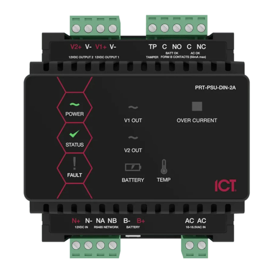
Page 26: Led Indicators
V1 Output/V2 Output Indicators The V1 output and V2 output indicators shows the status of the 12VDC output. State Description Constantly on 12VDC output operating OK Constantly off 12VDC output failure PRT-PSU-DIN-2A | Protege DIN Rail 2A Intelligent Power Supply | Installation Manual... -
Page 27: Battery Indicator
The over current indicator will show the status of the output current for both V1+ and V2+. State Description On (red) Output current exceeded. Over Current Shutdown Activated Maximum output current not exceeded PRT-PSU-DIN-2A | Protege DIN Rail 2A Intelligent Power Supply | Installation Manual... -
Page 28: Error Code Indication
The serial number in the device is not valid. Return the unit to the distributor for replacement. Locked Device The module or system controller is a locked device and cannot communicate on the network. Return the unit to the distributor for replacement. PRT-PSU-DIN-2A | Protege DIN Rail 2A Intelligent Power Supply | Installation Manual... -
Page 29: Mechanical Diagram
Mechanical Diagram The mechanical diagram shown below outlines the essential details needed to help ensure the correct installation of the power supply. PRT-PSU-DIN-2A | Protege DIN Rail 2A Intelligent Power Supply | Installation Manual... -
Page 30: Mechanical Layout
The mechanical layout shown below outlines the essential details needed to help ensure correct installation and mounting. All measurements are shown in millimeters. 78.40 Front 78.40 39.20 39.20 Back 67.18 PRT-PSU-DIN-2A | Protege DIN Rail 2A Intelligent Power Supply | Installation Manual... -
Page 31: Technical Specifications
It is important that the unit is installed in a dry cool location that is not affected by humidity. Do not locate the unit in air conditioning or a boiler room that can exceed the temperature or humidity specifications. PRT-PSU-DIN-2A | Protege DIN Rail 2A Intelligent Power Supply | Installation Manual... -
Page 32: Maximum Total Output Current: Ul And Ulc Installations
Integrated Control Technology continually strives to increase the performance of its products. As a result these specifications may change without notice. We recommend consulting our website (www.ict.co) for the latest documentation and product information. Maximum Total Output Current: UL and ULC Installations The following table describes the maximum total output current available for standby operation using an external VRLA battery in order to comply with UL and ULC standby requirements. -
Page 33: New Zealand And Australia
New Zealand and Australia General Product Statement The RCM compliance label indicates that the supplier of the device asserts that it complies with all applicable standards. PRT-PSU-DIN-2A | Protege DIN Rail 2A Intelligent Power Supply | Installation Manual... -
Page 34: European Standards
Power Supply Type A (EN 50130-4 ed. 2) Mains supply voltage variations (EN 50130-4 ed. 2) Mains supply voltage dips and short interruption (EN 50130-4 ed. 2, EN 61000-4-2 ed. 2) PRT-PSU-DIN-2A | Protege DIN Rail 2A Intelligent Power Supply | Installation Manual... - Page 35 To comply with EN 50131-1 only one battery can be connected and monitored per system. If more capacity is required a single larger battery must be used. PRT-PSU-DIN-2A | Protege DIN Rail 2A Intelligent Power Supply | Installation Manual...
-
Page 36: Ul And Ulc Installation Requirements
Control units that support auto arming shall provide an audible signal throughout the protected area not less than 10 min prior to the auto arming taking place. The control unit shall allow authorized users to cancel PRT-PSU-DIN-2A | Protege DIN Rail 2A Intelligent Power Supply | Installation Manual... - Page 37 The Contact ID Reporting Service must be enabled and the Service Mode must be configured to start with the operating system. Refer to the section Contact ID in the Operator Reference Manual. PRT-PSU-DIN-2A | Protege DIN Rail 2A Intelligent Power Supply | Installation Manual...
- Page 38 Products or components of products, which perform communications functions only, shall comply with the requirements applicable to communications equipment as specified in CAN/CSA-C22.2 No. 60950-1, Information Technology Equipment Safety - Part 1: General Requirements. Where network interfaces, such PRT-PSU-DIN-2A | Protege DIN Rail 2A Intelligent Power Supply | Installation Manual...
-
Page 39: Can/Ulc-S319
Fail secure locking mechanisms shall only be installed where allowed by the local authority having jurisdiction (AHJ) and shall not impair the operation of panic hardware and emergency egress. PRT-PSU-DIN-2A | Protege DIN Rail 2A Intelligent Power Supply | Installation Manual... -
Page 40: Can/Ulc-S559
Controller | Options in the Operator Reference Manual. The Test Report Time is Periodic option must be enabled. Refer to the section Controller | Options the Operator Reference Manual. PRT-PSU-DIN-2A | Protege DIN Rail 2A Intelligent Power Supply | Installation Manual... - Page 41 When installed with the power supply manufactured by Marcus, Model M4758CT, the Littelfuse Part No. 150322 fuseholder and Littelfuse Part No. 0312005 5A, 3AG fast-acting fuse must be installed in-line to the Power Supply. PRT-PSU-DIN-2A | Protege DIN Rail 2A Intelligent Power Supply | Installation Manual...
- Page 42 TROUxLE Programmable vOM4ST*TUS4r4Fx Output u4The4*v4F*IL4output4on4the4Power4Supply4MUST4be4programmed4to4follow4the4*v4Trouble4Input4as4followsD *v4F*IL4,4OPEN4on4fail u4Fire4areas4shall4be4separated4from4burglar4areas4through4area4partitioningi u4Fire4Inputs4ZoqZm4shall4be4used4exclusively4for4fire4monitoring4and4cannot4be4programmed4to4activate4the4bell4output u4Fire4Input4Z:4NiO4Push4xutton4to4be4used4as4monitoring4reset4switchi Typical4Input4vircuits EOL Resitor Input Configuration Niv4Input4vontact Value4o Value4l Monitored4Status Tamper Value4l Value4o Opene4vlosee4Tampere4Short Opene4vlosee4Tampere4Short Opene4vlosee4Tampere4Short Opene4vlosee4Tampere4Short Opene4vlosee4Tampere4Short Opene4vlosee4Tampere4Short 4uEOL4resistor4must4be4installed4at4the4Fire4*larm4vontrol4Panel4Outputi PRT-PSU-DIN-2A | Protege DIN Rail 2A Intelligent Power Supply | Installation Manual...
- Page 43 All fire area inputs must be placed into an area and this area must be armed. Please refer to the section Inputs | Areas and Input Types in the Operator Reference Manual. ⦁ COM Status PRT-PSU-DIN-2A | Protege DIN Rail 2A Intelligent Power Supply | Installation Manual...
-
Page 44: Ul Compliance Requirements
The Contact ID Reporting Service must be enabled and the Service Mode must be configured to start with the operating system. Refer to the section Contact ID in the Operator Reference Manual PRT-PSU-DIN-2A | Protege DIN Rail 2A Intelligent Power Supply | Installation Manual... -
Page 45: Ul294
A bell or visual indicator used as an arming acknowledgment signal must be listed to a UL security, signaling or fire standard. If intended to be mounted outside, it must be rated for outdoor use. PRT-PSU-DIN-2A | Protege DIN Rail 2A Intelligent Power Supply | Installation Manual... - Page 46 (Installation Instruction No. 29001877 R0) instead of the programmable AC indication method described above, which must be installed within a conduit knockout of the enclosure in order to provide green AC power on indication. Refer to AC Power Supply (see page 14). PRT-PSU-DIN-2A | Protege DIN Rail 2A Intelligent Power Supply | Installation Manual...
-
Page 47: Fcc Compliance Statements
NOTE: THE GRANTEE IS NOT RESPONSIBLE FOR ANY CHANGES OR MODIFICATIONS NOT EXPRESSLY APPROVED BY THE PARTY RESPONSIBLE FOR COMPLIANCE. SUCH MODIFICATIONS COULD VOID THE USER’S AUTHORITY TO OPERATE THE EQUIPMENT. PRT-PSU-DIN-2A | Protege DIN Rail 2A Intelligent Power Supply | Installation Manual... -
Page 48: Industry Canada Statement
Industry Canada Statement ICES-003 This is a Class A digital device that meets all requirements of the Canadian Interference Causing Equipment Regulations. CAN ICES-3 (A)/NMB-3 (A) PRT-PSU-DIN-2A | Protege DIN Rail 2A Intelligent Power Supply | Installation Manual... -
Page 49: Disclaimer And Warranty
Integrated Control Technology Ltd nor its employees shall be liable under any circumstances to any party in respect of decisions or actions they may make as a result of using this information. In accordance with the ICT policy of enhanced development, design and specifications are subject to change without notice. - Page 50 Disclaimer: Whilst every effort has been made to ensure accuracy in the representation of this product, neither Integrated Control Technology Ltd nor its employees shall be liable under any circumstances to any party in respect of decisions or actions they may make as a result of using this information. In accordance with the ICT policy of enhanced development, design and specifications are subject to change without notice.
Need help?
Do you have a question about the PRT-PSU-DIN-2A and is the answer not in the manual?
Questions and answers