
Related Manuals for Epever HP3522-AH1250P65A


Summary of Contents for Epever HP3522-AH1250P65A
- Page 1 Inverter/charger User Manual HP3522-AH1250P65A HP3542-AH0650P65A HP5542-AH1050P65A...
-
Page 3: Table Of Contents
Contents Important Safety Instructions Disclaimers 1 General Information 1.1 Overview 1.2 Appearance 1.3 Naming rules 1.4 Connection diagram 2 Interface 2.1 Indicator 2.2 Buttons 2.3 Home screen 2.4 Interface 2.4.1 Real-time data interface 2.4.2 User interface 2.4.3 Administrator interface 2.5 Parameters setting 2.5.1 Parameters list 2.5.2 Battery work modes 2.5.3 Battery voltage control parameters (Smart) - Page 4 3.3 Mounting the inverter/charger 3.4 Wiring the inverter/charger 3.5 Operate the inverter/charger 4 Working modes 4.1 Abbreviation 4.2 Battery mode 4.2.1 Scenario A: Both PV and Utility are not available. 4.2.2 Scenario B: PV is available, but the Utility is not available. 4.2.3 Scenario C: Both PV and Utility are available.
-
Page 5: Important Safety Instructions
Important Safety Instructions Please reserve this manual for future review. This manual contains all the safety, installation, and operation instructions for the HP-AHP65A series inverter/charger ("inverter/charger" referred to as this manual). 1. Explanation of symbols To enable users to use the product efficiently and ensure personal and property safety, please read the related words carefully when you encounter the following symbols in the manual. - Page 6 4. Safety cautions before installation When receiving the inverter/charger, please check if there is any damage in transportation. If you find any problem, please contact the transportation company or CAUTION our company in time. When installing or moving the inverter/charger, follow the instructions in the manual.
- Page 7 7. Safety cautions for inverter/charger operation When the inverter/charger works, the shell will generate much heat, and the WARNING temperature is very high. Please do not touch it, and keep it far from the equipment susceptible to high temperature. SURFACE ...
- Page 8 Improper maintenance of the inverter/charger may cause personal injury or equipment damage; It is recommended to wear an antistatic wrist strap or avoid unnecessary contact with the circuit board. The safety mark, warning label, and nameplate on the inverter/charger should be visible, not removed or covered.
-
Page 9: Disclaimers
Disclaimers The warranty does not apply to the following conditions: Damage caused by improper use or inappropriate environment (it is forbidden to install the inverter/charger in flammable, explosive, dust accumulative, or other severe environments). The actual current/voltage/power exceeds the limit value of the inverter/charger. ... -
Page 10: General Information
1 General Information 1.1 Overview The HP-AHP65A series is an IP65 high protection level product. It supports utility charging, oil generator charging, solar charging, utility output, inverter output, and energy management. It supports parallel operation for multiple units (12 units in standard application, more than 12 units need to be customized) in single phase and three phase, with 220VAC single phase or 380VAC three phase AC output. - Page 11 Lithium battery communication port to perform the safe charging and discharging. Lithium battery self-activation. ① Parallel operation in single phase or three phase for 12 units in standard application PFC technology reduces the demand on the power grid capacity. ...
-
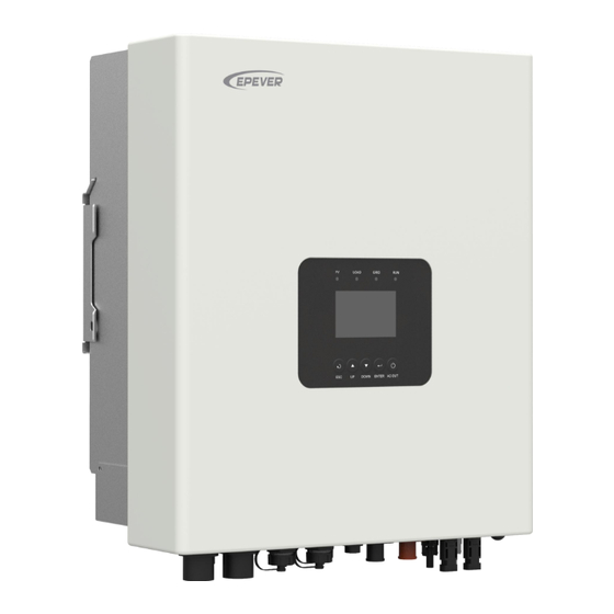
Page 12: Appearance
1.2 Appearance HP3522-AH1250P65A ... - Page 13 HP3542-AH0650P65A ...
- Page 14 HP5542-AH1050P65A ...
- Page 15 ❼ ⓮ Cooling fan Battery terminals (HP3522-AH1250P65A, HP5542-AH1050P65A) (1) Dry contact specification: 1A@125VAC, 2A@30VDC. Function: The dry contact interface is connected with the generator switch to turn on/off the generator. (2) Connecting with the RS485 communication port, an optional WiFi or 4G module can remote control the inverter/charger.
-
Page 16: Naming Rules
RS485-A RS485-B RS485-B Please go to EPEVER official website to download the currently supported BMS manufacturers and the BMS parameters. (4) USB port: Update the inverter/charger’s software after connecting the inverter/charger with a computer by a standard USB com. Cable (Note: This port is for engineer debugging only and is not open to the end-user). -
Page 17: Connection Diagram
1.4 Connection diagram No battery mode ... - Page 18 Battery mode AC loads shall be determined according to the output power of the inverter/charger. WARNING The load exceeding the maximum output power may damage the inverter/charger. For different battery types, confirm the relevant parameters before power on. ...
-
Page 19: Interface
2 Interface Note: The display screen can be viewed clearly when the angle between the end-user's horizontal sight and the display screen is within 90°. If the angle exceeds 90°, the information on the display screen cannot be viewed clearly. 2.1 Indicator Indicator Status... -
Page 20: Buttons
2.2 Buttons Buttons Operation Instruction Exit the current interface. Click Switch from the "home screen" to the "Main Table Data Information" screen. Browse interface: Up/Down. Click Parameters setting interface: Increase or decrease the parameter value per step size. Parameters setting interface: Increase or decrease Press and hold the parameter value per 10 times the step size. -
Page 21: Home Screen
2.3 Home screen Instruction ❶ Display the system time, current battery type, and charging stage. When the BMS communication is normal, the icon will be shown on the far right, while when it is abnormal, the icon will be shown on the same position. ❷... -
Page 22: Interface
battery) ❼ Parallel status icon. It shows when there is two or more inverter/chargers connect in parallel successfully, and it will not display on the single inverter/charger. ★ When the PV array charges the battery, the equalizing charging is performed on the 28th of each month by default (the date can be modified). -
Page 24: User Interface
2.4.2 User interface After powering on the inverter/charger, the home screen shows up. Click the "ESC" button to enter the "Main Table Data Information" screen. Click the "ENTER" button to enter the next interface, or click the "UP/DOWN" button to browse the current screen display. "User Data Setup"... -
Page 25: Administrator Interface
2.4.3 Administrator interface After powering on the inverter/charger, the home screen shows up. Press and hold the "ENTER" button to enter the password interface. Input the password correctly (0000 by default) to check all parameters or modify them. -
Page 26: Parameters Setting
2.5 Parameters setting 2.5.1 Parameters list Enter the "Set Data Navigation" interface according to chapter 2.4.3 Administrator interface. Then click the "UP/DOWN" button to select navigation 1~9 for detail settings. Default parameters and setting ranges are shown in the following table. Note: On the parameter setting interface, click the "UP/DOWN"... - Page 27 Parameters Default User define User define: DISABLE, ENABLE UnbalanceSet (Current DISABLE Note: The parameter will only take effect when unbalance set) used in three phase. User define:Single, Phase A, Phase B, Phase C Note: After phase set is changed, must turn off Phase Set Single the inverter charger for 10 seconds before...
- Page 28 100.0A charging current) Namely, the maximum current at the battery end when the utility charges the battery. User define: 5.0~110.0A for HP3522-AH1250P65A, step size: 0.1A 110.0A Namely, the maximum current at the battery end when the utility charges the battery.
- Page 29 (Battery 100.0A step size: 0.1A. Namely, the maximum allowable Max. charging current) charge current on battery side. User define: 5.0~120.0A for HP3522-AH1250P65A, 120.0A step size: 0.1A. Namely, the maximum allowable charge current on battery side. User define: 10.0~175.0A for HP3542-AH0650P65A, 175.0A...
- Page 30 Parameters Default User define User define: VOLT, SOC VOLT: The battery voltage control parameters take effect after setting this value as “VOLT.” SOC: The SOC parameters take effect after setting ChargeControlMode (Battery VOLT this value as “SOC.” charge control mode) (Voltage) Note: If "SOC"...
- Page 31 Parameters Default User define It takes effect after the “ChargeControlMode” is set as “SOC.” LwEgyDnctRecvrSoc (Low User define: (Under energy alarm Soc+5%)~60%, or energy disconnect recover Soc) 20%~60%, step size: 1% Note: Take the maximum value between (Under energy alarm Soc+5%) and 20%. It takes effect after the “ChargeControlMode”...
- Page 32 Parameters Default User define User define: OFF, ON This parameter is for manual equalizing charging. Manual Equalize When set to "ON", the inverter/charger enters the manual equalizing charging working mode. ResetSocCalculate (Reset Soc Press the ENTER button to reset, the SOC will be calculate) automatically recalculated.
- Page 33 Parameters Default User define User define: ALL SINGLE, ALL MULTIPLE, Auto Product with two or more PV inputs is “ALL MULTIPLE” by default. When two or more PV arrays are independently input, the value shall be set to "ALL SINGLE." When two or more PV arrays are MULTIPLE connected in parallel as a single input to the PV Mode...
- Page 34 Parameters Default User define User define: CLOSE, OPEN. Open or close the loads. (This parameter and the Load Open/Close OPEN load output switch are of the same control. To change the state of either of them, the other will be changed too.) User define: DISABLE, ENABLE When using a DC power to replace the PV array for...
- Page 35 Parameters Default User define User define: Shared, Independent This parameter takes effect when inverter/chargers are connected in parallel. If each inverter/charger is connected to the same battery pack, this value needs to be set to "Shared" mode. If BATT Input Mode Shared each inverter/charger is connected to a separate battery pack,...
- Page 36 Parameters Default User define User define: 0~240, step size: 1 BMS Protocol Note: Refer to the Lithium battery protocol file. BMS Com Method RS485 Read-only User define: OPEN, CLOSE Led Switch OPEN Turn on/off the PV/LOAD/GRID/RUN indicators. User define: DISABLE, ENABLE Set this value as "ENABLE,"...
- Page 37 Parameters Default User define User define: Default (25 ℃ ), BMS_ET (BMS environment temperature), BMS_C_MaxT (BMS cell maximum temperature), BMS_C_MinT (BMS cell minimum temperature), RS485, DSP The MAP table calculates the charging and discharging current values based on the temperature and SOC value of the lithium battery.
- Page 38 Parameters Default User define 55.2V FloatChagingVolt (Float (48V system) charging voltage) 27.6V (24V system) 50.0V Read-only LowVoltReconect (Low voltage (48V system) Note: They are determined by the battery type reconnect voltage) 25.0V and cannot be modified. (24V system) 43.2V LowVoltDisconect (Low voltage (48V system) disconnect voltage) 21.6V...
- Page 39 Parameters Default User define 58.4V User define: Boost charging voltage≤ Equalize EqualizeChagVolt (Equalize (48V system) charging voltage≤ Charging limit voltage, step size: charging voltage) 29.2V 0.1V (24V system) 57.6V BoostCharginVolt (Boost User define: Float charging voltage≤ Boost charging (48V system) charging voltage) voltage≤...
-
Page 40: Battery Work Modes
Parameters Default User define 43.2V User define: Discharging limit voltage≤ Low voltage disconnect voltage< Low voltage reconnect voltage, (48V system) step size: 0.1V LowVoltDisconect (Low voltage Note: This voltage is also the disconnect voltage disconnect voltage) 21.6V for the AC output second power-off. The relay of (24V system) the AC output second power-off is disconnected after the battery voltage drops to this voltage. - Page 41 2. No communication table. only” (A smart remote temperature sensor is recommended in this scenario.) Figure 1 “Setting process for non-lithium battery pack” When the system adopts non-lithium battery packs (such as AGM, GEL, or FLD batteries), follow the flowchart below to set parameters correctly.
- Page 42 Figure 2 “Setting process for lithium battery pack with BMS and current control function” When the system adopts a lithium battery pack with BMS and current control function at the end of charge and discharge, and the lithium battery pack can communicate with the inverter/charger normally, follow the flowchart below to set parameters correctly.
- Page 43 SOC control parameters. The inverter/charger controls charging and discharging based on the read BMS values. Please go to EPEVER official website to download the currently supported BMS manufacturers and the BMS parameters. The inverter/charger will control charging and discharging based on the LCD ...
- Page 44 consistency of lithium batteries from different manufacturers, it is necessary for professionals to guide the use of VIRTUAL_BMS for charging and discharging. Figure 3 “Setting process for lithium battery pack with BMS, without current control function” When the system adopts a lithium battery pack with BMS, while without current control function at the end of charge and discharge, and the lithium battery pack can communicate with the inverter/charger normally, follow the flowchart below to set parameters correctly.
- Page 45 The inverter/charger will control charging and discharging based on the LCD settings after setting the “BMSCurent Select” as “INVALID.” CAUTION Due to the different charging and discharging characteristics and voltage ...
- Page 46 consistency of lithium batteries from different manufacturers, it is necessary for professionals to guide the use of VIRTUAL_BMS for charging and discharging. The MAP table controlling the battery charge and discharge is only related to parameters of “BMSCurent Select, BATT Dischage Kx, Battery Type, and MAP TEMP Select.”...
- Page 47 The inverter/charger will control charging and discharging based on the LCD settings after setting the “BMSCurent Select” as “INVALID.” Due to the different charging and discharging characteristics and voltage consistency of lithium batteries from different manufacturers, it is necessary for professionals to guide the use of VIRTUAL_BMS for charging and discharging.
-
Page 48: Battery Voltage Control Parameters (Smart)
2.5.3 Battery voltage control parameters (Smart) After setting the "BAT Set Mode" as "Smart," the battery voltage control parameters are determined by the battery type and cannot be modified. To modify them, set the "BAT Set Mode" as "Expert" first. 2.5.4 Battery voltage control parameters (Expert) After setting the "BAT Set Mode"... - Page 49 The following rules must be obeyed when setting the Lead-acid battery voltage control parameters. A. Over Voltage Disconnect Voltage > Charging Limit Voltage ≥ Equalize Charging Voltage ≥ Boost Charging Voltage ≥ Float Charging Voltage > Boost Voltage Reconnect Voltage B....
- Page 50 Low Voltage Reconnect Voltage 22.2V 25.9V 21.5~32V Under Voltage Warning Recover Voltage 21.6V 25.2V 21.5~32V Under Voltage Warning Voltage 21.0V 24.5V 21.5~32V Low Voltage Disconnect Voltage 19.2V 22.4V 21.5~32V Discharging Limit Voltage 18.6V 21.7V Read-only LNCM Battery Type 48V system Voltage control parameters LNCM13S LNCM14S...
-
Page 51: Time Setting
be higher. The increased voltage of the [Over Voltage Disconnect Voltage] and the [Low Voltage Disconnect Voltage] is determined by the control accuracy of the BMS circuit protection module. 2.5.5 Time setting Enter the "Set Data Navigation" interface according to chapter 2.4.3 Administrator interface. -
Page 52: Installation
3 Installation 3.1 Attention Please read the manual carefully to familiarize yourself with the installation steps. Be very careful when installing the batteries, especially flooded lead-acid batteries. Please wear eye protection, and have fresh water available to rinse if contact with battery acid. ... - Page 53 For max. PV input current and max. PV wire size, please refer to the table below: Model PV wire size Breaker size HP3522-AH1250P65A /11AWG 2P—20A HP3542-AH0650P65A When two PV arrays are connected independently, the wire and circuit breaker size of each PV array...
-
Page 54: Mounting The Inverter/Charger
CAUTION connected to any additional inverter. Recommended load wire size Model Load wire size Circuit breaker HP3522-AH1250P65A /11AWG 2P—25A HP3542-AH0650P65A HP5542-AH1050P65A /10AWG 2P—40A The wire size is only for reference. Suppose a long distance exists between the PV array, the inverter/charger, and the battery. -
Page 55: Wiring The Inverter/Charger
Step2: Fix the wall hanger (included accessory) to the wall, and put the inverter/charger on it. Wall hanger Step3: Fix the inverter/charger to the wall hanger with two screws. Screw 3.4 Wiring the inverter/charger Connect the inverter/charger in the order of “❶Ground > ❷Battery >... - Page 56 No-battery mode Battery mode Grounding The inverter/charger has a dedicated grounding terminal, which must be grounded reliably. The grounding wire size must be consistent with the recommended load wire size. The grounding...
- Page 57 connection point shall be as close as possible to the inverter/charger, and the total grounding wire shall be as short as possible. Do not ground the battery terminals. Do not ground the PV terminals. Do not ground the AC input L or N terminals between the inverter/charger No grounding and the household power distribution cabinet.
- Page 58 A circuit breaker must be installed on the battery side. For selection, please refer to chapter 3.2 Wire and breaker size. Connect the AC load Risk of electric shock! When wiring the AC load, please disconnect the circuit breaker and ensure that the poles' leads are connected correctly.
- Page 59 Connect the PV modules Risk of electric shock! The PV array can generate dangerous high-voltage! Disconnect the circuit breaker before wiring, and ensure that the leads of "+" and "-" poles are connected correctly. WARNING It is forbidden to connect the positive and negative poles of the PV with the ground; otherwise, the inverter/charger will be damaged.
- Page 60 After the Utility is connected, the PV and battery cannot be grounded. In contrast, the inverter/charger cover must be grounded reliably (to shield the outside electromagnetic interference effectively and prevent the cover from causing electric shock to the human body). There are various types of oil generators with complex output conditions.
-
Page 61: Operate The Inverter/Charger
Working principle: When the battery voltage reaches the Dry Contact ON Voltage, the dry contact is connected. Its coil is energized. The dry contact can drive loads of no more than 125VAC /1A, 30VDC/1A. According to different battery types of the inverter charger, the default values of the Dry Contact ON Voltage and the Dry Contact OFF Voltage are different. - Page 62 Power switch Connect the battery circuit breaker first. After the inverter/charger normally works, connect the PV array and the utility input plug. Otherwise, we won't assume any responsibility for not following the operation. The AC output is ON by default after the inverter/charger is powered. Before WARNING turning on the power switch, ensure the AC output is connected to loads correctly, and no safety hazard exists.
-
Page 63: Working Modes
4 Working modes 4.1 Abbreviation Abbreviation Instruction PV power Load power LOAD Battery voltage Low Voltage Disconnect Voltage Low Voltage Reconnect Voltage Low Energy Disconnect SOC Low Energy Disconnect Recover SOC Auxiliary module OFF voltage (namely, Utility charging OFF voltage) Auxiliary module ON voltage (namely, Utility charging ON voltage) Utility Charging OFF SOC Utility Charging ON SOC... -
Page 64: Scenario B: Pv Is Available, But The Utility Is Not Available
❷Any of the following is satisfied, the battery stops supplying the load. The battery voltage is lower than or equal to the LVD value. The battery SOC is lower than or equal to the LED value. Set the "Charge Control Mode" as "VOLT," the working mode is determined by the battery voltage value. -
Page 65: Scenario C: Both Pv And Utility Are Available
Note: When the battery voltage is greater than or equal to the LVR value, or ❷ the battery SOC is greater than or equal to the LER value, the working mode returns to state 4.2.3 Scenario C: Both PV and Utility are available. Discharging Mode: "PV>BP>BT"... - Page 66 Discharging Mode: "PV>BP>BT" Charging Mode: "Solar prior" ❶ When the PV power is greater than the "PV>BT>BP" load power, the PV charges the battery and supplies extra power to the load. > P ≤ P LOAD LOAD ❷ When the PV power is lower than or equal to the load power, the PV will not charge the battery, the battery will cut in to supply power (C-3)...
- Page 67 ❷ When the PV power is lower than or equal to the (MCC*V ), the Utility supplies power to the load and the PV charges the battery. ≤ AON ≥ AOF / SOC ≤ UCO / SOC ≥ UCF ❸ Any of the following is satisfied, the Utility supplies power to the load and charges the battery together with the PV.
-
Page 68: Scenario D: The Pv Is Not Available, But The Utility Is Available
Discharging Mode: No impact under any Charging Mode: "Utltyprior" mode (C-6) The Utility supplies power to the load and Utility charges the battery simultaneously. 4.2.4 Scenario D: The PV is not available, but the Utility is available. ❶Any of the following is satisfied, the battery Charging Mode: "Solar"... - Page 69 ❶Any of the following is satisfied, the battery Charging Mode: "Solar prior" Discharging Mode: "PV>BT>BP" supplies the load. The battery voltage is higher than or equal to the AOF value. The battery SOC is greater than or equal to (D-3)...
-
Page 70: No Battery Mode
Charging Mode: "Utly & solr" Discharging Mode: No impact under any or "Utltyprior" mode (D-5) The Utility supplies power to the load and Utility charges the battery simultaneously. 4.3 No battery mode Note: Under the no battery mode, the "Charging Mode" and "Discharging Mode" settings will not take effect. -
Page 71: Protections
5 Protections Protections Instruction When the PV array's actual charging current/power exceeds its rated current/power, it will charge the battery as PV limit Current/Power per the rated current/power. PV short circuit When the PV is not charging and short circuit, the inverter/charger is not damaged. When the utility voltage exceeds the set value of “Utility over voltage disconnect voltage”, the utility will stop Utility input over-voltage charging and supplying the load. - Page 72 Protections Instruction 3605W≤P˂4550W 4550W≤P˂5250W 5250W≤P˂7000W P≥7000W HP3522-AH1250P65A HP3542-AH0650P65A Protect after 30 seconds Protect after 10 seconds Protect after 5 seconds Protect immediately inverter overload Note: The output is recovered automatically after a delay time of 5s, 10s, and 15s separately. The (no Utility) inverter/charger stops working after the 4th protection and can resume working after resetting or restarting.
- Page 73 Protections Instruction 8550W≤P˂9485W 9485W≤P˂10585W P≥10585W HP5542-AH1050P65A Protect after 30 seconds Protect after 10 seconds Protect immediately Utility bypass overload Note: The output is recovered automatically after a delay time of 5s, 10s, and 15s separately. The (Battery mode) inverter/charger stops working after the 4th protection and can resume working after resetting or restarting.
-
Page 74: Troubleshooting
6 Troubleshooting After the inverter/charger is powered on, the meter displays the boot screen all the time (unable to enter the home screen) and the red "RUN" indicator flashes. It means the communication with the inverter/charger is error. When the above fault occurs, check whether the CAUTION communication cable is disconnected. -
Page 75: Pv Faults
Error ① Fault/Status Indicator Buzzer Solution code Check that the battery actual charging and discharging current does not BAT OCP (Battery over Err37 exceed the setting values of "Battery Max. charging current " and current protection) "Battery limit discharging current." BAT DROP (Battery Check whether the battery connection is normal, and whether the BMS Err39... - Page 76 Error ① ② Fault/Status Indicator Buzzer Solution code PV2 OVP (PV2 over Intermitte Check if the PV open-circuit voltage is too high (greater than 500 V). The Err18 indicator voltage protection) nt beeps alarm is released when the PV open-circuit voltage is below 490 V. red on PV2 OCP (PV2 over Err20...
-
Page 77: Inverter Faults
6.3 Inverter faults Error ① ② Fault/Status Indicator Buzzer Solution code Check if the load actual power exceeds the rated power (namely, the inverter/charger’s continuous output power), disconnect load INV OCP (Inverter over Err2 completely and turn off the inverter/charger. Wait 5 minutes and then turn current protection) LOAD Intermitte... - Page 78 Error ① ② Fault/Status Indicator Buzzer Solution code INV CURR OFFSET ERR Disconnect the load completely and turn off the inverter/charger. Wait 5 (Inverter current offset Err35 minutes and then turn on the inverter/charger to check if it resumes normal. error) If it is still abnormal, please contact our technical support.
-
Page 79: Utility Faults
6.4 Utility faults Error ① ② Fault/Status Indicator Buzzer Solution code Check if the utility voltage is normal (i.e. within the “Utility work voltage GRID AC OVP (AC over voltage Intermitte range”), disconnect the AC input and turn off the inverter/charger. Wait 5 Err8 indicator protection) -
Page 80: Load Faults
"BuzzerAlert" is set as "OFF," even if a fault occurs, the buzzer will not sound. 6.5 Load faults ① ② Fault/Status Error code Indicator Buzzer Solution LAOD CURR OFFSET ERR (Load current Err33 Disconnect the load completely and turn off the inverter/charger. offset error) Wait 5 minutes and then turn on the inverter/charger to check if it OVERLOAD (Overload) - Page 81 Error ① Fault/Status Indicator Buzzer Solution code AMBIENT OTP (Ambient Ensure the inverter/charger is installed in a cool and well-ventilated over temperature Err12 place. protection) HARD OVP (Hardware over Err21 voltage protection) BAT CHG OCP (Battery charge over current Err24 Please disconnect all the connecting wires on the inverter/charger, wait protection) for 5 minutes, then only connect the battery and turn on the...
-
Page 82: Bms Faults
Error ① Fault/Status Indicator Buzzer Solution code Please disconnect all the connecting wires on the inverter/charger, wait for 5 minutes, then only connect the battery and turn on the EEP ERR (EEPROM error) Err54 inverter/charger to check if it resumes normal. If it is still abnormal, please contact our technical support. -
Page 83: Maintenance
7 Maintenance The following inspections and maintenance tasks are recommended at least twice yearly for best performance. Make sure no block on airflow around the inverter/charger. Clear up dirt and fragments on the radiator. Check all the wired cables to ensure insulation is not damaged for serious solarization, frictional ... -
Page 84: Specifications
8 Specifications Model HP3522-AH1250P65A Utility input 176VAC~264VAC (Default), 90VAC~280VAC Utility Input Voltage (Configurable) Utility Input Frequency 45Hz~65Hz Maximum Utility Charging Current 110A Switch Response Time – Inverter to Utility: 10ms Switch Response Time Switch Response Time – Utility to Inverter (when the load... - Page 85 output is OFF, fan stops, @24V input -20℃~+55℃ (When the environment temperature exceeds Work Temperature Range 35℃, the actual output power is reduced appropriately) Storage Temperature Range -25℃~+60℃ Enclosure IP65 Relative Humidity < 100% (N.C.) <4000M (If the altitude exceeds 2000 meters, the actual Altitude output power is reduced appropriately) Mechanical parameters...
- Page 86 MPPT Maximum efficiency ≥99.5% Battery Battery Rated Voltage 48VDC Battery Work Voltage Range 43.2VDC~64VDC Battery Maximum Charging 100A Current Others <0.6A <1.0 A No-load Losses Test condition: Utility, PV and Load are disconnected, AC output is ON, fan stops, @48V input <0.15A Standby Current Test condition: Utility, PV and Load are disconnected, AC...
- Page 88 HUIZHOU EPEVER TECHNOLOGY CO., LTD. Tel: +86-752-3889706 E-mail: info@epever.com Website: www.epever.com...
Need help?
Do you have a question about the HP3522-AH1250P65A and is the answer not in the manual?
Questions and answers