
Related Manuals for Epever HP2021-AH0725P20A


Summary of Contents for Epever HP2021-AH0725P20A
- Page 1 Inverter/Charger User Manual HP2022-AH0750P20A, HP2021-AH0725P20A HP2042-AH0450P20A, HP2041-AH0425P20A HP3522-AH1250P20A, HP3521-AH1225P20A HP3542-AH0650P20A, HP3541-AH0625P20A HP5542-AH1050P20A, HP5541-AH1025P20A...
- Page 2 Contents Important Safety Instructions ............1 Disclaimers ..................5 1 General Information ................ 6 1.1 Overview ..........................6 1.2 Appearance ........................9 1.3 Naming rules ........................12 1.4 Connection diagram ....................... 13 2 Interface ..................15 2.1 Indicator ...........................15 2.2 Buttons ..........................16 2.3 Home screen ........................
- Page 3 3.1 Attention .......................... 50 3.2 Wire and breaker size .....................51 3.3 Mounting the inverter/charger ..................53 3.4 Wiring the inverter/charger ....................55 3.5 Operate the inverter/charger ..................63 4 Working modes ................65 4.1 Abbreviation ........................65 4.2 Battery mode ........................65 4.2.1 Scenario A: Both PV and Utility are not available...........65 4.2.2 Scenario B: PV is available, but the Utility is not available.
- Page 4 Important Safety Instructions Please reserve this manual for future review. This manual contains all the safety, installation, and operation instructions for the HP-AHP20A series inverter/charger ("inverter/charger" referred to as this manual). 1. Explanation of symbols To enable users to use the product efficiently and ensure personal and property safety, please read the related words carefully when you encounter the following symbols in the manual.
- Page 5 4. Safety cautions before installation When receiving the inverter/charger, please check if there is any damage in transportation. If you find any problem, please contact the transportation company or CAUTION our company in time. When installing or moving the inverter/charger, follow the instructions in the manual.
- Page 6 7. Safety cautions for inverter/charger operation When the inverter/charger works, the shell will generate much heat, and the WARNING temperature is very high. Please do not touch it, and keep it far from the equipment susceptible to high temperature. SURFACE ...
- Page 7 Improper maintenance of the inverter/charger may cause personal injury or equipment damage; It is recommended to wear an antistatic wrist strap or avoid unnecessary contact with the circuit board. The safety mark, warning label, and nameplate on the inverter/charger should be visible, not removed or covered.
- Page 8 Disclaimers The warranty does not apply to the following conditions: Damage caused by improper use or inappropriate environment (it is forbidden to install the inverter/charger in humid, salt spray, corrosion, greasy, flammable, explosive, dust accumulative, or other severe environments). ...
- Page 9 1 General Information 1.1 Overview The HP-AHP20A is a cost-effective hybrid inverter/charger that integrates charging and inverting functions. It supports charging from utility power, generators, and solar panels, as well as offering utility bypass, inverter output, and energy management capabilities. Additionally, it supports parallel operation for multiple units (12 units in standard application, more than 12 units need to be customized) in single phase and three phase, with 220VAC/110VAC single phase or 380VAC/190VAC three phase AC output.
- Page 10 -20℃ to +50℃ operating temperature range to meets more environment requirements. ① More than 12 units need to be customized. ②The HP5542-AH1050P20A、 HP2021-AH0725P20A、 HP3521-AH1225P20A、 HP3541-AH0625P20A、 HP5541-AH1025P20A、HP2041-AH0425P20A supports two PV input function, which realizes single MPPT tracking or two parallel MPPTs tracking, and increase the PV maximum input current. When two PV arrays are independently input, set the "PV mode"...
- Page 11 Paralleled)”, and both PV terminals of the inverter need to be connected to the PV Input lines ." When there is only one PV array, the "PV mode" is "ALL SINGLE" by default, The "ALL MULTIPLE" is invalid. ③ When connecting a non-inverter generator, the charging current maybe cannot reach the rated power. It is recommended to connect an inverter generator.
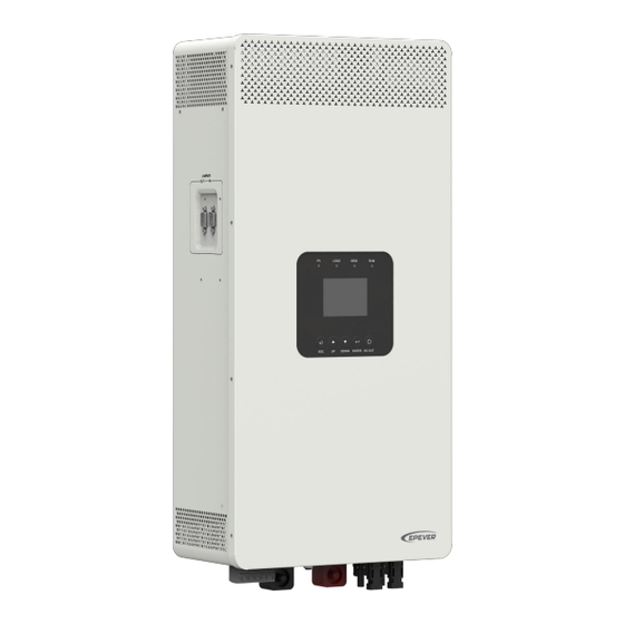
- Page 12 1.2 Appearance HP3522-AH1250P20A / HP3542-AH0650P20A / HP2022-AH0750P20A / HP2042-AH0450P20A...
- Page 13 HP2021-AH0725P20A / HP3521-AH1225P20A / HP3541-AH0625P20A/ HP2041-AH0425P20A / HP5541-AH1025P20A / HP5542-AH1050P20A...
- Page 14 RS485-A RS485-B RS485-B Please go to EPEVER official website to check or download the currently supported BMS manufacturers and the BMS parameters. (2) Dry contact specification: 1A@125VAC. Function: The dry contact interface is connected with the generator switch to turn on/off the generator.
- Page 15 Definition Definition HFS-BUS CAN-L PFS-BUS CAN-H PS-GND 6/7/8/9 Reserved 1.3 Naming rules...
- Page 16 1.4 Connection diagram No battery mode...
- Page 17 Battery mode AC loads shall be determined according to the output power of the inverter/charger. WARNING The load exceeding the maximum output power may damage the inverter/charger. For different battery types, confirm the relevant parameters before power on. ...
- Page 18 2 Interface Note: The display screen can be viewed clearly when the angle between the end-user's horizontal sight and the display screen is within 90°. If the angle exceeds 90°, the information on the display screen cannot be viewed clearly. 2.1 Indicator Indicator Status...
- Page 19 2.2 Buttons Buttons Operation Instruction Exit the current interface. Click Switch from the "home screen" to the "Main Table Data Information" screen. Browse interface: Up/Down. Click Parameters setting interface: Increase or decrease the parameter value per step size. Parameters setting interface: Increase or decrease Press and hold the parameter value per 10 times the step size.
- Page 20 2.3 Home screen Instruction Display the system time, current battery type, and charging stage. When the BMS communication is normal, the icon will be shown on the far right, while when it is ❶ abnormal, the icon will be shown on the same position. PV icon: PV connection is normal.
- Page 21 Battery voltage / battery current / lithium battery real-time SOC (Display the SOC value of the BMS when there is a BMS and the SOC value of the DSP when there is no BMS) Parallel status icon. It shows when there is two or more inverter/chargers connect in ❼...
- Page 23 2.4.2 User interface After powering on the inverter/charger, the home screen shows up. Click the "ESC" button to enter the "Main Table Data Information" screen. Click the "ENTER" button to enter the next interface, or click the "UP/DOWN" button to browse the current screen display. ...
- Page 24 password. The default parameters and setting range refer to chapter 2.5.1 Parameters list. 2.4.3 Administrator interface After powering on the inverter/charger, the home screen shows up. Press and hold the "ENTER" button to enter the password interface. Input the password correctly (0000 by default) to check all parameters or modify them.
- Page 25 Under Voltage Protect Voltage) User define: 60.0V ~(PV Under Voltage Recover Voltage minus 5V),step size: 0.1V 60.0V HP2021-AH0725P20A, HP2041-AH0425P20A HP3521-AH1225P20A, HP3541-AH0625P20A HP5541-AH1025P20A User define: 100.0V to 200.0V, or (PV Under Voltage Protect Voltage plus 5V) to 200.0V, step size: 0.1V Note: Take the maximum value between 100.0V and...
- Page 26 HP2022-AH0750P20A, HP2042-AH0450P20A, 220V HP3522-AH1250P20A, HP3542-AH0650P20A, OutputVoltLevel (Output voltage HP5542-AH1050P20A level) User define:110V, 120V HP2021-AH0725P20A, HP2041-AH0425P20A 110V HP3521-AH1225P20A, HP3541-AH0625P20A HP5541-AH1025P20A User define: 50Hz, 60Hz Note: When the Utility power is connected and the Utility frequency is detected, the output frequency will be in accordance with the Utility frequency in the Utility bypass mode.
- Page 27 OverVoltDisconect (Utility over HP5542-AH1050P20A User define:(Utility over voltage reconnect voltage voltage disconnect voltage) plus 10V)~140.0V, step size: 0.1V 140.0V HP2021-AH0725P20A, HP2041-AH0425P20A HP3521-AH1225P20A, HP3541-AH0625P20A HP5541-AH1025P20A User define: 220.0V to (Utility over voltage disconnect voltage minus 10V), step size: 0.1V 255.0V HP2022-AH0750P20A, HP2042-AH0450P20A,...
- Page 28 Namely, the maximum current at the battery end charging current) when the utility charges the battery. User define: 5.0A 70.0A HP2022-AH0750P20A and HP2021-AH0725P20A, 70.0A step size: 0.1A Namely, the maximum current at the battery end when the utility charges the battery. 100.0A User define: 5.0A...
- Page 29 HP5542-AH1050P20A and HP5541-AH1025P20A, step size: 0.1A Namely, the maximum current at the battery end when the utility charges the battery. User define: 5.0A 110.0A HP3522-AH1250P20A and HP3521-AH1225P20A, 110.0A step size: 0.1A Namely, the maximum current at the battery end when the utility charges the battery. 4.
- Page 30 Namely, the maximum allowable discharge current LimitDisChgCurrt (Battery limit discharging current) on the battery side. User define: 10.0A 220.0A HP2022-AH0750P20A and HP2021-AH0725P20A, 220.0A step size: 0.1A Namely, the maximum allowable discharge current on the battery side. User define: 10.0A 250.0A 250.0A...
- Page 31 Namely, the maximum allowable discharge current on the battery side. User define: 10.0A 380.0A HP3522-AH1250P20A and HP3521-AH1225P20A, 380.0A step size: 0.1A Namely, the maximum allowable discharge current on the battery side. Read-only, indicates abnormal ComStatus (BMS communication, indicates normal Communication Status) communication.
- Page 32 It takes effect after the “ChargeControlMode” is set as “SOC.” It takes effect after the “ChargeControlMode” is set as “SOC.” User define: 10% to 35%, or 10% to (Low energy UnderEngyAlarmSoc (Under disconnect recover Soc minus 5%), step size: 1% energy alarm Soc) Note: Take the minimum value between (Low energy disconnect recover Soc minus 5%) and...
- Page 33 temperature) When the environment or the battery temperature is lower than this value, the inverter/charger will stop discharging. BATOverTemp (Battery over User define: (Battery over temperature protect 50.0℃ recover plus 5℃) to 60℃, step size: 0.1 ℃ temperature protect) BATOverTempRecovr (Battery User define: 30 ℃...
- Page 34 User define: ALL SINGLE, ALL MULTIPLE, When two PV arrays are independently input, the value shall be set to "ALL SINGLE." When two PV arrays are connected in parallel as a single input to the inverter/charger (the PV terminals need to be paralleled externally), the value needs to be set to "ALL MULTIPLE."...
- Page 35 disconnect voltage.” After modifying the parameter and restarting the inverter/charger, the parameter will be restored to the default value (the previous modified value will not be saved). User define: OFF, ON Calibration Mode Note: This option is reserved, which is invalid currently.
- Page 36 User define: 0 to (Dry contact OFF voltage minus 44.0V (48V system) 0.1*N), step size: 0.1V. Note: N=Rated battery DryContactOnVolt (Dry contact voltage/12. ON voltage) 22.0V When the battery voltage is lower than this value, (24V system) the dry contact is connected. User define: (Dry contact ON voltage plus 0.1*N) to 50.0V (48V system)
- Page 37 User define: 1 second to 3600 seconds, step size: 1 second (Note: When setting this value, press and hold "UP/DOWN" button increase/decrease the value by 100*step size, namely, 100 seconds.) Log Data Interval 60 Sec Set the time interval of the historical data (only refers to the voltage, current and other data stored regularly, excluding the historical faults.
- Page 38 current and other data stored regularly, excluding the historical faults. Note: After pressing the ENTER button, the flashing LED light will become steady or turn off, and then the inverter/charger will restart, indicating that the reset is complete. User define: 1C, 3C This value can be obtained by viewing the battery label.
- Page 39 "ManualChageEnable" is set to "DISABLE," the lithium battery charging is not allowed. 7. Sys DataTime Setup (See chapter 2.5.5) 8. Password Setup (See chapter 2.5.6) 9. Bat Control Data Setup (This will take effect when setting the "BAT Set Mode" as "Smart.") BAT Set Mode (Battery set Smart Read-only...
- Page 40 voltage) limit voltage< Over voltage disconnect voltage, step 30.0V (24V system) size: 0.1V User define: 42.8V≤ Over voltage reconnect voltage< (Over voltage disconnect voltage minus 60.0V (48V system) 0.1*N), step size: 0.1V. Note: N=Rated battery voltage/12. OverVoltReconect (Over voltage reconnect voltage) User define: 21.4V≤...
- Page 41 disconnect voltage) disconnect voltage< Low voltage reconnect voltage, 22.2V (24V system) step size: 0.1V 42.4V DischrgeLimitVolt (Discharging (48V system) Read-only 21.2V limit voltage) (24V system) Note: Except for some parameters (such as “OutputFrequency, Phase Set, Return FactorySet, and AC Input mode” for the parallel connection etc.), the inverter/charger needs to be restarted to take effect.
- Page 42 Figure 1 “Setting process for non-lithium battery pack” When the system adopts non-lithium battery packs (such as AGM, GEL, or FLD batteries), follow the flowchart below to set parameters correctly. Set “BAT Capacity, T/C mV/℃/2, Battery Type” correctly, and set “ChargeControlMode”...
- Page 43 Figure 2 “Setting process for lithium battery pack with BMS and current control function” When the system adopts a lithium battery pack with BMS and current control function at the end of charge and discharge, and the lithium battery pack can communicate with the inverter/charger normally, follow the flowchart below to set parameters correctly.
- Page 44 Please go to EPEVER official website to download the currently supported BMS manufacturers and the BMS parameters. The inverter/charger will control charging and discharging based on the LCD settings after setting the “BMSCurent Select” as “INVALID,” or the communication between battery and inverter/charger fails.
- Page 46 The inverter/charger will control charging and discharging based on the LCD settings after setting the “BMSCurent Select” as “INVALID.” Due to the different charging and discharging characteristics and voltage consistency of lithium batteries from different manufacturers, it is necessary for professionals to guide the use of VIRTUAL_BMS for charging and discharging.
- Page 47 The inverter/charger will control charging and discharging based on the LCD settings after setting the “BMSCurent Select” as “INVALID.” Due to the different charging and discharging characteristics and voltage consistency of lithium batteries from different manufacturers, it is necessary for professionals to guide the use of VIRTUAL_BMS for charging and discharging.
- Page 48 2.5.3 Battery voltage control parameters (Smart) After setting the "BAT Set Mode" as "Smart," the battery voltage control parameters are determined by the battery type and cannot be modified. To modify them, set the "BAT Set Mode" as "Expert" first. 2.5.4 Battery voltage control parameters (Expert) After setting the "BAT Set Mode"...
- Page 49 44.4V 44.4V 44.4V 42.8-64V Low Voltage Disconnect Voltage 42.4V 42.4V 42.4V Read-only Discharging Limit Voltage The following rules must be obeyed when setting the Lead-acid battery voltage control parameters. A. Over Voltage Disconnect Voltage > Charging Limit Voltage ≥ Equalize Charging Voltage ≥ Boost Charging Voltage ≥...
- Page 50 Low Voltage Reconnect Voltage 48.7V 52.0V 42.8-64V Under Voltage Warning Recover Voltage 48.0V 51.2V 42.8-64V Under Voltage Warning Voltage 46.5V 49.6V 42.8-64V Low Voltage Disconnect Voltage 43.5V 46.4V 42.8-64V Discharging Limit Voltage 41.2V 44.0V Read-only Battery Type LNCM LNCM6S LNCM7S User Define Voltage control parameters Over Voltage Disconnect Voltage...
- Page 51 When setting the Lithium battery voltage control parameters, the following rules must be obeyed. Over Voltage Disconnect Voltage < Over Charging Protection Voltage (BMS Circuit Protection Modules)-0.2V Over Voltage Disconnect Voltage > Charging Limit Voltage ≥ Equalize Charging Voltage ≥ Boost Charging Voltage ≥...
- Page 52 2.5.6 Password modifying Enter the "Set Data Navigation" interface according to chapter 2.4.3 Administrator interface. Then click the "UP/DOWN" button to select "8 PassWord Setup", and click the "ENTER" button to enter the password modifying interface. Click the "ENTER" button to move right, click the "AC OUT"...
- Page 53 3 Single Installation 3.1 Attention Please read the manual carefully to familiarize yourself with the installation steps. Be very careful when installing the batteries, especially flooded lead-acid batteries. Please wear eye protection, and have fresh water available to rinse if contact with battery acid. ...
- Page 54 2P—25A (with arc extinguishing function) When two PV arrays are connected independently, the wire and circuit breaker size of each PV array are as follows: Model PV wire size Circuit breaker HP2021-AH0725P20A 3.1 mm /12AWG 2P—16A(with arc extinguishing function) HP2041-AH0425P20A HP5542-AH1050P20A /10AWG 2P—25A (with arc extinguishing function)
- Page 55 When two PV arrays are connected in parallel, the wire and circuit breaker size are as follows: Model PV wire size Circuit breaker HP2021-AH0725P20A /11AWG 2P—25A(with arc extinguishing function) HP2041-AH0425P20A HP5542-AH1050P20A 10mm /7AWG 2P—50A (with arc extinguishing function) HP3521-AH1225P20A 13mm /6AWG 2P—50A(with arc extinguishing function)
- Page 56 Recommended load wire size Model Load wire size Circuit breaker HP2022-AH0750P20A 3.1 mm /12AWG 2P—16A HP2042-AH0450P20A HP3522-AH1250P20A HP3542-AH0650P20A /10AWG 2P—32A HP2021-AH0725P20A HP2041-AH0425P20A HP5542-AH1050P20A /9AWG 2P—40A HP3521-AH1225P20A /8AWG 2P—50A HP3541-AH0625P20A HP5541-AH1225P20A 13mm /6AWG 2P—80A The wire size is only for reference. Suppose a long distance exists between the PV array, the inverter/charger, and the battery.
- Page 57 Step1: Determine the installation location and heat-dissipation space. The inverter/charger requires at least 30cm of clearance right and left, and 50cm of clearance above and below. Step2: According to the installation position marked with the mounting plate 1, drill two M10 holes with an electric drill.
- Page 58 3.4 Wiring the inverter/charger Connect the inverter/charger in the order of “❶Ground > ❷Battery > ❸Load > ❹PV > or Generator > ❻Optional accessories”, and disconnect the inverter/charger in the reverse ❺Utility order. The following wiring sequence is illustrated in the appearance of "HP5542-AH1050P20A." For wiring positions of other models, please refer to the actual product appearance.
- Page 59 No battery mode...
- Page 60 Battery mode The cable length of the battery should not exceed 3 meters. The recommended cable length of the PV array should not exceed 3 meters (Note: If the cable length of the PV array is less than 3 meters, the system CAUTION meets EN/IEC61000-6-3 requirements.
- Page 61 Grounding The inverter/charger has a dedicated grounding terminal, which must be grounded reliably. The grounding wire size must be consistent with the recommended load wire size. The grounding connection point shall be as close as possible to the inverter/charger, and the total grounding wire shall be as short as possible.
- Page 62 Connect the battery Please disconnect the circuit breaker before wiring and ensure that the leads of the "+" and "-" poles are polarity correctly. A circuit breaker must be installed on the battery side. For selection, please refer CAUTION to chapter 2.2 Wire and breaker size.
- Page 63 Connect the PV modules Risk of electric shock! The PV array can generate dangerous high-voltage! Disconnect the circuit breaker before wiring, and ensure that the leads of "+" and "-" poles are connected correctly. WARNING It is forbidden to connect the positive and negative poles of the PV with the ground; otherwise, the inverter/charger will be damaged.
- Page 64 Connect the Utility or generator Risk of electric shock! The Utility input can generate dangerous high-voltage! Disconnect the circuit breaker or fast-acting fuse before wiring, and ensure that the poles' leads are connected correctly. After the Utility is connected, the PV and battery cannot be grounded. In contrast, WARNING the inverter/charger cover must be grounded reliably (to shield the outside electromagnetic interference effectively and prevent the cover from causing...
- Page 65 Dry contact interface: Function: The dry contact interface can turn on/off the generator and is connected parallel with the generator's switch. Working principle: When the battery voltage reaches the Dry Contact ON Voltage, the dry contact is connected. Its coil is energized.
- Page 66 Connect optional accessories Connect the communication module Connect the WiFi module, Bluetooth module, TCP module, or 4G module to the RS485 com. port. End-users can remote monitor the inverter/charger or modify related parameters on the phone APP. Detailed setting methods, refer to the cloud APP, WiFi, Bluetooth, TCP, or 4G module user manual. Note: For the specific communication modules supported, please refer to the accessories list file.
- Page 67 Power switch Connect the battery circuit breaker first. After the inverter/charger normally works, connect the PV array and utility circuit breakers later. Otherwise, we won't assume any responsibility for not following the operation. The AC output is ON by default after the inverter/charger is powered. Before WARNING turning on the power switch, ensure the AC output is connected to loads correctly, and no safety hazard exists.
- Page 68 4 Working modes 4.1 Abbreviation Abbreviation Instruction PV power Load power LOAD Battery voltage Low Voltage Disconnect Voltage Low Voltage Reconnect Voltage Low Energy Disconnect SOC Low Energy Disconnect Recover SOC Auxiliary module OFF voltage (namely, Utility charging OFF voltage) Auxiliary module ON voltage (namely, Utility charging ON voltage) Utility Charging OFF SOC Utility Charging ON SOC...
- Page 69 ❷Any of the following is satisfied, the battery stops supplying the load. The battery voltage is lower than or equal to the LVD value. The battery SOC is lower than or equal to the LED value. Set the "Charge Control Mode" as "VOLT," the working mode is determined by the battery voltage value.
- Page 70 Note: When the battery voltage is greater than or equal to the LVR value, or the battery SOC is greater than or equal to the LER value, the working mode returns to state ❷ 4.2.3 Scenario C: Both PV and Utility are available. Discharging Mode: "PV>BP>BT"...
- Page 71 Charging Mode: "Solar" Discharging Mode: "BP>PV>BT" (C-2) The Utility supplies power to the load, and the PV charges the battery. Utility Discharging Mode: "PV>BP>BT" Charging Mode: "Solar prior" "PV>BT>BP" ❶ When the PV power is greater than the load power, the PV charges the battery and supplies extra power to the load.
- Page 72 Charging Mode: "Solar prior" Discharging Mode: "BP>PV>BT" ❶ When the PV power is greater than the (MCC*V ), the Utility and PV supply power to the load, and the PV charges the battery at the same time. > MCC*V ≤ MCC*V ❷...
- Page 73 ❷ When the PV power is lower than or equal to the (MCC*V ), the Utility and PV charge the battery, and the Utility supplies power to the load. Discharging Mode: No impact under any Charging Mode: "Utltyprior" mode (C-6) ...
- Page 74 Charging Mode: "Solar prior" Discharging Mode: "PV>BT>BP" ❶Any of the following is satisfied, the battery supplies the load. The battery voltage is higher than or equal to the AOF value. The battery SOC is greater than or equal to (D-3)...
- Page 75 Charging Mode: "Utly & solr" Discharging Mode: No impact under any mode or "Utltyprior" (D-5) The Utility supplies power to the load and charges Utility the battery simultaneously. 4.3 No battery mode Note: Under the no battery mode, the "Charging Mode" and "Discharging Mode" settings will not take effect.
- Page 76 5 Protections Protections Instruction When the PV array's actual charging current/power exceeds its rated current/power, it will charge the battery as per the rated current/power. When the PV voltage exceeds the bus voltage, the PV input power is constrained PV limit Current/Power by the load power, charging power, the power that the solar panels can deliver, and the current of the PV circuit breaker.
- Page 77 The inverter/charger will resume charging/discharging when the internal temperature is normal and the protection time lasts more than 20 minutes. HP2022-AH0750P20A 2060W≤P˂2600W 2600W≤P˂3000W 3000W≤P˂4000W P≥4000W HP2021-AH0725P20A Protect after 30 seconds Protect after 10 seconds Protect after 5 seconds Protect immediately HP2042-AH0450P20A HP2041-AH0425P20A Note: The output is recovered automatically after a delay time of 5s, 10s, and 15s separately.
- Page 78 Protections Instruction HP2022-AH0750P20A 2200W≤P˂2740W 2740W≤P˂3140W 3140W≤P˂4000W P≥4000W HP2021-AH0725P20A Protect after 30 seconds Protect after 10 seconds Protect after 5 seconds Protect immediately HP2042-AH0450P20A HP2041-AH0425P20A Note: The output is recovered automatically after a delay time of 5s, 10s, and 15s separately. The Utility bypass overload inverter/charger stops working after the 4th protection and can resume working after resetting or restarting.
- Page 79 (no-Battery mode) HP3522-AH1250P20A 5350W≤P˂6295W 6295W≤P˂6995W 6995W≤P˂8500W P≥8500W HP3521-AH1225P20A Protect after 30 seconds Protect after 10 seconds Protect after 5 seconds Protect immediately HP3542-AH0650P20A HP3541-AH0625P20A Note: The output is recovered automatically after a delay time of 5s, 10s, and 15s separately. The Utility bypass overload inverter/charger stops working after the 4th protection and can resume working after resetting or restarting.
- Page 80 6 Troubleshooting After the inverter/charger is powered on, the meter displays the boot screen all the time (unable to enter the home screen) and the red "RUN" indicator flashes. It means the communication with the inverter/charger is error. When the above fault occurs, check whether the CAUTION communication cable is disconnected.
- Page 81 Error Fault/Status Indicator Buzzer Solution code ① Check that the battery actual charging and discharging current does not BAT OCP (Battery over Err37 exceed the setting values of "Battery Max. charging current " and current protection) "Battery limit discharging current." BAT DROP (Battery Check whether the battery connection is normal, and whether the BMS Err39...
- Page 82 6.2 PV faults Error ② Fault/Status Indicator Buzzer Solution code ① PV1 OVP (PV1 over Intermittent Check if the PV open-circuit voltage is too high (greater than 500 V). Err15 indicator voltage protection) beeps The alarm is released when the PV open-circuit voltage is below 490 V. red on Turn off the inverter/charger first, wait for 5 minutes and then turn on PV1 OCP (PV1 over...
- Page 83 ②Set the "BuzzerAlert" as "ON," the buzzer will sound when a fault occurs. After the fault is eliminated, the buzzer will automatically mute. If the "BuzzerAlert" is set as "OFF," even if a fault occurs, the buzzer will not sound. 6.3 Inverter faults Error ②...
- Page 84 Error ② Fault/Status Indicator Buzzer Solution code ① INV CURR OFFSET ERR Disconnect the load completely and turn off the inverter/charger. Wait (Inverter current offset Err35 5 minutes and then turn on the inverter/charger to check if it resumes error) normal.
- Page 85 6.4 Utility faults Error ② Fault/Status Indicator Buzzer Solution code ① Check if the utility voltage exceeds the "Utility Over Voltage Disconnect GRID AC OVP (AC over voltage Intermittent Voltage," then disconnect the AC input and turn off the inverter/charger. Err8 indicator protection)
- Page 86 ①The fault/status code is displayed in the "Status" column at the bottom right corner of the LCD. When multiple faults occur simultaneously, the LCD only displays the fault code with the smallest value. ②Set the "BuzzerAlert" as "ON," the buzzer will sound when a fault occurs. After the fault is eliminated, the buzzer will automatically mute. If the "BuzzerAlert"...
- Page 87 6.6 Other faults for single inverter/charger Error Fault/Status Indicator Buzzer Solution code ① BUS OVP (DC bus over Err0 Turn off the inverter/charger. Wait 5 minutes and then turn on the voltage protection) inverter/charger to check if it resumes normal. If it is still abnormal, BUS UVP (DC bus under Err6 please contact our technical support.
- Page 88 Error Fault/Status Indicator Buzzer Solution code ① LIMITCHG (Low temperature limit Err46 charging) Check whether the ambient temperature is lower than the set "Charge low temperature limit" and "Discharge low temperature limit." LIMITDISCHG (Low temperature limit Err47 discharging) Turn off the inverter/charger. Wait 5 minutes and then turn on the EEP ERR (EEPROM Err54 inverter/charger to check if it resumes normal.
- Page 89 7 Maintenance The following inspections and maintenance tasks are recommended at least twice yearly for best performance. Make sure no block on airflow around the inverter/charger. Clear up dirt and fragments on the radiator. Check all the wired cables to ensure insulation is not damaged for serious solarization, frictional wear, dryness, insects or rats, etc.
- Page 90 8 Specifications Model HP2022-AH0750P20A HP3522-AH1250P20A Utility input 176VAC to 264VAC (Default) Utility Voltage 90VAC to 280VAC (Configurable) Utility Frequency 45Hz to 65Hz Maximum Utility Charging 110A Current Switch Response Time – Inverter to Utility: 10ms Switch Response Time Switch Response Time – Utility to Inverter (when the load power is higher than 100W): 20ms Inverter output Inverter Rated Power (@30℃)
- Page 91 Others <1.1 A <1.2A No-load Losses Test condition: Utility, PV and Load are not connected, AC output is ON, fan stops, @24V input <0.9A <0.9A Standby Current Test condition: Utility, PV and Load are not connected, AC output is OFF, fan stops, @24V input -20℃...
- Page 92 Maximum Load Efficiency Maximum Inverter Efficiency Parallel Function Yes, 12 units in standard, 16 units at most Solar controller Maximum Open-circuit 500V (At minimum operating environment temperature) Voltage 440V (At 25℃) MPPT Voltage Range 85V to 400V PV Maximum Input Power 4000W 6000W MPPT Input Channels...
- Page 93 Model HP2042-AH0450P20A Utility input 176VAC to 264VAC (Default) Utility Voltage 90VAC to 280VAC (Configurable) Utility Frequency 45Hz to 65Hz Maximum Utility Charging Current Switch Response Time – Inverter to Utility: 10ms Switch Response Time Switch Response Time – Utility to Inverter (when the load power is higher than 100W): 20ms Inverter output Inverter Rated Power (@30℃)
- Page 94 629mm × 291.4mm × 163mm Height) Mounting size (Length x Width) 592mm x 200mm Mounting hole size Φ9mm/Φ10mm Net Weight 13.3 Kg Model HP2021-AH0725P20A HP3521-AH1225P20A Utility input Utility Voltage 80VAC to 140VAC (Default) Utility Frequency 45Hz to 65Hz Maximum Utility...
- Page 95 Solar controller Maximum Open-circuit 250V (At minimum operating environment temperature) Voltage 220V (At 25℃) MPPT Voltage Range 65V to 200V PV Maximum Input Power 3000W 4000W MPPT Input Channels Two ways PV Maximum Input Current Two ways, 2x10A Two ways, 2x20A PV Maximum Short-circuit Two ways, 2x12A Two ways, 2x22A...
- Page 96 Maximum Utility Charging 100A Current Switch Response Time – Inverter to Utility: 10ms Switch Response Time Switch Response Time – Utility to Inverter (when the load power is higher than 100W): 20ms Inverter output Inverter Rated Power (@30℃) 3500W 5500W 3-second Transient Surge Output 7000W 8500W...
- Page 97 -20℃ to +50℃ (When the environment temperature exceeds Work Temperature Range 30℃, the actual output power is reduced appropriately) Storage Temperature Range -25℃ to +60℃ Enclosure IP20 Relative Humidity < 95% (N.C.) <4000M (If the altitude exceeds 2000 meters, the actual output Altitude power is reduced appropriately) Mechanical parameters...
- Page 98 MPPT Input Channels Two ways PV Maximum Input Current Two ways, 2×10A PV Maximum Short-circuit Two ways, 2×12A Current PV Maximum Charging Current MPPT Maximum efficiency ≥99.5% Battery Battery Rated Voltage 48VDC Battery Work Voltage Range 43.2VDC to 60.0VDC Battery Maximum Charging Current...
- Page 99 9 Dimensions Model:HP2021-AH0725P20A / HP2041-AH0425P20A Unit:mm...
- Page 100 Model: HP3521-AH1225P20A / HP3541-AH0625P20A- Unit:mm...
- Page 101 Model: HP3522-AH1250P20A Unit: mm...
- Page 102 Model: HHP3542-AH0650P20A / HP2042-AH0450P20A / HP2022-AH0750P20A Unit:mm...
- Page 103 Model: HP5542-AH1050P20A Unit: mm...
- Page 104 Model: HP5541-AH1025P20A Unit: mm Any changes without prior notice! Version number: V1.2...
- Page 105 SolarV GmbH Tel: +4961969076877 E-mail: info@solarv.de Website: www.solarv.de...
Need help?
Do you have a question about the HP2021-AH0725P20A and is the answer not in the manual?
Questions and answers