Table of Contents
Advertisement
Advertisement
Table of Contents

Related Manuals for Epever HP3542-AH0650P20SA


Summary of Contents for Epever HP3542-AH0650P20SA
- Page 1 Inverter/charger User Manual HP3542-AH0650P20SA HP5542-AH1050P20SA...
-
Page 3: Table Of Contents
Contents Important Safety Instructions Disclaimers 1 General Information 1.1 Overview 1.2 Appearance 1.3 Naming rules 1.4 Connection diagram 2 Interface 2.1 Indicator 2.2 Buttons 2.3 Home screen 2.4 Interface 2.4.1 Real-time data interface 2.4.2 User interface 2.4.3 Administrator interface 2.5 Parameters setting 2.5.1 Parameters list 2.5.2 Battery voltage control parameters (Smart) 2.5.3 Battery voltage control parameters (Expert) - Page 4 3.3 Mounting the inverter/charger 3.4 Wiring the inverter/charger 3.5 Operate the inverter/charger 4 Parallel Installation 4.1 Wire and breaker size for parallel operation 4.2 Precautions for parallel installation 4.3 Parallel Operation in Single phase 4.3.1 Single phase parallel wiring diagram 4.3.2 Debug for single phase parallel 4.4 Parallel Operation in Three Phase 4.4.1 Three phase parallel wiring diagram...
- Page 5 7 Troubleshooting 7.1 Battery faults 7.2 PV faults 7.3 Inverter faults 7.4 Utility faults 7.5 Load faults 7.6 Other faults for single inverter/charger 7.7 Parallel faults 7.8 BMS faults 8 Maintenance 9 Specifications 10 Dimensions...
-
Page 6: Important Safety Instructions
Important Safety Instructions Please reserve this manual for future review. This manual contains all the safety, installation, and operation instructions for the HP-AHP20SA series inverter/charger ("inverter/charger" referred to as this manual). 1. Explanation of symbols To enable users to use the product efficiently and ensure personal and property safety, please read the related words carefully when you encounter the following symbols in the manual. - Page 7 4. Safety cautions before installation When receiving the inverter/charger, please check if there is any damage in transportation. If you find any problem, please contact the transportation company or CAUTION our company in time. When installing or moving the inverter/charger, follow the instructions in the manual.
- Page 8 Both the utility input and AC output are of high voltage, do not touch the wiring connection to avoid electric shock. 7. Safety cautions for inverter/charger operation When the inverter/charger works, the shell will generate much heat, and the WARNING temperature is very high.
- Page 9 When conducting the electrical connection and maintenance, post a temporary warning sign or put up barriers to prevent unrelated personnel from entering the electrical connection or maintenance area. Improper maintenance of the inverter/charger may cause personal injury or equipment damage; ...
-
Page 10: Disclaimers
Disclaimers The warranty does not apply to the following conditions: Damage caused by improper use or inappropriate environment (it is forbidden to install the inverter/charger in humid, salt spray, corrosion, greasy, flammable, explosive, dust accumulative, or other severe environments). The actual current/voltage/power exceeds the limit value of the inverter/charger. -
Page 11: General Information
1 General Information 1.1 Overview HP-AHP20SA series, upgraded hybrid inverter/chargers that support utility charging, oil generator charging, solar charging, utility output, inverter output, and energy management. It supports parallel operation for multiple units (6 units in standard application, and support up to 16 units in parallel) in single phase and three phase, with 220VAC single phase or 380VAC three phase AC output. - Page 12 Large size LCD display for better status monitoring. RS485 communication interface with optional 4G, WiFi, or TCP modules for remote monitoring. Built-in Bluetooth to adjust settings through EPEVER APP. Three-stage charging method to ensure battery safety.
-
Page 13: Appearance
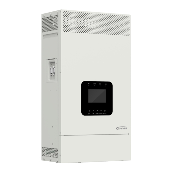
1.2 Appearance HP3542-AH0650P20SA ... - Page 14 HP5542-AH1050P20SA ...
- Page 15 BMS protocol. In addition, it realizes the communication between the inverter/charger and the BMS. Please go to EPEVER official website to download the currently supported BMS manufacturers and the BMS parameters. CAUTION (2) Dry contact specification: 1A@125VAC.
-
Page 16: Naming Rules
1.3 Naming rules 1.4 Connection diagram No battery mode ... - Page 17 Battery mode AC loads shall be determined according to the output power of the inverter/charger. WARNING The load exceeding the maximum output power may damage the inverter/charger. For different battery types, confirm the relevant parameters before power on. ...
-
Page 18: Interface
2 Interface Note: The display screen can be viewed clearly when the angle between the end-user's horizontal sight and the display screen is within 90°. If the angle exceeds 90°, the information on the display screen cannot be viewed clearly. 2.1 Indicator Indicator Status... -
Page 19: Buttons
2.2 Buttons Buttons Operation Instruction Exit the current interface. Click Switch from the "home screen" to the "Main Table Data Information" screen. Browse interface: Up/Down. Click Parameters setting interface: Increase or decrease the parameter value per step size. Parameters setting interface: Increase or decrease Press and hold the parameter value per 10 times the step size. -
Page 20: Home Screen
2.3 Home screen Instruction ❶ Display the system time, current battery type, and charging stage. means a parameter has been modified. When the BMS communication is normal, the BMS is shown on the far right. ❷ PV icon: PV connection is normal. No PV connection (or at night). -
Page 21: Interface
battery) ❼ Parallel status icon. It shows when there is two or more inverter/chargers connect in parallel successfully, and it will not display on the single inverter/charger. ★ When the PV array charges the battery, the equalizing charging is performed on the 28th of each month by default (the date can be modified). -
Page 23: User Interface
2.4.2 User interface After powering on the inverter/charger, the home screen shows up. Click the "ESC" button to enter the "Main Table Data Information" screen. Click the "ENTER" button to enter the next interface, or click the "UP/DOWN" button to browse the current screen display. "User Data Setup"... -
Page 24: Administrator Interface
password. The default parameters and setting range refer to chapter 2.4.3 Parameters list. 2.4.3 Administrator interface After powering on the inverter/charger, the home screen shows up. Press and hold the "ENTER" button to enter the password interface. Input the password correctly (0000 by default) to check all parameters or modify them. -
Page 25: Parameters Setting
2.5 Parameters setting 2.5.1 Parameters list Enter the "Set Data Navigation" interface according to chapter 2.4.3 Administrator interface. Then click the "UP/DOWN" button to select navigation 1~9 for detail settings. Default parameters and setting ranges are shown in the following table. Note: On the parameter setting interface, click the "UP/DOWN"... - Page 26 Namely, the maximum current at the battery end when the utility charges the battery. 60.0A User define: 5.0~60.0A, step size: 0.1A MaxCharge Current (Max. Utility (HP3542-AH0650P20SA) charging current) User define: 5.0~100.0A, step size: 0.1A 100.0A (HP5542-AH1050P20SA) 4. Battery Data Setup BAT Set Mode (Battery set User define: Smart (Refer to chapter 2.4.4), Expert...
- Page 27 Namely, the maximum allowable charge current on 60.0A the battery side. User define: 5.0~60.0A, step size: MaxCharginCurrent (Battery 0.1A (HP3542-AH0650P20SA) Max. charging current) User define: 5.0~100.0A, step size: 0.1A 100.0A (HP5542-AH1050P20SA) Namely, the maximum allowable discharge current on the battery side.
- Page 28 Parameters Default User define User define: VOLT, SOC VOLT: The battery voltage control parameters take effect after setting this value as “VOLT.” SOC: The SOC parameters take effect after setting ChargeControlMode (Battery VOLT this value as “SOC.” charge control mode) (Voltage) Note: If "SOC"...
- Page 29 Parameters Default User define It takes effect after the “ChargeControlMode” is set UtiltyChargeOfSoc (Utility as “SOC.” charging off Soc) User define: (Utility charging on Soc)~100%, step size: 1% SOC BAT Capacity (SOC battery User define: 0~100%, step size: 1% capacity) When the environment or the battery temperature is lower than this value, the inverter/charger will stop LimitChgTemp...
- Page 30 Parameters Default User define User define: PV>BP>BT (namely, PV>Bypass> Battery), PV>BT>BP (namely, PV>Battery> Bypass), Discharging Mode PV>BP>BT BP>PV>BT (namely, Bypass>PV> Battery) Note: For detailed working modes, refer to chapter 5.2. User define: DISABLE, ENABLE (Set this value as LiProtectEnbl (Lithium battery DISABLE "ENABLE,"...
- Page 31 Parameters Default User define User define: DISABLE, ENABLE (When using a DC power to replace the PV array for power supply PVDCInputSource DISABLE testing, it is necessary to set the "PV DC Input Source" "ENABLE." Otherwise, inverter/charger cannot work properly.) ClearAccum Energy (Clear...
- Page 32 Parameters Default User define User define: INVALID, VALID (Set this value as BMS Valid/Invalid INVALID "VALID," the inverter/charger will charge or discharge the battery based on the BMS status.) User define: 0~240, step size: 1 BMS Protocol Note: Refer to the Lithium battery protocol file. BMS Com Method RS485 User define: RS485, CAN (CAN is not supported.)
- Page 33 Parameters Default User define Level Read-only 48V battery type: AGM, GEL, FLD, LFP15S, Battery Type LFP16S, LNCM13S, LNCM14S User define: (Charging limit voltage)~16* N, step OverVoltDiscnect (Over voltage 64.0V size: 0.1V disconnect voltage) Note: N=Rated battery voltage/12. ChargingLimitVolt (Charging User define: (Equalize charging voltage)~(Over 60.0V limit voltage) voltage disconnect voltage), step size: 0.1V...
-
Page 34: Battery Voltage Control Parameters (Smart)
2.5.2 Battery voltage control parameters (Smart) After setting the "BAT Set Mode" as "Smart," the battery voltage control parameters are determined by the battery type and cannot be modified. To modify them, set the "BAT Set Mode" as "Expert" first. 2.5.3 Battery voltage control parameters (Expert) After setting the "BAT Set Mode"... - Page 35 2) Lithium battery voltage control parameters Battery Type LFP15S LFP16S User Define Voltage control parameters Over Voltage Disconnect Voltage 55.5V 59.2V 43.0~64.0V Charging Limit Voltage 54.7V 58.4V 43.0~64.0V Over Voltage Reconnect Voltage 54.7V 58.4V 43.0~64.0V Equalize Charging Voltage 54.3V 58.0V 43.0~64.0V Boost Charging Voltage 54.3V...
-
Page 36: Time Setting
Boost Voltage Reconnect Voltage > Low Voltage Reconnect Voltage > Low Voltage Disconnect Voltage ≥ Discharging Limit Voltage Under Voltage Warning Recover Voltage > Under Voltage Warning Voltage ≥ Discharging Limit Voltage Low Voltage Disconnect Voltage ≥ Over Discharging Protection Voltage (BMS Circuit Protection Modules) +0.2V The BMS circuit protection module's voltage control accuracy must be at least ±0.2V. -
Page 37: Single Installation
3 Single Installation 3.1 Attention Please read the manual carefully to familiarize yourself with the installation steps. Be very careful when installing the batteries, especially flooded lead-acid batteries. Please wear eye protection, and have fresh water available to rinse if contact with battery acid. ... -
Page 38: Wire And Breaker Size
PV wire size, please refer to the table below: Model PV wire size Breaker size HP3542-AH0650P20SA /11AWG 2P—16A When two PV arrays are connected independently, the wire and circuit breaker size of each PV array are... -
Page 39: Mounting The Inverter/Charger
CAUTION Recommended load wire size Model Load wire size Circuit breaker HP3542-AH0650P20SA /11AWG 2P—25A HP5542-AH1050P20SA /10AWG 2P—40A The wire size is only for reference. Suppose a long distance exists between the PV array, the inverter/charger, and the battery. In that case, larger wires shall be used to reduce the voltage drop and improve the system's performance. -
Page 40: Wiring The Inverter/Charger
Step2: According to the installation position marked with the mounting plate 1, drill two M10 holes with an electric drill. Step3: Insert the screws of the M8 bolts and the steel pipes into the two M10 holes. Step4: Install the inverter/charger and determine the installation position of the M10 hole (located at the bottom of the inverter/charge). - Page 41 No battery mode ...
- Page 42 Battery mode Grounding The inverter/charger has a dedicated grounding terminal, which must be grounded reliably. The grounding wire size must be consistent with the recommended load wire size. The grounding connection point shall be as close as possible to the inverter/charger, and the total grounding wire shall be as short as possible.
- Page 43 The cabinet of the inverter/charger is connected to earth through the earth Grounding rail, along with the AC input and output's PE (Protective Earth) terminal. Connect the battery Please disconnect the circuit breaker before wiring and ensure that the leads of the "+"...
- Page 44 Connect the AC load Risk of electric shock! When wiring the AC load, please disconnect the circuit breaker and ensure that the poles' leads are connected correctly. The AC loads shall be determined by the continuous output power of the inverter/charger.
- Page 45 Connect the PV modules Risk of electric shock! The PV array can generate dangerous high-voltage! Disconnect the circuit breaker before wiring, and ensure that the leads of "+" and "-" poles are connected correctly. WARNING It is forbidden to connect the positive and negative poles of the PV with the ground; otherwise, the inverter/charger will be damaged.
- Page 46 Connect the Utility or generator Risk of electric shock! The Utility input can generate dangerous high-voltage! Disconnect the circuit breaker or fast-acting fuse before wiring, and ensure that the poles' leads are connected correctly. After the Utility is connected, the PV and battery cannot be grounded. In contrast, WARNING the inverter/charger cover must be grounded reliably (to shield the outside electromagnetic interference effectively and prevent the cover from causing...
- Page 47 Dry contact interface: Function: The dry contact interface can turn on/off the generator and is connected parallel with the generator's switch. Working principle: When the battery voltage reaches the Dry Contact ON Voltage, the dry contact is connected. Its coil is energized.
-
Page 48: Operate The Inverter/Charger
Connect optional accessories Connect the communication module Connect the WiFi module, 4G module, or TCP module to the RS485 com. port. End-users can remote monitor the inverter/charger or modify related parameters on the phone APP. Detailed setting methods, refer to the WiFi/4G/TCP module user manual. Note: When connecting the WiFi module or 4G module, an additional communicable cable is needed. - Page 49 Power switch Connect the battery circuit breaker first. After the inverter/charger normally works, connect the PV array and utility circuit breakers later. Otherwise, we won't assume any responsibility for not following the operation. The AC output is ON by default after the inverter/charger is powered. Before WARNING turning on the power switch, ensure the AC output is connected to loads correctly, and no safety hazard exists.
-
Page 50: Parallel Installation
4.1 Wire and breaker size for parallel operation Recommended battery wire and breaker size when connecting a single inverter charger. Model Battery wire size Breaker size HP3542-AH0650P20SA 20mm2/4AWG 2P—125A HP5542-AH1050P20SA 35 mm2/2AWG 2P—200A You need to connect the battery cables of each inverter/charger together. Use a connector or bus-bar as a joint to connect the battery cables together, and then connect to the battery terminals. - Page 51 Wiring: Before wiring, please remove the wire cover by unscrewing the three screws.
-
Page 52: Parallel Operation In Single Phase
At the inverter/charger’s utility and load terminal plate, from left to right, are GRID_L, GRID_N, LOAD_N, LOAD_L. Please wire correctly according to the silk print on the WARNING terminals, DO NOT connect it backwards! Be sure the length of battery cables to each inverter/charger is the same. Otherwise, there will be voltage difference between inverter/charger and battery, to cause parallel WARNING inverter/chargers not working. - Page 53 Three inverter chargers in single phase parallel Connect the battery, utility and load Connect the parallel communication cables Four inverter chargers in single phase parallel Connect the battery, utility and load ...
- Page 54 Connect the parallel communication cables Five inverter chargers in single phase parallel Connect the battery, utility and load Connect the parallel communication cables ...
-
Page 55: Debug For Single Phase Parallel
Six inverter chargers in single phase parallel Connect the battery, utility and load Connect the parallel communication cables Connect PV PV connection refers to chapter 3. Single Installation>Wiring the inverter charger>Connect the PV modules. Each inverter charger should be connected to PV modules separately, and it is prohibited to connect the same PV modules to two or more inverter chargers. - Page 56 reverse connect. Ensure that the strong and the weak current wiring is not crossed to prevent interference with the parallel communication line. That is, the parallel communication line does not cross with PV, battery input line and AC output line wiring, otherwise the parallel communication line may be interfered and an Err87 fault will alarms (synchronization signal reception failure).
- Page 57 screen of the set equipment is successful. Only after the phase settings of all parallel equipment are successful can the output circuit breaker can be connected. WARNING Step 3: Turn on each inverter/charger, the parallel status icon will display. See the example of single phase parallel operation of 6 units as below.
-
Page 58: Parallel Operation In Three Phase
(parallel AC input source abnormal). When connecting the utility for bypass charging, if only the utility breaker of a certain inverter charger is disconnect, be careful that the utility input terminals of this inverter WARNING charger still have power. Step 5: If there is no fault alarm, indicates the parallel system is completely installed. Step 6: Please connect all circuit breakers on the load side, and the parallel system will start to provide power to the load. - Page 59 Connect the parallel communication cables Connect the parallel communication ports (DB9 ports) on the side of each inverter/charger by the p arallel communication cables. Connect the CAN bus terminal resistor(DB9 connector), included accessory, to the parallel commu nication ports(DB9 ports) of the first and last inverter/charger. Two for Phase A, one for Phase B, and one for Phase C Connect the battery, utility and load ...
- Page 60 Connect the parallel communication cables Two for Phase A, two for Phase B, and one for Phase C Connect the battery, utility and load Connect the parallel communication cables ...
- Page 61 Three for Phase A, one for Phase B, and one for Phase C Connect the battery, utility and load Connect the parallel communication cables Two for Phase A, two for Phase B, and two for Phase C Connect the battery, utility and load ...
- Page 62 Connect the parallel communication cables Three for Phase A, two for Phase B, and one for Phase C Connect the battery, utility and load Connect the parallel communication cables ...
- Page 63 Four for Phase A, one for Phase B, and one for Phase C Connect the battery, utility and load Connect the parallel communication cables Connect PV PV connection refers to chapter 3. Single Installation > Wiring the inverter charger > Connect the PV modules.
-
Page 64: Debug For Three Phase Parallel
4.4.2 Debug for three phase parallel Step 1: Double check the parallel wiring according to the following requirements before debugging: Ensure that the wires are connected correctly according to the wiring diagram, and do not reverse connect. Ensure that the strong and the weak current wiring is not crossed to prevent interference ... - Page 65 Parallel parameters setting for Phase B After three phase wiring is completed, the “Phase Set” of each inverter/charger in Phase B needs to be changed to “Phase B”. See the example of screen display on the slave unit for two inverter/chargers in Phase B below.
- Page 66 After“Phase Set”is changed, must turn off the inverter/charger for 10 seconds before restarting, only then can the setting be successful. Follow the above flowchart to re-enter the “Load Data Setup” interface and check if the “Phase Set” is correct; Or CAUTION after starting at least 2 parallel equipment, observe whether the phase setting on the screen of the set equipment is successful.
- Page 67 Slave unit in Phase B: B (S)-2 Slave unit in Phase C: C (S)-2 When parallel operation in three phase, Master unit(M) only displays on the screen of one of the inverter/chargers in Phase A. The inverter/chargers in Phase B or C will not display Master(M), but only display Slave(S).
-
Page 68: Bms Connection For Parallel Equipment
Step 4: Connect all AC breakers on the utility input side of all inverter/chargers, and the utility input of all inverter/chargers must be connected to the same three-phase utility. And the input three-phase utility should match the phase setting of the inverter/chargers, so that the inverter/chargers can work normally. -
Page 69: Bms Parameter Setting For Parallel
4.5.2 BMS parameter setting for parallel Set battery type When charging and discharging the battery by BMS, it is necessary to select the correct battery type through the LCD according to the actual battery used. Operation steps are as follows:... - Page 70 Set parameters of “BMS Valid/Invalid, BMS voltage control enable, BMS Parameter Valid” After BMS connection is completed, related BMS parameters need to be set on the LCD of the connected inverter/charger, to set “BMS Valid/Invalid” as “VALID”, set “BMSVltCntrlEnable” as “ENABLE”, and set “BMS Param Valid”...
- Page 71 Step 1: Based on the manufacturer information of the lithium battery connected to the inverter/charger, determine the lithium battery conversion communication protocol number PRO (Go to EPEVER website and download the “BMS Communication Protocols & Fixed ID” file to obtain the corresponding PRO numbers for different lithium battery manufacturers).
-
Page 72: Bms Control Logic For Charging And Discharging
4.5.3 BMS control logic for charging and discharging In either single phase application or three phase application, after the BMS is correctly connected and BMS parameters are set correctly, the system will follow the following logic to control the charging and discharging of lithium battery. - Page 73 In “BMS SET VALUE” interface, click the "UP/DOWN" button to view the parameter. When multiple battery packs are connected in parallel, the “GP_ChagCurntLimit” and “GP_DichagCurntLmt” will control the GP_ChagCurntLimit① battery charging and discharging. The “GP_ChagCurntLimit” is the total charging current limit of all battery packs. Namely, the “ChgCurntLimit”...
- Page 74 available “ChgCurntLimit”, “MaxCharginCurrent” and “MaxCharge Current” Once the actual battery discharge current exceeds the Single “DischagCurntLimit” or “LimitDisChgCurrt”, LCD will display battery battery over-current error(Err37) after the inverter/charger runs for pack 1 minute, and the inverter/charger will restart after 30 seconds. discharging the inverter/charger will run for 1 minute.
-
Page 75: Parameters Sync Update Item
4.6 Parameters Sync Update Item When the parameters in the following table are set on the LCD of any inverter/charger, the parameters on the other inverter/chargers will be automatically updated. Note: The definition and setting range of the following parameters refer to chapter 2.5.1 Parameter List. -
Page 76: Working Modes
5 Working modes 5.1 Abbreviation Abbreviation Instruction PV power Load power LOAD Battery voltage Low Voltage Disconnect Voltage Low Voltage Reconnect Voltage Low Energy Disconnect SOC Low Energy Disconnect Recover SOC Auxiliary module OFF voltage (namely, Utility charging OFF voltage) Auxiliary module ON voltage (namely, Utility charging ON voltage) Utility Charging OFF SOC Utility Charging ON SOC... -
Page 77: Scenario B: Pv Is Available, But The Utility Is Not Available
❷Any of the following is satisfied, the battery stops supplying the load. The battery voltage is lower than or equal to the LVD value. The battery SOC is lower than or equal to the LED value. Set the "Charge Control Mode" as "VOLT," the working mode is determined by the battery voltage value. -
Page 78: Scenario C: Both Pv And Utility Are Available
Note: When the battery voltage is greater than or equal to the LVR value, or ❷ the battery SOC is greater than or equal to the LER value, the working mode returns to state 5.2.3 Scenario C: Both PV and Utility are available. Discharging Mode: "PV>BP>BT"... - Page 79 Charging Mode: "Solar" Discharging Mode: "BP>PV>BT" The Utility supplies power to the load, and the (C-2) PV charges the battery. Utility Discharging Mode: "PV>BP>BT" Charging Mode: "Solar prior" ❶ When the PV power is greater than the load "PV>BT>BP"...
- Page 80 Charging Mode: "Solar prior" Discharging Mode: "BP>PV>BT" ❶ When the PV power is greater than the (MCC*V ), the Utility and PV supply power to the load, and the PV charges the battery at the same time. > MCC*V ≤ MCC*V ❷...
-
Page 81: Scenario D: The Pv Is Not Available, But The Utility Is Available
❷ When the PV power is lower than or equal to the (MCC*V ), the Utility and PV charge the battery, and the Utility supplies power to the load. Discharging Mode: No impact under any Charging Mode: "Utltyprior" mode (C-6) ... - Page 82 ❶Any of the following is satisfied, the battery Charging Mode: "Solar prior" Discharging Mode: "PV>BT>BP" supplies the load. The battery voltage is higher than or equal to the AOF value. The battery SOC is greater than or equal to (D-3)...
-
Page 83: No Battery Mode
Charging Mode: "Utly & solr" Discharging Mode: No impact under any mode or "Utltyprior" (D-5) The Utility supplies power to the load and charges Utility the battery simultaneously. 5.3 No battery mode Note: Under the no battery mode, the "Charging Mode" and "Discharging Mode" settings will not take effect. -
Page 84: Protections
6 Protections Protections Instruction When the PV array's actual charging current/power exceeds its PV limit rated current/power, it will charge the battery as per the rated Current/Power current/power. When the PV is not charging and short circuit, the inverter/charger is PV short circuit not damaged. - Page 85 Protections Instruction The output is turned off immediately in the occurrence of short-circuiting. And then, the output is recovered automatically after a delay time of 5s, 10s, and 15s separately (less than three times Load output short recovery within 5 minutes, it will be recounted). The inverter/charger circuit stops working after the 4th protection and can resume working after resetting or restarting.
-
Page 86: Troubleshooting
7 Troubleshooting After the inverter/charger is powered on, the meter displays the boot screen all the time (unable to enter the home screen) and the red "RUN" indicator flashes. It means the communication with the inverter/charger is error. When the above fault occurs, check whether the CAUTION communication cable is disconnected. -
Page 87: Pv Faults
Error ① Fault/Status Indicator Buzzer Solution code Check that the battery actual charging and discharging current does not BAT OCP (Battery over Err37 exceed the setting values of "Battery Max. charging current " and current protection) "Battery limit discharging current." BAT DROP (Battery Check if the battery connection is normal and the BMS communication Err39... - Page 88 Error ① ② Fault/Status Indicator Buzzer Solution code Check if the PV open-circuit voltage is too low (lower than the set value of PV1 UVP (PV1 under “PV under voltage protect voltage”), or whether the PV capacity is Err16 voltage protection) insufficient.
-
Page 89: Inverter Faults
Error ① Fault/Status Indicator Buzzer Solution code PV1 PCTO (PV1 Err52 Turn off the inverter/charger first, wait for 5 minutes and then turn on the pre-charge timeout) indicator inverter/charger to check if it resumes normal. If it is still abnormal, please PV2 PCTO (PV2 green on contact our technical support. - Page 90 Error ① ② Fault/Status Indicator Buzzer Solution code INV OTP (Inverter over Err10 Ensure the inverter/charger is installed in a cool and well-ventilated place. temperature protection) HARD INV OVP (Inverter hardware over voltage Err22 protection) HARD INV OCP (Inverter hardware over current Err23 Disconnect the load completely and turn off the inverter/charger.
-
Page 91: Utility Faults
②Set the "BuzzerAlert" as "ON," the buzzer will sound when a fault occurs. After the fault is eliminated, the buzzer will automatically mute. If the "BuzzerAlert" is set as "OFF," even if a fault occurs, the buzzer will not sound. 7.4 Utility faults Error ①... -
Page 92: Load Faults
①The fault/status code is displayed in the "Status" column at the bottom right corner of the LCD. When multiple faults occur simultaneously, the LCD only displays the fault code with the smallest value. ②Set the "BuzzerAlert" as "ON," the buzzer will sound when a fault occurs. After the fault is eliminated, the buzzer will automatically mute. If the "BuzzerAlert"... -
Page 93: Other Faults For Single Inverter/Charger
7.6 Other faults for single inverter/charger Error ① Fault/Status Indicator Buzzer Solution code BUS OVP (DC bus over Err0 Turn off the inverter/charger. Wait 5 minutes and then turn on the voltage protection) inverter/charger to check if it resumes normal. If it is still abnormal, BUS UVP (DC bus under Err6 please contact our technical support. - Page 94 Error ① Fault/Status Indicator Buzzer Solution code LIMITCHG (Low temperature limit Err46 charging) Check whether the ambient temperature is lower than the set "Charge LIMITDISCHG (Low low temperature limit" and "Discharge low temperature limit." temperature limit Err47 discharging) Turn off the inverter/charger. Wait 5 minutes and then turn on the EEP ERR (EEPROM Err54 inverter/charger to check if it resumes normal.
-
Page 95: Parallel Faults
7.7 Parallel faults Error ② Fault/Status Indicator Buzzer Solution ① code Check if the parallel communication connection wire (DB9) and terminal CAN communication Err80 resistance are loose, and ensure that the parallel communication connection failure wires between each inverter/charger are securely connected. Please check according to the following to ensure the uniformity of the phase settings of the inverter/chargers in the parallel system: 1. - Page 96 Error ② Fault/Status Indicator Buzzer Solution ① code Check if the parallel communication connection wire(DB9) is loose, and Fail to receive sync Err87 ensure that the parallel communication wires between all inverter/chargers signal are securely connected. In parallel system, there are situations where the inverter/charger is not connected to the utility, or utility is not connected correctly, adjust the wire connection in correct sequence.
-
Page 97: Bms Faults
7.8 BMS faults Error ② Fault/Status Indicator Buzzer Solution ① code BMS ChageDisable (BMS charge disable) Err64 BMS DisChageDisable (BMS discharge disable) Err65 BMS OVP (BMS over voltage protect) Err66 BMS Chage Protect (BMS charge protect) Err67 Intermittent Check the BMS communication BMS Chage TEMP ERR (BMS charge temperature error) Err68 beeps... -
Page 98: Maintenance
8 Maintenance The following inspections and maintenance tasks are recommended at least twice yearly for best performance. Make sure no block on airflow around the inverter/charger. Clear up dirt and fragments on the radiator. Check all the wired cables to ensure insulation is not damaged for serious solarization, frictional ... -
Page 99: Specifications
9 Specifications Model HP3542-AH0650P20SA HP5542-AH1050P20SA Utility input Utility Voltage 176VAC~264VAC (Default), 90VAC~280VAC (Configurable) Utility Frequency 45Hz~65Hz Maximum Utility Charging 100A Current Switch Response Time – Inverter to Utility: 10ms Switch Response Time Switch Response Time – Utility to Inverter (when the load... - Page 100 Model HP3542-AH0650P20SA HP5542-AH1050P20SA Others <0.7A <1.0 A No-load Losses Test condition: Utility, PV and Load are not connected, AC output is ON, fan stops, @48V input <0.15A Standby Current Test condition: Utility, PV and Load are not connected, AC output is OFF, fan stops, @48V input -20℃~+50℃...
-
Page 101: Dimensions
10 Dimensions Model: HP3542-AH0650P20SA (Unit: mm) - Page 102 Model: HP5542-AH1050P20SA (Unit: mm) Any changes without prior notice! Version number: V1.0...
- Page 104 HUIZHOU EPEVER TECHNOLOGY CO., LTD. Tel: +86-752-3889706 E-mail: info@epever.com Website: www.epever.com...
Need help?
Do you have a question about the HP3542-AH0650P20SA and is the answer not in the manual?
Questions and answers