Table of Contents
Advertisement
Quick Links
Advertisement
Table of Contents

Related Manuals for Ronix 5605


Summary of Contents for Ronix 5605
- Page 1 ELECTRIC TABLE SAW 31.5cm 5605 www.ronixtools.com...
-
Page 3: Specification
SPECIFICATION 5605 Model Power 2000W Voltage 220-240V Frequency 50-60Hz No Load Speed 2950RPM Disc Diameter 315mm Tilt Range 0° To 45° Φ315×3×Φ30mm 40Z Saw Blade Size 0°: 83mm Max Cutting Capacity 45°: 50mm Main Table Size 800×550mm Pulling Extension Table 800×400mm... -
Page 4: Part List
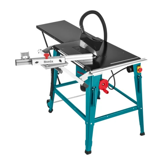
PART LIST Dust connector Extension table Blade guard Blade Ruler fence Table saw Wheel Blade height adjustment handle Base SYMBOLS The rating plate on your tool may show symbols. These represent important information about the product or instructions on its use. Wear hearing protection. -
Page 5: General Power Tool Safety Warnings
The product conforms to RoHS requirements. General warning. Waste electrical products should not be Disposed of as household waste. Please recycle where facilities exist. Check with your Local Authority or retailer for recycling advice. Do not touch the moving blade. Do not approach the machine with loose clothing. -
Page 6: Electric Safety
accidents. - Don’t operate power tools in explosive atmospheres, such as in the presence of flammable liquids, gases, or dust. Power tools create sparks which may ignite the dust or fumes. - Keep children and bystanders away while operating a power tool. Distractions can cause you to lose control. - Page 7 the influence of drugs, alcohol, or medication. A moment of inattention while operating power tools may result in serious personal injury. - Use personal protective equipment. Always wear eye protection. Protective equipment such as dust masks, non-skid safety shoes, hard hats, or hearing protection used for appropriate conditions will reduce personal injuries.
- Page 8 of starting the power tool accidentally. - Store idle power tools out of the reach of children and don’t allow persons unfamiliar with power tool or these instructions to operate the power tool. Power tools are dangerous in the hands of untrained users. - Maintain power tools.
- Page 9 guard, riving knife. The guard, riving knife help to reduce the risk of injury. - Make sure the saw blade is not contacting the guard, riving knife or the workpiece before the switch is turned on. Inadvertent contact of these items with the saw blade could cause a hazardous condition.
- Page 10 fence and the saw blade. Use a push stick when the distance between the fence and the saw blade is less than 150 mm, and use a push block when this distance is less than 50mm. work helping devices will keep your hand at a safe distance from the saw blade.
-
Page 11: Kickback Causes And Related Warnings
KICKBACK CAUSES AND RELATED WARNINGS - Never stand directly in line with the saw blade. Always position your body on the same side of the saw blade as the fence. Kickback may propel the workpiece at high velocity toward anyone standing in front and in line with the saw blade. - Page 12 sharp, and with a sufficient set. Never use warped saw blades or saw blades with cracked or broken teeth. Sharp and properly set saw blades minimize binding, stalling, and kickback. TABLE SAW OPERATING PROCEDURE WARNINGS - Turn off the table saw and disconnect the power cord when removing the table insert, changing the saw blade, or making adjustments to the riving knife or saw blade guard, and when the machine is left unattended.
-
Page 13: Intended Use
not use grinding wheels, wire brushes, or abrasive wheels on a table saw. Improper saw blade installation or use of accessories not recommended may cause serious injury. INTENDED USE - The bench-type circular saw is designed for the slitting and cross-cutting of all types of timber, commensurate with the machine’s size. -
Page 14: Installation And Assembly
- All covers and safety devices have to be properly fitted before the equipment is switched on. - It must be possible for the blade to run freely. - When working with wood that has been processed before, watch out for foreign bodies such as nails or screws, etc. - Page 15 ø ø 50px 50px ø ø 32px 6x16mm 50px ø ø ø 4x20mm 5x8mm 18px ø 6x16mm USER MANUAL...
- Page 16 1- Main body 2- Support stands x4pcs (A, B, C, D) 3- Ruler fence x1pc 4- Lateral Support x2pc shorter&2pc Longer 5- Extension tube table support x2pc shorter &2pc Longer 6- Quick locked fence 7- 1pc x shorter slide guide, 1pc x longer scale plate 8- Blade guard 9- Plastic push handle for workpiece 10- Angle Ruler ( It is assembled with the ruler fence when using )
- Page 17 STEP 1 Assemble the dust connect (Pic. a) with screw M5x8 and flat washer Ø5mm (Pic. b); make sure the 4 sets screws must be assembled totally. Please take more attention to the dust right direction. ø6 ø6 ø6 ø 6x16 STEP 2 Assemble the 4-piece support stands to the main body.
- Page 18 STEP 3 Assemble the Lateral Support x2pcs shorter &2pcs Longer. The two shorter lateral support to be assembled between support Stand A&B, C&D; The two longer lateral support to be assembled between the support Stand A&D,C&B. Use screw Ø6X16 + Ø6 spring washer+Ø6flat washer +Ø6 nut (Pic.
- Page 19 STEP 5 Assemble the switch on Support stand A Find the switch (Pic. j), and you see on stand A there is a frame, putting the switch onto the frame (Pic. k). Then, on the other side, use the Ø4x20 screws to fix the switch as (Pic.
- Page 20 STEP7 Assemble long scale plate. In the position as (Pic. n). indicates, use hexagon screw Ø6x16+Ø6 flat washers+Ø6 spring washers+Ø6 nut (Pic. o). to fix on the side of the table, TOTAL 4 set (Pic. p); then take the longer scale plate to slide as (Pic. q). arrow direction; at last, tighten the 4 sets screws as (Pic.
- Page 21 STEP 9 Assemble the two pieces of longer extension tube table support. Please find machine support stands B-C (Pic. v). then use Ø6X16 screws set (Pic. w). to fix the longer extension tube table support on the machine lateral support as (Pic. x). ø...
- Page 22 other person tightens them with 2 sets of Ø6X16 screws as (Pic. 4). In the next step, as (Pic. 5), make the two longer extension tube table support applied to the extension table, and use 2 sets of Ø6X16 screws to fix it. In order to make the extension table and main table in a straight line, the user can use a ruler or the fence to make a test, as (Pic.
-
Page 23: Blade Guard
STEP12 Assemble the blade guard and Corrugated tube. BLADE GUARD: Rotate the round shape handlebar (Pic.14) in a clockwise direction until the blade reaches to top as Pic.15. Put the blade guard together with the screw on top of the slitter (as Pic.16) so that the screw is snug in the oval hole. - Page 24 CORRUGATED TUBE: Fit one side of the corrugated tube (Pic.17) to the socket on the saw blade guard, and make the corrugated tube pass through the circle hook (as pic.10, Pic.18 ) Connect the end of the rube to connect with the dust connector adapter.
- Page 25 be adjusted angles to user’s needs. ø ø6 ø6 ø6 6x16 STEP14 Assemble the moving wheels. On support stands C&D, find the two screw holes on each stands as in Pic. 27. Then put the moving wheel close to C&D stand as in Pic. 28. Use two sets of Ø6X16 screws to fix the wheels guard and stands (Pic.
-
Page 26: Sliding Table Assembly
STEP16 Replace the blade Remove the blade guard. (take opposite operate method from Step. 12) to move away the blade guard and corrugated tube. Then, find the four screws position on the plastic insert (Pic. 32). use a tool (user needs to find a cross spanner) to loosen the four screws (Pic. - Page 27 1- Auxiliary slide rod assembly 2- Sliding angle ruler assembly 3- Auxiliary slide rod 4- Connecting bracket 2pcs 5- Locked handle 6- Carriage bolt M6×65 7- Hexagon screw M10×60 8- Countersunk head tapping screw ST4.8×12 9- Auxiliary slide rod cover 10- Hexagon screw M6×20 4pcs 11- Flat pad ø6 4pcs 12- Spring washer ø6 4pcs...
- Page 28 14- Hexagon screw M6×35 15- Self-locking nut ASSEMBLY STEP17 - Fix auxiliary slide rod cover (9) to auxiliary slide rod assembly (1) with countersunk head tapping screw ST4.8x12 (8), as (Pic.A). -In order to assembly sliding angle ruler, please fix carriage bolt M6x65(6), sliding angle ruler assembly (2), locked Handle (5) together to auxiliary slide rod assembly (1) as (Pic.B).
- Page 29 sliding rod assembly (3) as (Pic.D). Use hexagon screw M6x35(14) get through main sliding rod (3), then fix with self-locking nut (15) as (Pic.D) STEP18 - As (Pic E) shows, take off longer scale plate and shorter slide guide with reverse operation of Pic.n/o/p/q/r/s/t/u. - If longer scale plate and shorter slide guide not pre-assembled, no extra such step here.
- Page 30 STEP19 Assembly sliding table to machine. (Pic. F) Disassembly screws Ø6x16 + Ø6 flat washer+Ø6 spring washer +Ø6 nut (Pic. d) from support stands B&C, then fix sliding table with screws (Pic. d) Finished as (Pic. G) Remarks: There are 2 positions (P1 or P2) can be chosen while fix sliding table.
- Page 31 OPERATION INSTRUCTIONS WARNING! As with all power tools, there are potential hazards involved with the use of this table saw. It is, therefore, vital to ensure you read, understand, and apply all the safety instructions. Failure to do so may cause serious damage and/or personal injury and may invalidate your warranty.
- Page 32 with the cutting direction. - Switch on the saw. - Place your hands (with fingers closed) flat on the workpiece and push the workpiece along the quick lock fence and into the blade - Guide at the side with your left or right hand (depending on the position of the quick lock fence) only as far as the front edge of the saw blade guard.
- Page 33 showing, user needs to loose the two knobs first. Then hold the blade bottom guard and move it to the opposite side of the switch as in Pic.40. Until the angel ruler to be at 45°as arrow shows in Pic.41, then lock the two knobs which Pics.
- Page 34 ELECTRIC TABLE SAW...
- Page 36 www.ronix.ir...
Need help?
Do you have a question about the 5605 and is the answer not in the manual?
Questions and answers