Table of Contents
Advertisement
Quick Links
Advertisement
Table of Contents

Related Manuals for Ronix 5603


Summary of Contents for Ronix 5603
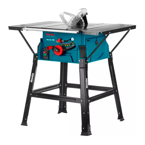
- Page 1 ELECRIC TABLE SAW 2 5cm 5603...
-
Page 3: Technical Specification
TECHNICAL SPECIFICATION 5603 Model Power 2000W Voltage 220-240V Frequency 50-60Hz No Load Speed 4800RPM Disc Diameter 250mm Tilt Range 0° To 45° φ250xφ30x2.8mm Saw Blade Size 0°: 85mm Max Cutting Capacity 45°: 53mm Main Table Size 546x630mm Pulling Extension Table... -
Page 4: Part List
PART LIST 20B 20 ELECTRIC TABLE SAW 25cm... - Page 5 1- Saw bench 2- Bench insert 3- Saw blade 4- Saw blade guard 5- Graduated ruler 6- Riving knife 7- Transverse stop 8- Bench extension 9- Push stick 10- Underframe 11- On/Off switch 12- Hand wheel 13- Locking handle 14- Guide rail 15- Rip fence 16- Legs 16A- Rubber feet...
- Page 6 Wear hearing protection. Wear eye protection. Wear respiratory protection. Conforms to relevant safety standards. Double insulated for additional protection. Read the instruction manual. Dangerous voltage. Cutting danger. Product conforms to RoHs requirements General warning. Waste electrical products should not be Disposed of with household waste.
-
Page 7: General Power Tool Safety Warnings
GENERAL POWER TOOL SAFETY WARNINGS WARNING! - Read all safety warnings and all instructions. Failure to follow the warnings and instructions may result in electric shock, fire and or serious injury. - Save all warnings and instructions for future reference. - The term “power tool”... -
Page 8: Personal Safety
of electric shock. - If operating a power tool in a damp location is unavoidable, use a residual current device RCD protected supply. Use of an RCD reduces the risk of electric shock. - Use of power supply via a RCD with a rated residual current of 30mA or less is always recommended. - Page 9 POWER TOOL USE AND CARE - Don’t force the power tool. Use the correct power tool for your application. The correct power tool will do the job better and safer at the rate for which it was designed. - Don’t use the power tool if the switch doesn’t turn it on and off. Any power tool that cannot be controlled with the switch is dangerous and must be repaired.
- Page 10 GUARDING RELATED WARNINGS - Keep guards in place. Guards must be in working order and be properly mounted. A guard that is loose, damaged, or is not functioning correctly must be repaired or replaced. - Always use saw blade guard, riving knife for every through-cutting operation.
- Page 11 blade. A moment of inattention or a slip could direct your hand towards the saw blade and result in serious personal injury. - Feed the workpiece into the saw blade or cutter only against the direction of rotation. Feeding the workpiece in the same direction that the saw blade is rotating above the table may result in the workpiece and your hand, being pulled into the saw blade.
-
Page 12: Kickback Causes And Related Warnings
- Feed workpiece at an even pace. Do not bend or twist the workpiece. If jamming occurs, turn the tool off immediately, unplug the tool then clear the jam. Jamming the saw blade by the workpiece can cause kickback or stall the motor. - Do not remove pieces of cut-off material while the saw is running. - Page 13 cause kickback. - Support large panels to minimize the risk of saw blade pinching and kickback. Large panels tend to sag under their own weight. Support(s) must be placed under all portions of the panel overhanging the table top. - Use extra caution when cutting a workpiece that is twisted, knotted, warped or does not have a straight edge to guide it with a meter gauge or along the fence.
-
Page 14: Intended Use
may self-ignite. - The table saw must be secured. A table saw that is not properly secured may move or tip over. - Remove tools, wood scraps, etc. from the table before the table saw is turned on. Distraction or a potential jam can be dangerous. - Always use saw blades with corrects size and shape (diamond versus round) of arbor holes. - Page 15 persons who use and service the machine have to be acquainted with this manual and must be informed about its potential hazards. It is also imperative to observe the accident prevention regulations in force in your area. The same applies for the general rules of occupational health and safety.
- Page 16 NOTE: If compounds with a bolt (round head/or hexagon), hex nuts and washers are backed up, the washer must be fitted under the nut. - Insert screws each from outside to inside. Secure connections with nuts on the inside. NOTE: Tighten the nuts and bolts during assembly only to the extent that they cannot fall down.
- Page 17 Screw the support struts (22) to the table extensions (8) with the hex bolts (19), spring washer (20a), and washers (20b). Subsequently, tighten all screws. MOUNTING RACK (FIGS 6 - 7) USER MANUAL...
- Page 18 Screw the four support legs (18) together with the support struts (22) onto the saw with the hex bolts (19), the spring rings (20a) and the washers (20b) (fig. 6). For this use the saw blade key (21a), part of the delivery contents (Fig.
- Page 19 CAUTION! Pull out the main plug! The setting of the riving knife (6) must be checked prior to commissioning of the riving knife must be checked prior to commissioning. Set the saw blade (3) to the max. cutting depth, bring it to the 0° position and lock it.
- Page 20 25 6 REPLACING THE BENCH INSERT (FIG 8) In case of wear or damage, the bench insert (2) must be replaced; otherwise, there is an increased risk of injury. Unfasten the bolt (23) using a Phillips screwdriver. Take out the worn bench insert (2).
- Page 21 INSTALLING/REPLACING THE SAW BLADE (FIG 13) CAUTION! Pull out the main plug and wear safety gloves. Dismount the saw blade guard (4). Remove the bench insert (2). Loosen the nut by placing a saw blade spanner (21a) on the nut while holding up another saw blade spanner (21b) on the motor shaft (see Fig.
- Page 22 CUTTING DEPTH (FIG 14) Turn the round handle (12) to set the blade (3) to the required cutting depth. - Anticlockwise: smaller cutting depth - Clockwise: larger cutting depth After each new adjustment it is advisable to carry out a trial cut in order to check the set dimensions.
- Page 23 WORKING WITH THE RIP FENCE SETTING THE STOP HEIGHT (FIGS 15 - 16) The stop rail of the rip fence (27) has two guide surfaces with different heights. Depending on the thickness of the material to be cut, the stop rail (27) as shown in Fig.
- Page 24 TURNING THE STOP RAIL (FIGS 15 - 16) Loosen the wing nuts (28) first for rotating the stop rail (27). Now, the stop rail (27) can be removed from the guide rail (29) and pushed over it again using the corresponding guide. Tighten the wing nuts (28) again.
-
Page 25: Operation
the eccentric lever for the rip fence (30). TRANSVERSE STOP (FIG 18) Push the transverse stop into a groove (31) of the saw bench. Loosen the handle screw (32). Turn the cross stop (7) until the desired angle is set. The arrow on the transverse stop is at the set angle. - Page 26 reach its maximum speed of rotation before commencing with the cut. Secure long workpieces against falling off at the end of the cut (e.g. with a roller stand etc.) Take extra care when starting the cut! Never use the equipment without the suction function. Regularly check and clean the suction channels.
- Page 27 safety and health of the fingers The offcut piece remains on the saw table (1) until the blade (3) is back in its position of rest. Secure long workpieces against falling off at the end of the cut (roller table etc.) CUTTING NARROW WORKPIECES (FIG 20) Be sure to use a push stick (9) when making longitudinal cuts in workpieces smaller than 120 mm in width.
- Page 28 Angular cuts must always be made using the parallel stop (15). Set the blade to the desired angle. Set the parallel stop (15) in accordance with the workpiece width and height. Carry out the cut in accordance with the workpiece width. MAKING CROSS CUTS (FIG 22) Slide the cross stop (6) into one of the grooves (31a/b) in the table and adjust to the required angle.
- Page 29 Switch off the saw again. Do not remove the offcut until the blade has stopped rotating. CUTTING PARTICLE BOARDS To prevent the cutting edges from cracking when working with particle boards, you should not set the saw blade (3) more than 5mm greater than the thickness of the workpiece.
-
Page 30: Maintenance
Step 3: Loosen the nut, lift the riving knife to the highest position, fix the nut again. Step 4: Fix bench insert into TRANSPORT Turn off the power tool before any transport and disconnect it from the power supply. Apply the power tool at least with two people, do not touch the table extensions. Protect the power tool from knocks, bumps and strong vibrations, such as during transport in vehicles. - Page 31 In order to extend the service life of the tool, oil the rotary parts once monthly. Do not oil the motor. STORAGE Store the device and its accessories in a dark, dry and frost-proof place that is inaccessible to children. The optimum storage temperature is between 5 and 30˚C.
Need help?
Do you have a question about the 5603 and is the answer not in the manual?
Questions and answers