Table of Contents
Advertisement
Quick Links
Advertisement
Table of Contents

Related Manuals for Ronix 5935


Summary of Contents for Ronix 5935
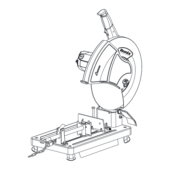
- Page 1 CUT OFF SAW 5935...
-
Page 2: Technical Specification
TECHNICAL SPECIFICATION Model 5935 Power 2200W Voltage 220V Frequency 50Hz No Load RPM RPM 3500 Blade Diameter 355mm Weight 21.8Kg Hex key, 355mm cutting Accessories wheel PART LIST Handle Lock On Switch Upper Blade ON/OFF Trigger Guard Carbon Brush Spindle Lock... - Page 3 FOR YOUR OWN SAFETY READ INSTRUCTION MANUAL BEFORE OPERATING TOOL SAVE IT FOR FUTURE REFERENCE GENERAL SAFETY PRECAUTIONS (For All Tools) 1. KNOW YOUR POWER TOOL. Read the owner’s manual carefully. Learn the tool’s applications and limitations, as well as the specific potential hazards peculiar to it.
- Page 4 12. SECURE WORK. Use clamps or a vise to hold work when practical. It’s safer than using your hand and it frees both hands to operate tool. 13. DON’T OVERREACH. Keep proper footing and balance at all times. 14. MAINTAIN TOOLS WITH CARE. Keep tools sharp and clean for best and safest performance.
-
Page 5: Specific Safety Rules
VOLTAGE WARNING: Before connecting the tool to a power source (receptacle, outlet, etc.) be sure the voltage supplied is the same as that specified on the nameplate of the tool. a power source with voltage greater than that specified for the tool can result in SERIOUS INJURY to the user –... - Page 6 for proper closing before each use. Do not operate the tool if wheel guard does not move freely and close instantly. Never clamp or tie the wheel guard into the open position. 8. Hold the handle firmly. 9. Keep hands away from rotating parts. 10.
-
Page 7: Installation
INSTALLATION SECURING CUT-OFF SAW 1. Base 2. Bolt holes This tool should be bolted with two bolts to a level and stable surface using the bolt holes provided in the tool’s base. This will help prevent tipping and possible personal injury. FUNCTIONAL DESCRIPTION CAUTION! - Page 8 CAUTION! - Before plugging in the tool, always check to see that the switch trigger actuates properly and returns to the “OFF” position when released. - When not using the tool, remove the lock off button and store it in a secure place.
- Page 9 STOPPER PLATE The stopper plate prevents the cut-off wheel from contacting the workbench or floor. When a new wheel is installed, set the stopper plate to position (A). When the wheel wears down to the extent that the lower portion of the workpiece is left uncut, set the stopper plate to position (B) to allow increased cutting capacity with a worn down wheel.
- Page 10 CAUTION! - Remember that narrow workpieces may not be secured safely when using the two, wider interval settings. Setting for desired cutting angle Guide plate To change the cutting angle, loosen the two hex bolts which secure the guide plate. Move the guide plate to the desired angle (0-45) and tighten the hex bolts securely.
- Page 11 REMOVING OR INSTALLING CUT-OFF WHEEL To remove the wheel, raise the safety guard. Press the shaft lock so that the wheel cannot revolve and use the socket wrench to loosen the hex bolt by turning if counterclockwise. Then remove the hex bolt, outer flange and wheel.
-
Page 12: Securing Workpiece
SECURING WORKPIECE By turning the vise handle counterclockwise and then flipping the vise nut to the left, the vise is released from the shaft threads and can be moved rapidly in and out. To grip workpieces, push the vise handle until the vise plate contacts the workpiece. - Page 13 1. Guide plate 2. Straight piece of wood (Spacer) 3. Over 45 mm (1-3/4”) long 4. Over 65 mm (2-9/16”) long 5. Over 190mm(7-1/2”)long - When cutting workpieces over 65 mm (2-9/19”) wide at an angle attach a straight piece of wood (spacer) over 190 mm (7-1/2”) long x 45 mm (1-3/4”) wide to the guide plate as shown in the figure.
-
Page 14: Operation
OPERATION Hold the handle firmly. Switch on the tool and wait until the wheel attains full speed before lowering gently into the cut when the wheel contacts the workpiece, gradually bear down on the handle to perform the cut. When the cut is completed, switch off the tool and WAIT UNTIL THE WHEEL HAS COME TO A COMPLETE STOP before returning the handle to the fully elevated position. -
Page 15: Carrying Tool
CARRYING TOOL Fold down the tool head to the position where you can attach the chain to the hook on the handle. MAINTENANCE CAUTION! Always be sure that the tool is switched off and unplugged before attempting to perform inspection or maintenance. Limit mark REPLACING CARBON BRUSHES Remove and check the carbon brushes regularly. - Page 16 Screwdriver Brush holder cap Use a screwdriver to remove the brush holder caps. Take out the worn carbon brushes, insert the new ones and secure the brush holder caps. To maintain product SFAETY and RELIABILITY, repairs, any other maintenance or adjustment should be performed by Makita Authorized or Factory Service Centers, always using Makita replacement parts.
Need help?
Do you have a question about the 5935 and is the answer not in the manual?
Questions and answers