Upright AB38 Service & Parts Manual
Aerial work platform
Hide thumbs
Also See for AB38:
- Operator's manual (84 pages) ,
- Operator's manual (20 pages) ,
- Operation and parts manual (24 pages)
Table of Contents
Advertisement
POWERED ACCESS
WARNING !
The AB38N Machine has been re-assessed to ensure
compliance to the Machinery Directive (2006/42/EC).
The Machine rating has been changed from:
2 People Indoors and Outdoors.
To
2 People Indoors and 1 Person Outdoors.
Please attach to the front cover of
your manual
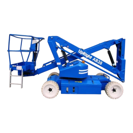
AB38
WORK PLATFORM
Advertisement
Table of Contents
Troubleshooting

Related Manuals for Upright AB38


Summary of Contents for Upright AB38
- Page 1 The AB38N Machine has been re-assessed to ensure compliance to the Machinery Directive (2006/42/EC). The Machine rating has been changed from: 2 People Indoors and Outdoors. 2 People Indoors and 1 Person Outdoors. Please attach to the front cover of your manual AB38 WORK PLATFORM...
- Page 2 NOTES: AB38 Work Platform...
- Page 3 When contacting UpRight Powered Access for service or parts information, be sure to include the MODEL and SERIAL NUMBERS from the equipment nameplate (nameplate types shown below). The AB38 Work Platform meets and exceeds the requirements of both prEN280 and ANSI A92.5 (1992). MODEL SERIAL NO.
- Page 4 NOTES: AB38 Work Platform...
- Page 5 UpRight , can be done, or the possible hazardous consequences of each conceivable way, nor could UpRight investigate all ways. Anyone using service procedures or tools, whether or not recom- Schematics mended by UpRight , must satisfy themselves thoroughly...
- Page 6 Foreword NOTES: AB38 Work Platform...
-
Page 7: Table Of Contents
Battery Charging .......... 4-3 Control System ..........1-2 Battery Cell Equalization ......4-4 Chassis ............1-2 Temperature Correction For AB38 Purpose & Limitations ...... 1-2 Electrolyte Readings ........4-4 Specifications ............. 1-3 Lubrication ............4-5 Notes ..............1-4 Grease Fittings ..........4-5 Slew Ring ............ - Page 8 Index ..............7-1 Cleaning & Inspection .........4-21 Illustrated Parts Breakdown ......7-2 Reassembly/Seal Replacement ....4-21 Installation .............4-22 inal Assembly AB38 ..........7-2 4.16 Telescopic Cylinder ........... 4-22 Chassis Assembly ............7-4 Removal ............4-22 Booms and Posts Assembly ........7-6 Disassembly ..........
- Page 9 Page Table Title Page AB38 Work Platform ........1-1 AB38 Work Platform Specifications ....1-3 Forklifting & Lifting The AB38 ....2-1 Controls & Indicators ........3-4 Manual Brake Release ........2-2 Preventative Maintenance ......4-2 Controls & Indicators ........3-5 Temperature Correction For Emergency Lowering ........3-9...
- Page 10 Section Contents NOTES: AB38 Work Platform...
-
Page 11: Introduction & Specifications
1.1 General Information ROTATION GEAR The AB38 is a quickly deployable self propelled aerial The Booms & Posts Assembly can be rotated to work platform, designed to raise two operators with provide up to 5.6 m (18.4 ft.) of side outreach,... -
Page 12: Drive & Steer Systems
AB38 PURPOSE & LIMITATIONS The AB38 Work Platform is restricted to low speed The purpose of the AB38 work platform is to provide a drive when the Platform is raised above the Boom quickly deployable variable height work platform. It is Rest Limit Switch. -
Page 13: Specifications
400 mm Diameter Steel Disc Wheel 15.75 inch Diameter Steel Disc Wheel Wheels/Tyres With Solid All Surface Tyres With Solid All Surface Tyres Automatic Spring Applied Automatic Spring Applied Braking Hydraulic Release Hydraulic Release 69.5 dB(A) 69.5 dB(A) AB38 Work Platform... -
Page 14: Notes
Section Introduction & Specifications NOTES: AB38 Work Platform... -
Page 15: Machine Preparation
The AB38 may be lifted by an overhead hoist/crane in to the vehicle in its freewheel state. the following manner: Four lifting straps capable of safely supporting the Refer to Section 2.6 which follows. total weight of the AB38 ( (3,550 Kg /7,826 lbs CE AB38 Work Platform... -
Page 16: Manual Brake Release
Section Machine Preparation When the AB38 is on the Truck it should then be When towing is completed, turn both Allen head made secure. socket screws in a counter clockwise direction until they rest firmly against the locking circlip. Chock the wheels of the AB38. -
Page 17: Notes
Machine Preparation Section NOTES: AB38 Work Platform... - Page 18 Section Machine Preparation NOTES: AB38 Work Platform...
-
Page 19: Operation
‘ON’ position. Depress the drive function button to electrical circuit, and its components, to an ECU. drive and the AB38 will also be able to steer. To steer the machine the Rocker should be pushed to the left The Drive function is operated by utilising two drive... -
Page 20: Design Features
The energy-efficient motor control units provides LOAD SENCING long battery life and smooth proportional control of The AB38 is fitted with a load sensing system de- the boom and drive functions. signed to comply with the requirements of : •... -
Page 21: Safety Rules & Precautions
Beaufort Force 6) WARNING NEVER change or modify operating or safety systems. Before using the AB38 Work Platform it is imperative to read, understand and follow the INSPECT the machine thoroughly for cracked welds, following Safety Rules and Precautions. loose hardware, hydraulic leaks, damaged control cable, loose wire connections and wheel bolts. -
Page 22: Controls & Indicators
Section Operation 3.2 Controls and Indicators The controls and indicators for operation of the AB38 Work Platform are shown in Figures 3-1 & 3-2. The name and function of each control and indicator are listed in Tables 3-1. The index numbers in the figure correspond to the index numbers in the table. -
Page 23: Controls & Indicators
Operation Section 6 7 8 Figure 3-1: Controls & Indicators AB38 Work Platform... -
Page 24: Pre-Operation Inspection
Check for missing or loose parts. If there are any concerns about the safe use SYSTEM FUNCTION INSPECTION or operation of the AB38 following this Pre-Operation Inspection DO NOT USE Turn both Chassis and Platform Emergency THE AB38 WORK PLATFORM. Contact your Stop switches ON (rotate clockwise). -
Page 25: Elevating & Lowering The Ab38 Work Platform
Enter Platform through the entrance at the side the clearances above, below and to the side of of the AB38 and ensure that the drop bar is in the Work Platform are sufficient. the lowered position. Lock the Entry Step in the Grasp the Joystick so that the Interlock Switch raised position. -
Page 26: Elevated
Section Operation To “STEER” the AB38 activate the Interlock The platform can be levelled from the Upper controls Switch while pushing the Steering Switch LEFT using the levelling function, depress and hold the or RIGHT to turn the wheels. Observe the tyres levelling button on the upper control box (see fig3-1) while manoeuvring to ensure proper direction. -
Page 27: Control From Ground Level
After use replace the Handpump Handle in the unauthorised operation. clips provided. Turn key switch to OFF and remove key to Reposition the cover on Chassis. prevent unauthorised operation. Recharge batteries in accordance with the instructions in section 4.2. AB38 Work Platform... - Page 28 Section Operation Hand Pump Hydraulic Valve Tank Valve Block Hand Pump Handle Figure 3-4: Manual Telescopic Retraction 3-10 AB38 Work Platform...
-
Page 29: Notes
Operation Section NOTES: AB38 Work Platform 3-11... - Page 30 Section Operation NOTES: 3-12 AB38 Work Platform...
-
Page 31: Maintenance
Referring to Section 3.0 and Section 6.0 will aid in WARNING understanding the operation and function of the various components and systems of the AB38 Work Platform and help in diagnosing and repair of the Before performing preventative maintenance machine. -
Page 32: Preventative Maintenance Table Key
Check the exterior of cable for Daily Section 4.13. pinching, binding or cable wear. Tyres / Check for damage. Daily Signature of Service Engineer Wheels Check/torque nuts - 50h/30d Front: 200 Nm (150 ft. lbs) _____________________________ Rear: 130 Nm (95 ft. lbs) AB38 Work Platform... -
Page 33: Battery Maintenance
Rinse thoroughly with clean, warm water. AC Voltage Selector Switch (110/220V) is in the Clean battery and cable contact surfaces to a bright correct position. metal finish whenever a cable is removed. AB38 Work Platform... -
Page 34: Battery Cell Equalization
-20ºC (-4ºF). However for this there are two provisions which must be met. The ISO#46 grade of hydraulic oil normally used in UpRight Work Platforms must be replaced with a SPECIFIC GRAVITY CONVERSION CHART grade suitable for these low temperature conditions. -
Page 35: Lubrication
The hydraulic oil may be of sufficient Grease Slew Ring evenly and sparingly every 10 temperature to cause burns. hours or 7 days as per the intervals in Table 4-1. DO NOT subject this area to powerwashing. AB38 Work Platform... -
Page 36: Setting Hydraulic Pressures
Release the Telescope RETRACT switch. Tighten locknut on main relief valve while holding the adjusting screw in position. Pressure Test Point Main Relief Slew Cross Valve Line Relief Valve Figure 4-4: Setting Main Relief Pressures Figure 4-3: Manifold Block AB38 Work Platform... -
Page 37: Slew Cross-Line Relief Valve
2. Remove the sling. 3. Push Lower Control Boom 1 Switch to “DOWN” and completely lower platform. 4. Turn Key Switch to “OFF” Figure 4-6: Supporting Elevating Assy. AB38 Work Platform... -
Page 38: Switch Adjustments
TILT SENSOR Rest is located on the side of the First Post on the AB38 Work Platform. The high speed drive can only Function: This limit switch is activated when the be operated when this switch is activated. When the internal sensor in the ‘Tilt Sensor’... -
Page 39: Tilt Sensor
Maintenance Section Figure 4-7: Tilt Sensor Elevating Assembly Lower Boom Upper Boom Switch Body Switch Head Figure 4-8: Boom Rest Limit Switch AB38 Work Platform... -
Page 40: Hydraulic Manifold
Inspect the manifold for cracks, thread damage and scoring where O-rings seal against internal and external surfaces. Wash and dry each component and check for thread damage, torn or cracked O-rings and proper operation. Replace parts and O-rings found unserviceable. 4-10 AB38 Work Platform... -
Page 41: Manifold Block Components
Solenoid Valve Coil Locking Nut Fitting, straight Bonded Washer Pressure Reduction Valve Main Relief Valve Pressure Test Point Telescopic Retraction Valve Cross Line Relief Valves Refer to Page 7-20 for part numbers Figure 4-9: Manifold Block Components AB38 Work Platform 4-11... -
Page 42: Hydraulic Pump
Push the springs back in place. Check the constant pressure on all the brushes, and the correct contact with the commutator. Replace the inspection/ventilation covers. Pressure Hose Suction Hose Capscrew Pump Assembly Electric Motor Figure 4-10: Hydraulic Pump 4-12 AB38 Work Platform... - Page 43 Check that foreign bodies or dirt have not entered the motor. Check that the ventilation holes are clean and not obstructed. Brush Bolt Spring Brush Box Support Brush Box Inspection/ Ventilation Cover Figure 4-11: Traction Motor Maintenance AB38 Work Platform 4-13...
-
Page 44: Electric Motor
Install new brushes and be sure they are free in Supply the holder. Install brush with the lead wires VOLTMETER positioned as when received. Place commutator cover on a work bench with brush assembly facing upward. Figure 4-12: Electrical Test Circuit 4-14 AB38 Work Platform... -
Page 45: Maintenance Intervals & Procedures
To solve this disassemble and reconnect in the proper way. Reversing the polarity will not solve this problem as this is a series wound motor. AB38 Work Platform 4-15... -
Page 46: Electric Motor Assembly
4.11 Pump Bearing Pulley End Cover Pulley End Bearing Armature Commutator Bearing Stator Housing Brush Housing Support Commutator End Cover Inspection Cover Brush Holders Brush Retaining Spring Brushes Retaining Bolt Coupling Figure 4-13: Electric Motor Assembly 4-16 AB38 Work Platform... -
Page 47: Drive Reduction Gearbox
F) / 30 C (86 VG 150 C (86 F) / 50 C (122 VG 320 Traction Motor Rear Wheel Drive Reduction Gearbox 12 O’Clock Filling Plug Hole Level 3 O’Clock Plug Hole Figure 4-14: Drive Reduction Gearbox AB38 Work Platform 4-17... -
Page 48: Changing The Oil
Loosen the five wheel nuts securing the Wheel Assembly to the Gearbox studs. 4.13 Torque Specifications Jack up the rear of the AB38 and chock the front wheels to prevent the machine from moving during the service. RETAINING BOLTS Remove the Wheel Assembly by unscrewing... -
Page 49: Lower Lift Cylinder
The Lower Lift Cylinder is heavy, so utilise appropriate lifting equipment to support the unit before removing pins. Ensure that the AB38 is on firm level ground, the Elevating Assembly is completely stowed, the Keyswitch is to the ‘OFF’ position and the Emergency Stop Button is pressed. -
Page 50: Reassembly/Seal Replacement
Breakdown. Cylinder Body Piston O-Ring Grease Nipple Piston Head Overcentre Cartridge Piston Seal End Cap Piston Locknut Rod And Pivot Washer Rod Seal Emergency Lowering O-Ring Valve Wiper Spacer Figure 4-16: Hydraulic Cylinder Component Breakdown 4-20 AB38 Work Platform... -
Page 51: Upper Lift Cylinder
The Upper Lift Cylinder is heavy, so utilise appropriate lifting equipment to support the unit before removing pins. Ensure that the AB38 is on firm level ground, the Elevating Assembly is completely stowed, the Keyswitch is to the ‘OFF’ position and the Emergency Stop Button is pressed. -
Page 52: Installation
Thread headcap onto barrel tube and hand tighten, then turn 1/4 turn further. REMOVAL Install the upper cylinder Overcentre valve. Ensure that the AB38 is on firm level ground, INSTALLATION the Elevating Assembly is completely stowed, the Keyswitch is to the ‘OFF’ position and the NOTE: Before installing Lift Cylinder check cylinder Emergency Stop Button is pressed. -
Page 53: Cleaning & Inspection
Replace any parts or seals found to be REMOVAL unserviceable. Ensure that the AB38 is on firm level ground, REASSEMBLY/SEAL REPLACEMENT the Elevating Assembly is completely stowed but slewed away from centre, the Keyswitch is... -
Page 54: Cleaning & Inspection
Install a new piston seal on the piston. Barrel End Pivot Pin Pin Lock Plate Install the headcap on one end of the cylinder Rod End Pivot Pin barrel. Lubricate the piston seal and install the rod & Figure 4-20: Master Levelling Cylinder 4-24 AB38 Work Platform... -
Page 55: Master Levelling Cylinder
REMOVAL polished the affected parts should be replaced. Replace any parts or seals found to be Ensure that the AB38 is on firm level ground, unserviceable. the Elevating Assembly is completely stowed, the Keyswitch is to the ‘OFF’ position and the REASSEMBLY/SEAL REPLACEMENT Emergency Stop Button is pressed. -
Page 56: Slave Levelling Cylinder
Unscrew the piston nut and remove piston and REMOVAL headcap from the cylinder rod. Remove the piston static O-ring from the Ensure that the AB38 is on firm level ground, cylinder rod. the Elevating Assembly is completely stowed, Remove the piston seal from the piston. -
Page 57: Installation
Master Cylinder. Remove the rod end pivot pin. Move cylinder backwards and allow to hang freely. Loosen, but do not fully disconnect, the hose fitting at ‘B’. Prepare to activate the Levelling AB38 Work Platform 4-27... -
Page 58: Adjustment Of Overcentre Valves
Section Maintenance 4.20 4.20 Adjustment of Overcentre Valves on AB38 Lift Cylinders (Figure 4-22) The valve supplier delivers the Overcentre valve preset to specification and SHOULD NOT be adjusted by the user. In the event of the valve having been tampered with the advisable course of action is to fit a replacement cartridge. -
Page 59: Notes
Maintenance Section 4.21 NOTES: AB38 Work Platform 4-29... - Page 60 Section Maintenance 4.21 NOTES: 4-30 AB38 Work Platform...
-
Page 61: Troubleshooting
Re-evaluate the schematics and check all understanding the operation and function of the suspect components electrically, hydraulically various components and systems of the AB38 Work and mechanically to determine if they are at Platform and help in diagnosing and repair of the fault. - Page 62 4. Brakes engaged Check that the coil of V1 leaking and clean. Check that Brake solenoid is energised for internally or O-Rings are intact. Adjust V1 ( CT11 ) is not approximately 4 seconds, needs adjusting. or replace. energising to by a delay module, when AB38 Work Platform...
- Page 63 If no 4. Tacho faulty. Repair or replace. lines. current is being fed to this Machine 1. The AB38 is not Lower the Elevating coil then replace the cable will not in the stowed Assembly. feeding the coil or replace drive in position.
-
Page 64: Fault Codes
Section Troubleshooting 5.2 Fault Codes. The AB38 is equipped with a fault detection system, if you have a faulty component, bad electrical connection or start up error a fault code will be displayed on the read out located on the upper control box. - Page 65 Steer Left, Coil fault Level Platform Up, Coil fault Level Platform Down, Coil fault Brake Chamber Fill, Coil fault Brake Chamber Empty, Coil fault Forward Contactor, Coil Fault Reverse Contactor, Coil fault Low Battery fault Pump Contactor, Coil fault AB38 Work Platform...
- Page 66 Section Troubleshooting NOTES: AB38 Work Platform...
-
Page 67: Introduction
6.0 Introduction This section contains electrical and hydraulic power schematics and associated information for maintenance purposes. INDEX Page Electrical Assy, J1 Harness Electrical Assy, J2 Harness Electrical Assy, J1 Harness & Connections Hydraulic Legend Hydraulic Schematic 6.11 AB38 Work Platform... - Page 68 Schematics Section NOTES: AB38 Work Platform...
-
Page 69: Electrical Schematics
Schematics Section 6.1. Electrical Schematics J1 Harness AB38 Work Platform... - Page 70 Schematics Section 6.1. Electrical Schematics AB38 Work Platform...
- Page 71 Schematics Section 6.1. Electrical Schematics J1 Harness & Connections AB38 Work Platform...
- Page 72 Schematics Section NOTES: AB38 Work Platform...
- Page 73 Schematics Section AB38 Work Platform Electrical Schematic...
- Page 74 Schematics Section TOP VIEW Electrical Schematic AB38 Work Platform...
-
Page 75: Hydraulic Schematics
Send oil to the annular or full- On main Directional bore side of the Boom1 manifold block. Control Valve. cylinder. Levelling Send oil to the annular or full- On main Directional bore side of the levelling manifold block. Control Valve. cylinders. AB38 Work Platform... - Page 76 Section Schematics NOTES: 6-10 AB38 Work Platform...
-
Page 77: Main Manifold Block
CYL5 - MASTER CYL3- TELE MOT1 B2 A3 B3 A4 B4 A5 BRAKE CLRV CLRV (RV) BOOM1 TELE SLEW STEER BOOM2 F L1 Main Manifold Block MMB - RESEVOIR / HYDRAULIC TANK AB38 Work Platform Figure 6-3, 4 : Hydraulic Schematic 6-11... - Page 78 Schematics Section NOTES: 6-12 AB38 Work Platform...
-
Page 79: Index
7.1 Index Assembly Page This section lists and illustrates the replaceable assemblies and parts of the AB38 Work Platform as inal Assembly AB38 ..........7-2 manufactured by UpRight UK. Chassis Assembly ............7-4 Each parts list contains the component parts for that assembly indented to show relationship where Booms and Posts Assembly ........ -
Page 80: Final Assembly Ab38
Section Illustrated Parts Breakdown FINAL ASSEMBLY AB38 - 500200-001 (ANSI Version) 500200-000 (CE Version) ITEM PART NO. DESCRIPTION QTY. 500202-000 Chassis Assembly 500201-000 Booms and Posts Assembly 057603-000 Cage and Cradle Assembly 057580-000 Drive Reduction Gearbox Assembly 057568-000 Traction Motor Assembly - Right Hand... - Page 81 Illustrated Parts Breakdown Section AB38 Work Platform...
- Page 82 AB38 STEERING CYLINDER 056065-035 MOUNTING BOLTS M12 056021-012 SPRING WASHER 057573-000 CHARGER 220/110VAC 50/60Hz 057586-000 HORN 500234-002 AB38 CHASSIS SIDE DROP PANEL - WITH SLOTS 500410-001 DROP PANEL LOCK (Complete) 501074-000 BATTERY 6V 220AH 010154-000 TERMINAL COVERS 501862-000 MOTOR CONTROLLER ASSEMBLY...
- Page 83 Illustrated Parts Breakdown Section AB38 Work Platform...
- Page 84 AB38 SECOND POST WELDMENT 058413-000 AB38 LOWER BOOM WELDMENT 058414-001 OUTER TELE BOOM WELDMENT 058415-001 INNER TELESCOPIC BOOM WELDMENT 500245-000 AB38 HOSE & CABLE COVER 500265-000 COVER FOR ENERGY CHAIN CHANNEL 057727-000 TWIST SCREW FASTENER 500266-000 ENERGY CHAIN SUPPORT CHANNEL 500468-000...
- Page 85 Illustrated Parts Breakdown Section AB38 Work Platform...
- Page 86 PART NO. DESCRIPTION QTY. 057521-003 CAGE RAIL ASSY. 057524-000 DROP BAR ASSY. 057523-000 CONTROL BOX MOUNTING PLATE 501864-000 AB38 UPPER CONTROL BOX 010076-000 MANUAL HOLDER 501970-000 AB38 CAGE FLOOR WELDMENT 058251-000 LADDER LOCKING LATCH 057348-000 LADDER 501886-000 OVERLOAD UNIT(Ansi 509791-000)
- Page 87 Illustrated Parts Breakdown Section AB38 Work Platform...
- Page 88 M12 NYLOCK NUT 057347-001 LADDER 058251-000 LOCKING CATCH 057405-000 LADDER BUSHING 509466-000 ROLL PIN ROTATE LINK Note : Ensure that items 11 and 18 (M12 screw and drilled nut with pin) remain loose, these are safety bolts. 7-10 AB38 Work Platform...
- Page 89 Illustrated Parts Breakdown Section AB38 Work Platform 7-11...
- Page 90 CAGE ROTATOR ASSEMBLY 057669-000 ITEM PART NO. DESCRIPTION QTY. 057665-000 WHEEL HUB 057664-000 THRUST BEARING 057662-000 PIVOT BOSS 057663-000 PIVOT PIN 057585-000 COVER PLATE 057584-000 OUTER HUB BEARING 057583-000 INNER HUB BEARING 057582-000 STUD 057669-002 PLASTIC BUSHING 7-12 AB38 Work Platform...
- Page 91 Illustrated Parts Breakdown Section AB38 Work Platform 7-13...
-
Page 92: Drive Reduction Gearbox Assembly
STUD M15 X 1.5 O-RING BEARING SCREW RETAINING RING CIRCLIP RETAINING RING NOTE: ITEMS 5,7,8,11,12,13,15,29,44 & 46 FORM THE SEAL KIT FOR THE DRIVE REDUCTION GEARBOX ASSEMBLY. THE PART NUMBER FOR THE COMPLETE SEAL KIT IS 057580-010 7-14 AB38 Work Platform... - Page 93 Illustrated Parts Breakdown Section AB38 Work Platform 7-15...
-
Page 94: Traction Motor Assembly
DESCRIPTION QTY. MOTOR MOUNTING FACE SEAL CIRCLIP BEARING COOLING FAN COMMUTATOR BEARING FIELD WINDINGS COMMUTATOR COVER BRUSH BOXES SUPPORT END FACE VENT / INSPECTION CAP 057698-000 BRUSH 057699-000 BRUSH SPRINGS 057569-001 TACHO ADAPTOR KIT 057569-000 TACHO 7-16 AB38 Work Platform... - Page 95 Illustrated Parts Breakdown Section AB38 Work Platform 7-17...
-
Page 96: Motor/Pump Assembly
CIRCLIP COOLING FAN COMMUTATOR BEARING COMMUTATOR COVER BRUSH HOUSING SUPPORT 058863-000 BRUSH END HOUSING TERMINAL BLOCK VENT / INSPECTION CAP NOTE: THE PART NUMBER FOR THE MOTOR ASSEMBLY (ALL ITEMS FROM 2 TO 17) IS 058861-000 7-18 AB38 Work Platform... - Page 97 Illustrated Parts Breakdown Section AB38 Work Platform 7-19...
-
Page 98: Rear & Front Wheel Kit
FRONT WHEEL TYRE & RIM ASSY. REAR & FRONT WHEEL KIT (BLACK) ITEM PART NO. DESCRIPTION QTY. 057578-000 WHEEL NUT - M14 057668-000 REAR WHEEL TYRE & RIM ASSY. 057666-000 WHEEL NUT - M16 057667-001 FRONT WHEEL TYRE & RIM ASSY. 7-20 AB38 Work Platform... - Page 99 Illustrated Parts Breakdown Section AB38 Work Platform 7-21...
- Page 100 SLEW MOTOR, WORM DRIVE UNIT & SLEW BEARING ASSEMBLY 500284-001 ITEM PART NO. DESCRIPTION QTY. 500284-000 AB38 WORM DRIVE UNIT & SLEW BEARING ASSEMBLY 500280-000 BOLT 5/8” -11 UNC x 3 1/2” 500281-000 WASHER M16 HARDENED 500285-000 AB38 SLEW MOTOR...
- Page 101 Illustrated Parts Breakdown Section AB38 Work Platform 7-23...
-
Page 102: Manifold Block Assembly
RETRACTION VALVE LEVER) ARE NOT REQUIRED FOR MACHINES MANUFACTURED TO COMPLY WITH THE ANSI STANDARD. THEREFORE THE PORT INDICATED BY ITEM 9 ON THE HYDRAULIC MANIFOLD IS BLANKED. THE PART NUMBER FOR THIS BLANK IS 500261-003 7-24 AB38 Work Platform... - Page 103 Illustrated Parts Breakdown Section AB38 Work Platform 7-25...
-
Page 104: Lower Lift Cylinder Assembly
GREASE NIPPLE 058516-000 AB38 BOSS CAPHEAD SCREW M8 NOTE: ITEMS 6 TO 10 INCLUSIVE, 12 & 14 FORM THE SEAL KIT FOR THE AB38 LOWER LIFT CYLINDER. THE PART NUMBER FOR THIS SEAL KIT IS 500457-000 NOTE: ITEMS 17, 18 & 19 ARE NOT INCLUDED AS PART OF THE CYLINDER ASSEMBLY. - Page 105 Illustrated Parts Breakdown Section AB38 Work Platform 7-27...
-
Page 106: Upper Lift Cylinder Assembly
PISTON SEAL PISTON LOCKNUT WASHER 057048-000 GREASE NIPPLE NOTE: ITEMS 6 TO 10 INCLUSIVE, 12 & 14 FORM THE SEAL KIT FOR THE AB38 UPPER LIFT CYLINDER. THE PART NUMBER FOR THIS SEAL KIT IS 500458-000 7-28 AB38 Work Platform... - Page 107 Illustrated Parts Breakdown Section AB38 Work Platform 7-29...
-
Page 108: Telescopic Cylinder Assembly
PISTON HEAD SEE NOTE PISTON SEAL PISTON LOCKNUT WASHER NOTE: ITEMS 6 TO 9 INCLUSIVE, 12 & 14 FORM THE SEAL KIT FOR THE AB38 TELESCOPIC CYLINDER. THE PART NUMBER FOR THIS SEAL KIT IS 500459-000 7-30 AB38 Work Platform... - Page 109 Illustrated Parts Breakdown Section AB38 Work Platform 7-31...
-
Page 110: Steering Cylinder Assembly
SEE NOTE WIPER SEE NOTE ROD SEAL SEE NOTE O-RING 057048-000 GREASE NIPPLE NOTE:ITEMS 3, 5, 6 & 7 FORM THE SEAL KIT FOR THE AB38 STEERING CYLINDER. THE PART NUMBER FOR THIS SEAL KIT IS 500460-000 7-32 AB38 Work Platform... - Page 111 Illustrated Parts Breakdown Section AB38 Work Platform 7-33...
-
Page 112: Master/Slave Cylinder Assembly
PISTON SEAL PISTON LOCKNUT WASHER 057048-000 GREASE NIPPLE NOTE: ITEMS 6 TO 10 INCLUSIVE, 12 & 14 FORM THE SEAL KIT FOR THE AB38 MASTER OR SLAVE CYLINDER. THE PART NUMBER FOR THIS SEAL KIT IS 058750-000 7-34 AB38 Work Platform... - Page 113 Illustrated Parts Breakdown Section AB38 Work Platform 7-35...
- Page 114 501895-000 HARNESS, LC 3 TO FUSE 501896-000 HARNESS, MTR CNTRL A2 TO FWD 4 501897-000 HARNESS, MTR CNTRL B+ TO LC 6 501897-000 HARNESS,MTR CNTRL M- TO FWD 6 501897-000 HARNESS,MTR CNTRL B+ TO PC 3 7-36 AB38 Work Platform...
- Page 115 Illustrated Parts Breakdown Section AB38 Work Platform 7-37...
-
Page 116: Lower Control Box Assembly
Section Illustrated Parts Breakdown AB38 LOWER CONTROL BOX ASSEMBLY 500490-000 (Harnesses are not part of this assembly) ITEM PART NO. DESCRIPTION QTY. 501867-000 E-STOP SWITCH C/W CONTACT BLOCK 501872-000 ANALOG ROCKER 501870-000 OVERLAY (DECAL) NOTE: THE PART NUMBER FOR THE... - Page 117 Illustrated Parts Breakdown Section AB38 Work Platform 7-39...
-
Page 118: Upper Control Box Assembly
501864-000 PLATFORM CONTROLLER 501865-000 PC BOARD ASSY 501866-000 KEY SWITCH 501867-000 E-STOP SWITCH C/W CONTACT BLOCK 501869-000 OVERLAY (DECAL) 501881-000 UPPER CONTROL BOX (BOX ONLY) 501882-000 JOYSTICK 501882-001 JOYSTICK, RUBBER STEERING BOOT 501882-000 JOYSTICK, RUBBER BOOT 7-40 AB38 Work Platform... - Page 119 Illustrated Parts Breakdown Section AB38 Work Platform 7-41...
- Page 120 HARNESS - BATTERY - BATTERY (LONG) 502594-000 HARNESS - BATTERY DISCONNECT - BATTERY POSITIVE AND NEGATIVE. 502595-000 HARNESS - BATTERY DISCONNECT - FUSE AND MOTOR CONTROLLER B- 502596-000 HARNESS - BATGTERY CHARGER - LINE CONTACTOR AND BETTERY NEG 7-42 AB38 Work Platform...
- Page 121 Illustrated Parts Breakdown Section AB38 Work Platform 7-43...
-
Page 122: Hose Assembly
HOSE ASSY, 1/4” M1T 1270 mm BF-B90 MANIFOLD TO BRAKE T PIECE 500355-000 HOSE ASSY, 1/4” M1T 430 mm BF-B90 T PIECE TO BRAKE 500355-000 HOSE ASSY, 1/4” M1T 430 mm BF-B90 T PIECE TO BRAKE 058352-000 T PIECE 7-44 AB38 Work Platform... - Page 123 Illustrated Parts Breakdown Section AB38 Work Platform 7-45...
- Page 124 DECAL - LOWER CONTROL BOX 500257-001 DECAL - AB38N LOGO 057695-000 DECAL - BALLAST STRIP 502480-000 DECAL - EMERGENCY LOWERING 057696-000 DECAL - ‘UpRight ’ LOGO 057429-000 DECAL - BATTERY FLUID LEVEL 057430-000 DECAL - EXPLOSION HAZARD 058881-001 DECAL - HAZARD TAPE 058080-000...
- Page 125 Illustrated Parts Breakdown Section AB38 Work Platform 7-47...
- Page 126 Illustrated Parts Breakdown DECAL KIT International English (CE) 500206-000 ITEM PART NO. DESCRIPTION QTY. 500264-000 DECAL - ‘UpRi ght AB38’ BOOM 501870-000 DECAL - LOWER CONTROL BOX 500257-000 DECAL - AB38 LOGO 057695-000 DECAL - BALLAST STRIP 502480-000 DECAL - EMERGENCY LOWERING 057696-000 DECAL - ‘UpRight ’...
- Page 127 Illustrated Parts Breakdown Section AB38 Work Platform 7-49...
- Page 128 ITEM PART NO. DESCRIPTION QTY. ITEM PART NO. DESCRIPTION QTY. 500264-000 DECAL - ‘UpRi ght AB38’ BOOM 500264-000 DECAL - ‘UpRight AB38’ BOOM 501870-000 DECAL - LOWER CONTROL BOX 501870-000 DECAL - LOWER CONTROL BOX 500257-000 DECAL - AB38 LOGO...
- Page 129 Illustrated Parts Breakdown Section AB38 Work Platform 7-51...
-
Page 130: Options List
OPTION LIST The options outlined opposite are available ITEM PART NO. DESCRIPTION 058191-000 AB38 OPTION, POWER TO PLATFORM 110V from UpRight when ordering a new 058191-001 AB38 OPTION, POWER TO PLATFORM 220V 500123-000 AB38 OPTION, DESCENT ALARM machine or as a spare part to be... - Page 131 Illustrated Parts Breakdown Section NOTES: AB38 Work Platform 7-53...
- Page 132 Local Distributor: Lokaler Vertiebshändler: Distributeur local: El Distribuidor local: Il Distributore locale: Europe TEL: +1 (559) 443 6600 TEL: +44 (0) 845 1550 058 FAX: +1 (559) 268 2433 FAX: +44 (0) 195 2299 948 www.upright.com 500422-001...
-
Page 133: Ab38 Work Platform
Technician’s Print AB38 Work Platform Electrical Schematic...
Need help?
Do you have a question about the AB38 and is the answer not in the manual?
Questions and answers