Sign In
Upload
Manuals
Brands
Upright Manuals
Lifting Systems
UI 12 M-Lift
Upright UI 12 M-Lift Manuals
Manuals and User Guides for Upright UI 12 M-Lift. We have
1
Upright UI 12 M-Lift manual available for free PDF download: Service And Parts Manual
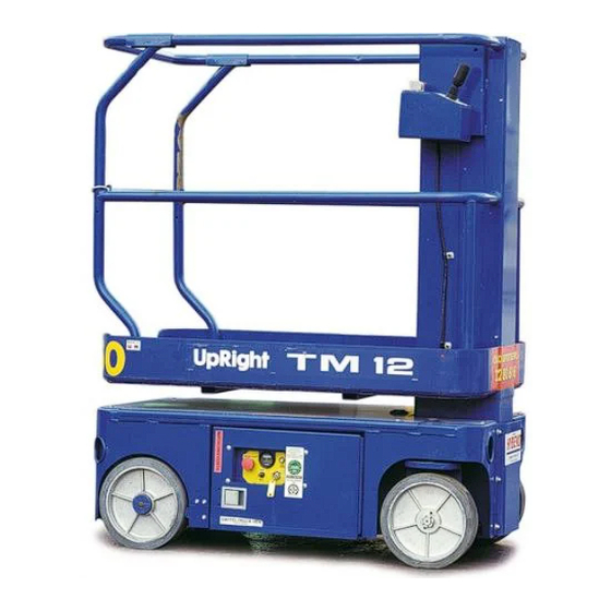
Upright UI 12 M-Lift Service And Parts Manual (146 pages)
Work Platform
Brand:
Upright
| Category:
Lifting Systems
| Size: 8 MB
Table of Contents
Table of Contents
6
Introduction
7
General Description
7
Special Limitations
8
Platform Capacity
8
Manual Force
8
Beaufort Scale
8
Controls and Indicators
9
Pre-Operation Safety Inspection
10
System Function Inspection
11
Operation
12
Travel with Platform Lowered
12
Steering
12
Elevating Platform
12
Travel with Platform Elevated
12
Lowering Platform
12
Emergency Lowering
13
After Use each Day
13
By Truck
14
By Crane
14
By Forklift
14
Transporting the Machine
14
Maintenance
15
Blocking the Elevating Assembly
15
Installation
15
Removal
15
Hydraulic Fluid
15
Check Hydraulic Fluid
15
Battery Maintenance
16
Battery Charging
17
Inspection and Maintenance Schedule
18
Daily Preventative Maintenance Checklist
19
Labels
20
Specifications
25
Section 1
27
Hazard Indicators
28
Table 1-1: Torque Specifications for Hydraulic Components
29
Table 1-2: Torque Specifications for SAE Fasteners
29
Torque Specifications
29
Table 1-3: Torque Specifications for Metric Fasteners, U.S. Customary Units
30
Table 1-4: Torque Specifications for Metric Fasteners, si Units
30
Date Code Identification on Hoses
31
Special Tools
31
Figure 1-1: Upright Connector Kits
32
Figure 1-2: Upright Male Connector
32
Figure 1-3: Upright Female Connector
32
Upright Connectors
32
Figure 1-4: Locking Finger, Upright Connector
33
Figure 1-5: Heavy Duty Upright Connector
33
Hydraulic Manifold Repair
34
Cylinder Repair
35
Electric Motors
36
Figure 1-6: Electric Motor Service
36
Figure 1-7: Electric Motor Brushes
37
Battery Maintenance
38
Table 1-5: Specific Gravity and Battery Voltage
39
Table 1-6: Battery Charging, Upright Electric and Bienergy Machines
40
Table 1-7: Battery Charger Troubleshooting
41
Figure 1-9: Occupied Surface Area
42
Floor Loading
42
Hydraulic Fluid
43
Long Term Storage
44
Section 2
45
Installation
47
Removal
47
Supporting Elevating Assembly
47
Preventative Maintenance
48
Preventative Maintenance Check List
49
Parts Location
50
General Lubrication
52
Batteries
53
Battery Maintenance
53
Battery Replacement
53
Hydraulic Oil Tank and Filter
54
Hydraulics
54
Hydraulic Pump
55
Cylinders
61
Depression Cylinder
61
Brake Cylinder
62
Steering Cylinder
63
Lift Cylinder
64
Drive Motors
65
Installation
65
Removal
65
Elevating Assembly
66
Elevating Assembly Wear Inspection
67
Chain Elongation Inspection
68
Chain Tension Inspection
68
Installation of Elevating Assembly
69
Removal of Elevating Assembly
69
Tilt Sensor
70
Controls
71
Platform Controls
71
Chassis Controls
73
Controller
74
I/O (Circuit) Board
74
Motor Controller and I/O Board Dip Switch Settings | Serial # M30176 - M30338
74
Section 3
75
Table of Contents
75
Ist of
76
Ist of Ables
76
Adjustment Procedures
77
Checking Pump Pressures
77
General Procedure
77
Technical Support
77
Troubleshooting Procedures
77
Adjusted Dip Switch Settings
78
Default Dip Switch Settings
78
Motor Controller Dip Switch Settings
78
I/O Board Dip Switch Settings
79
LED Fault Codes
80
Leds at I/O Board
81
I/O Board Inputs and Outputs
82
Fault Codes Introduction
85
3-10 Fault Codes
86
Electric
87
Section 4
89
Able of Ontents
89
Electric Schematic | Serial # M30176-M30338
90
Hydraulic
90
Hydraulic Schematic | Serial # M30176-M30338
92
Schematic (J1 Harness) | Serial # M30339-M30642
94
Cable Assembly (J1 Harness) | Serial # M30339-M30642
95
Electric Schematic | Serial # M30339-M30642
96
Hydraulic Schematic | Serial # M30339-M30642
97
P Marts Anual
99
Final Assembly 107000-000 | Serial # M30176-M30338
100
Basic Assembly
104
Chassis Assembly, 1 of 4
106
Chassis Assembly, 2 of 4
107
Chassis Assembly, 3 of 4
108
Chassis Assembly, 4 of 4
109
107011-020 | Serial # M30176-M30338
110
Hose Kit
110
505007-000 | Serial # M30339-M30642
112
Hose Kit
112
Control Valve Assembly 101120-021 | Serial # M30176-M30338
114
Control Valve Assembly 503800-000 | Serial # M30339-M30642
115
Controller Assembly 107010-000 | Serial # M30176-M30338
116
PQ Controller 065512-000 | Serial # M30176-M30338
117
Electrical Box Assembly 107008-000 | Serial # M30176-M30338
118
Level Sensor Wire Assembly
119
Control Cable 107009-000 | Serial # M30176-M30338
120
Lower Control Cable 107193-000 | Serial # M30176-M30338
121
Chassis Control Cable 107194-001 | Serial # M30176-M30338
122
Capacitor Harness 107054-001 | Serial # M30176-M30338
123
Valve Block Cable 107192-000 | Serial # M30176-M30338
124
Lift Cylinder
125
Brake\Steer Cylinder
126
Depression Cylinder
127
Drive Relief Valve Assembly 107006-000 | Serial # M30176-M30338
128
Flow Control Valve 107061-000 | Serial # M30176-M30338
129
Hydraulic Tank Assembly
130
107012-010 | Serial # M30176-M30338
131
Label Kit
131
Voltage/Hourmeter Option 107032-000 | Serial # M30176-M30338
132
Lift Overload Option 107030-000 | Serial # M30176-M30338
133
107031-000 | Serial # M30176-M30338
134
Horn Option
134
Hydraulic Schematic 107015-001 | Serial # M30176-M30338
135
Electrical Schematic 107016-000 | Serial # M30176-M30338
136
ITT Electrical Schematic | Serial # M30339-M30642
137
ITT Controller | Serial # M30339-M30642
138
ITT Controller Assembly | Serial # M30339-M30642
140
Serial # M30339-M30642
140
ITT Control Cable Assembly | Serial # M30339-M30642
142
ITT Universal Compartment | Serial # M30339-M30642
144
Advertisement
Advertisement
Related Products
Upright ULII-25
Upright ULII-32
Upright ULII-40
Upright ULII-48
Upright upright
Upright UL25
Upright UL32
Upright UL40
Upright 6013
Upright 9300
Upright Categories
Lifting Systems
Scissor Lifts
Boom Lifts
Construction Equipment
Switch
More Upright Manuals
Login
Sign In
OR
Sign in with Facebook
Sign in with Google
Upload manual
Upload from disk
Upload from URL