Table of Contents
Advertisement
Quick Links
Download this manual
See also:
User Manual
Advertisement
Table of Contents

Related Manuals for Peak PCAN-cPCI


Summary of Contents for Peak PCAN-cPCI
- Page 1 PCAN-cPCI CompactPCI to CAN Interface User Manual...
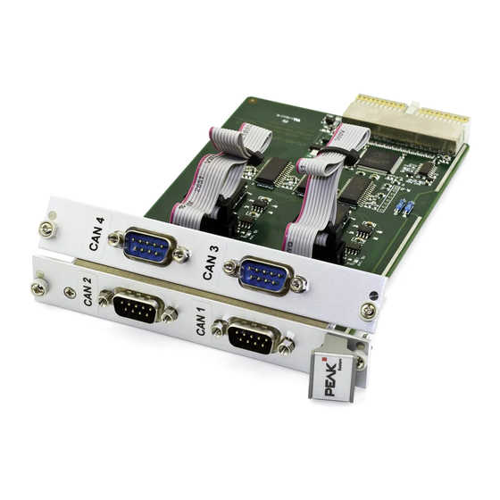
- Page 2 CAN connections The cover picture shows the product PCAN-cPCI Quad Channel opto-decoupled. The product version Dual Channel opto-decoupled has an identical form factor but differs in equipment (no additional front blind with CAN connectors) and in the board's components.
-
Page 3: Table Of Contents
PCAN-cPCI – User Manual Contents Introduction Properties at a Glance Prerequisites for the Operation Scope of Supply Installation Installing the Software and the PCAN-cPCI Card Connecting the CAN Bus Supplying External Devices via the CAN Connector Software CAN Monitor PCAN-View for Windows... -
Page 4: Introduction
PCAN-cPCI – User Manual Introduction The PCAN-cPCI card provides two or four CAN channels in computers with CompactPCI slots. Software interfaces exist for different operating systems, so programs can easily access a connected CAN bus. Tip: At the end of this manual (Appendix C) you can find a... -
Page 5: Prerequisites For The Operation
PCAN-cPCI – User Manual Note: This manual describes the use of the PCAN-cPCI card with Windows. You can find device drivers for Linux and the corresponding application information on PEAK-System's website under www.peak-system.com/linux. Prerequisites for the Operation The following prerequisites must be given, so that the PCAN-cPCI... -
Page 6: Installation
PCAN-cPCI – User Manual Installation This chapter deals with the software setup for the PCAN-cPCI card under Windows, the installation of the card in the computer, and the connection of a CAN bus. Installing the Software and the PCAN- cPCI Card We recommend that you setup the driver before installing the PCAN-cPCI card into the computer. - Page 7 PCAN-cPCI – User Manual Do the following to install the PCAN-cPCI card in the computer: At the Quad Channel version of the PCAN-cPCI card (IPEH- 003022) connect the cables of the additional front blind to the 10-pin ports J1 (CAN 3) and J2 (CAN 4).
- Page 8 Windows Device Manager. Concerning the software part the CompactPCI standard is fully compatible to the PCI standard, thus the driver for the PCAN-PCI card is used in the end. Figure 2: Representation of the PCAN-cPCI card in the Windows Device Manager...
-
Page 9: Connecting The Can Bus
102 DS. Figure 3: Pin assignment High-speed CAN (view onto a male D-Sub connector on the PCAN-cPCI card) With the pins 1 and 9 devices with low power consumption (e.g. bus converters) can be directly supplied via the CAN connector. At delivery these pins are not assigned. -
Page 10: Supplying External Devices Via The Can Connector
A 5-Volt supply can optionally be routed to pin 1 and/or pin 9 of a D- Sub connector (independently for each connector) by setting solder bridges on the PCAN-cPCI card. Thus devices with low power consumption (e.g. bus converters) can be directly supplied via the CAN connector. - Page 11 PCAN-cPCI – User Manual Figure 4: Positions of the solder fields on the PCAN-cPCI card for a 5-Volt supply, JP1 to JP4 for CAN channels 1 to 4 5-Volt supply → None Pin 1 Pin 9 Pin 1 + Pin 9...
-
Page 12: Software
PCAN-cPCI – User Manual Software This chapter deals with the provided software and the software interface to the PCAN-cPCI card. CAN Monitor PCAN-View for Windows PCAN-View for Windows is a simple CAN monitor for viewing and transmitting CAN messages. Figure 5: The main window of PCAN-View for Windows... - Page 13 PCAN-cPCI – User Manual In order to start directly from the supplied CD without prior installation use the navigation program (Intro.exe), go to English > Tools, and in the entry PCAN-View for PCI card click on Start. A dialog box for the selection of the CAN hardware as well as the setting of the CAN parameters appears after the program start.
-
Page 14: Linking Own Programs With Pcan-Light
PEAK-System or one of its partners. If a CAN hardware component of third party suppliers should be compatible to one of PEAK-System, then you are not allowed to use or to pass on the driver software of PEAK-System. -
Page 15: Frequently Asked Questions (Faq)
Yes. You need a bus converter to do so. Instead of a High-speed PEAK-System offers bus converter CAN bus I would like to modules for different transmission connect another one standards that are plugged between the (e.g. Low-speed CAN). PCAN-cPCI card and the CAN bus. Is this possible? -
Page 16: Technical Specifications
PCAN-cPCI – User Manual Technical Specifications Connectors Computer CompactPCI connector J1 (110 Pin, 32 Bits) D-Sub (m), 9 pins, pin assignment according to CiA recommendation 102 DS Galvanic isolation up to 500 V (separate for each CAN connector) Specification ISO 11898-2 High-speed CAN (up to 1 MBit/s) 2.0A (standard format) and 2.0B (extended format) - Page 17 PCAN-cPCI – User Manual Environment Operating temperature -40 – +85 °C (-40 – +185 °F) Temperature for storage -40 – +125 °C (-40 – +257 °F) and transport Relative humidity 15 – 90 %, not condensing EN 55024:2003-10 EN 55022:2007-04...
-
Page 18: Appendix Ace Certificate
PCAN-cPCI – User Manual Appendix A CE Certificate... -
Page 19: Appendix B Dimension Drawings
PCAN-cPCI – User Manual Appendix B Dimension Drawings Figure 7: Top view PCAN-cPCI card... - Page 20 PCAN-cPCI – User Manual Figure 8: View of the front blind The figures don't show the original size.
-
Page 21: Appendix C Quick Reference
Afterwards, insert the PCAN-cPCI card into an empty CompactPCI slot of the switched off (de-energized) computer. At the next start of Windows the PCAN-cPCI card is recognized by Windows and the driver is initialized. After the driver has been successfully installed you can find the entry “PEAKCAN PCI-card”...
Need help?
Do you have a question about the PCAN-cPCI and is the answer not in the manual?
Questions and answers