IEI Technology WSB-H610 User Manual
Full-size cpu card, single board computers
Hide thumbs
Also See for WSB-H610:
- Quick installation manual (13 pages) ,
- User manual (146 pages) ,
- Quick installation manual (13 pages)
Table of Contents
Advertisement
Quick Links
Advertisement
Table of Contents

Subscribe to Our Youtube Channel
Related Manuals for IEI Technology WSB-H610


Summary of Contents for IEI Technology WSB-H610
- Page 1 WSB-H610 PICMG 1.0 CPU Card MODEL: WSB-H610 Full-Size PICMG 1.0 CPU Card Supports 32nm LGA1155 Intel® Core™ i7/i5/i3/Pentium®/Celeron® CPU, Intel® H61 Chipset, DDR3, VGA/DVI-D, Dual Realtek PCIe GbE, USB 2.0, COM, SATA 3Gb/s, HD Audio and RoHS User Manual Page i...
- Page 2 WSB-H610 PICMG 1.0 CPU Card Revision Date Version Changes 25 April, 2014 1.02 Modified LAN pinouts Updated Chapter 2: Packing List 8 July, 2013 1.01 Removed Restore on AC Power Loss BIOS option Added JSPI2 connector 17 February, 2012 1.00...
- Page 3 WSB-H610 PICMG 1.0 CPU Card Copyright COPYRIGHT NOTICE The information in this document is subject to change without prior notice in order to improve reliability, design and function and does not represent a commitment on the part of the manufacturer.
-
Page 4: Table Of Contents
WSB-H610 PICMG 1.0 CPU Card Table of Contents 1 INTRODUCTION......................1 1.1 I ......................2 NTRODUCTION 1.2 M ....................3 ODEL ARIATIONS 1.3 F ........................3 EATURES 1.4 C ......................4 ONNECTORS 1.5 D ....................... 5 IMENSIONS 1.6 D ........................ 7 1.7 T... - Page 5 WSB-H610 PICMG 1.0 CPU Card 3.2.11 Front Panel Connector................... 28 3.2.12 I2C Connector....................29 3.2.13 Infrared Interface Connector ................. 29 3.2.14 Keyboard/Mouse Connector ................30 3.2.15 Parallel Port Connector ................31 3.2.16 PCIe Mini Card Slot ..................32 3.2.17 SATA 3Gb/s Drive Connectors............... 33 3.2.18 Serial Port Connectors, RS-232..............
- Page 6 WSB-H610 PICMG 1.0 CPU Card 4.5.3 SATA Drive Connection ................... 57 4.5.4 USB Cable (Dual Port) with Slot Bracket ............59 4.5.5 PCIe Mini Card Installation ................60 4.6 E ........... 61 XTERNAL ERIPHERAL NTERFACE ONNECTION 4.6.1 LAN Connection....................61 4.6.2 USB Device Connection (Single Connector) ...........
- Page 7 WSB-H610 PICMG 1.0 CPU Card 5.4.3 Integrated Graphics ..................95 5.5 B ........................96 5.6 S ......................... 98 ECURITY 5.7 E ......................... 99 6 SOFTWARE DRIVERS .................... 101 6.1 A ................102 VAILABLE OFTWARE RIVERS 6.2 S ..................102 OFTWARE NSTALLATION 6.3 C...
- Page 8 WSB-H610 PICMG 1.0 CPU Card B.6.4 Start the DHCP, TFTP and HTTP ..............152 B.6.5 Create Shared Directory................152 B.6.6 Setup a Client System for Auto Recovery ............153 B.7 O .................... 156 THER NFORMATION B.7.1 Using AHCI Mode or ALi M5283 / VIA VT6421A Controller....... 156 B.7.2 System Memory Requirement ................
- Page 9 WSB-H610 PICMG 1.0 CPU Card List of Figures Figure 1-1: WSB-H610 ........................2 Figure 1-2: Connectors ........................4 Figure 1-3: WSB-H610 Dimensions (mm)..................5 Figure 1-4: External Interface Panel Dimensions (mm) ..............6 Figure 1-5: Data Flow Diagram......................7 Figure 3-1: Connectors and Jumpers..................17 Figure 3-2: ATX Power Supply Enable Connector Location ............19 Figure 3-3: Audio Connector Location ..................20...
- Page 10 WSB-H610 PICMG 1.0 CPU Card Figure 3-26: Ethernet Connector....................40 Figure 3-27: PS/2 Pinout and Configuration ................41 Figure 3-28: VGA Connector .......................43 Figure 4-1: Disengage the CPU Socket Load Lever..............47 Figure 4-2: Remove Protective Cover..................48 Figure 4-3: Insert the Socket LGA1155 CPU................49 Figure 4-4: Close the Socket LGA1155 ..................49...
- Page 11 WSB-H610 PICMG 1.0 CPU Card Figure 6-15: LAN Driver Installation Complete............... 111 Figure 6-16: Audio Driver – Extracting Files................112 Figure 6-17: Audio Driver Installation Welcome Screen............113 Figure 6-18: Audio Driver Installation..................113 Figure 6-19: Audio Driver Installation Complete ..............113 Figure B-1: IEI One Key Recovery Tool Menu ................
- Page 12 WSB-H610 PICMG 1.0 CPU Card Figure B-31: System Configuration for Linux................. 141 Figure B-32: Access menu.lst in Linux (Text Mode) .............. 141 Figure B-33: Recovery Tool Menu ................... 142 Figure B-34: Recovery Tool Main Menu .................. 143 Figure B-35: Restore Factory Default ..................144 Figure B-36: Recovery Complete Window ................
- Page 13 WSB-H610 PICMG 1.0 CPU Card List of Tables Table 1-1: WSB-H610 Model Variations..................3 Table 1-2: WSB-H610 Specifications ....................9 Table 2-1: Packing List.........................13 Table 2-2: Optional Items......................15 Table 3-1: Peripheral Interface Connectors ................18 Table 3-2: Rear Panel Connectors ....................19 Table 3-3: ATX Power Supply Enable Connector Pinouts ............19 Table 3-4: Audio Connector Pinouts ..................20...
- Page 14 WSB-H610 PICMG 1.0 CPU Card Table 3-27: Connector LEDs......................41 Table 3-28: Keyboard Connector Pinouts..................41 Table 3-29: USB Port Pinouts......................42 Table 3-30: VGA Connector Pinouts...................43 Table 4-1: Jumpers ........................52 Table 4-2: AT/ATX Power Mode Jumper Settings ..............53 Table 4-3: Clear BIOS Jumper Settings..................53 Table 4-4: Wake-on LAN Jumper Settings .................54...
- Page 15 WSB-H610 PICMG 1.0 CPU Card BIOS Menus BIOS Menu 1: Main ........................68 BIOS Menu 2: Advanced ......................70 BIOS Menu 3: ACPI Configuration ....................70 BIOS Menu 4: TPM Configuration ....................71 BIOS Menu 5: CPU Configuration ....................72 BIOS Menu 6: CPU Configuration ....................73 BIOS Menu 7: SATA Configuration .....................74...
-
Page 16: Introduction
WSB-H610 PICMG 1.0 CPU Card Chapter Introduction Page 1... -
Page 17: Introduction
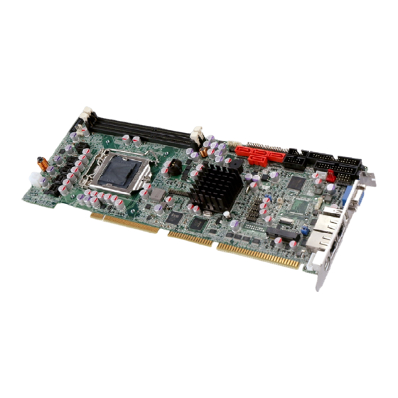
WSB-H610 PICMG 1.0 CPU Card 1.1 Introduction Figure 1-1: WSB-H610 The WSB-H610 PICMG 1.0 CPU card is a Socket LGA1155 32nm Intel® Core ™ i3/i5/i7/Pentium®/Celeron® processor platform that supports two 240-pin 1066/1333 MHz dual-channel DDR3/DDR3L DIMM modules up to 16.0 GB. -
Page 18: Model Variations
WSB-H610 PICMG 1.0 CPU Card 1.2 Model Variations The model variations of the WSB-H610 are listed below. Model No. CPU Supported DVI-D by 26-pin header WSB-H610-DVI-R10 LGA1155 Intel® Core™ i7/i5/i3/Pentium®/Celeron® LGA1155 Intel® Core™ WSB-H610-R10 i7/i5/i3/Pentium®/Celeron® Table 1-1: WSB-H610 Model Variations 1.3 Features... -
Page 19: Connectors
WSB-H610 PICMG 1.0 CPU Card 1.4 Connectors The connectors on the WSB-H610 are shown in the figure below. Figure 1-2: Connectors Page 4... -
Page 20: Dimensions
WSB-H610 PICMG 1.0 CPU Card 1.5 Dimensions The main dimensions of the WSB-H610 are shown in the diagram below. Figure 1-3: WSB-H610 Dimensions (mm) Page 5... -
Page 21: Figure 1-4: External Interface Panel Dimensions (Mm)
WSB-H610 PICMG 1.0 CPU Card Figure 1-4: External Interface Panel Dimensions (mm) Page 6... -
Page 22: Data Flow
WSB-H610 PICMG 1.0 CPU Card 1.6 Data Flow F igure 1-5 shows the data flow between the system chipset, the CPU and other components installed on the motherboard. Figure 1-5: Data Flow Diagram Page 7... -
Page 23: Technical Specifications
WSB-H610 PICMG 1.0 CPU Card 1.7 Technical Specifications The WSB-H610 technical specifications are listed below. Specification/Model WSB-H610 PICMG 1.0 Form Factor LGA1155 Intel® Core™ i7/i5/i3/Pentium®/Celeron® CPU CPU Supported Intel® H61 Memory Two 240-pin 1333/1066 MHz dual-channel unbuffered DDR3/DDR3L (1.35V) SDRAM DIMMs support (system max. 16.0 GB) Graphics Engine Intel®... -
Page 24: Table 1-2: Wsb-H610 Specifications
WSB-H610 PICMG 1.0 CPU Card Specification/Model WSB-H610 One 14-pin header (power LED, HDD LED, speaker, power button, Front Panel reset button) One 4-pin wafer connector Infrared One via 5-pin header Keyboard/Mouse One PS/2 keyboard/mouse port One 6-pin wafer connector Parallel Port... -
Page 25: Packing List
WSB-H610 PICMG 1.0 CPU Card Chapter Packing List Page 10... -
Page 26: Anti-Static Precautions
Only handle the edges of the PCB: Don't touch the surface of the motherboard. Hold the motherboard by the edges when handling. 2.2 Unpacking Precautions When the WSB-H610 is unpacked, please do the following: Follow the antistatic guidelines above. Make sure the packing box is facing upwards when opening. -
Page 27: Packing List
If any of the components listed in the checklist below are missing, do not proceed with the installation. Contact the IEI reseller or vendor the WSB-H610 was purchased from or contact an IEI sales representative directly by sending an email to ales@ieiworld.com. -
Page 28: Optional Items
WSB-H610 PICMG 1.0 CPU Card Quantity Item and Part Number Image DVI-D/USB kit (DVI model only) (P/N: IO-KIT-001-R20) One Key Recovery CD Utility CD Quick Installation Guide Table 2-1: Packing List 2.4 Optional Items The following are optional components which may be separately purchased:... - Page 29 WSB-H610 PICMG 1.0 CPU Card Item and Part Number Image FDD flat cable (P/N: 32200-000017-RS) LPT cable (P/N: 19800-000049-RS) 7.1-channel HD audio kit with Realtek ALC892 audio codec supporting dual audio stream (P/N: AC-KIT-892HD-R10) 20-pin Infineon TPM module (P/N: TPM-IN01-R11)
-
Page 30: Table 2-2: Optional Items
WSB-H610 PICMG 1.0 CPU Card Item and Part Number Image Intel® Core™ i5-2500T processor (LGA1155, quad core 2.3 GHz, 6M cache, 45W, compatible with CF-1156C-RS CPU cooler kit) (P/N: CPU-DT-i5-2500T) Intel® Core™ i5-2390T processor (LGA1155, dual core 2.7 GHz, 3M cache, 35W, compatible with CF-1156C-RS... -
Page 31: Connectors
WSB-H610 PICMG 1.0 CPU Card Chapter Connectors Page 16... -
Page 32: Peripheral Interface Connectors
WSB-H610 PICMG 1.0 CPU Card 3.1 Peripheral Interface Connectors This chapter details all the jumpers and connectors. 3.1.1 WSB-H610 Layout The figures below show all the connectors and jumpers. Figure 3-1: Connectors and Jumpers 3.1.2 Peripheral Interface Connectors The table below lists all the connectors on the board. -
Page 33: External Interface Panel Connectors
WSB-H610 PICMG 1.0 CPU Card Connector Type Label DVI-D connector (DVI model only) 26-pin header DVI1 EC SPI flash connector 6-pin wafer JSPI2 Fan connector (CPU) 4-pin wafer CPU_FAN1 Floppy disk drive connector 34-pin box header FDD1 Front panel connector... -
Page 34: Internal Peripheral Connectors
CN Pinouts: See Table 3-3 The ATX power supply enable connector enables the WSB-H610 to be connected to an ATX power supply. To enable an ATX power supply, the AT/ATX Power Select jumper must also be configured. Please refer to Chapter 4 for more details. -
Page 35: Audio Kit Connector
WSB-H610 PICMG 1.0 CPU Card 3.2.2 Audio Kit Connector CN Label: J_AUDIO1 10-pin header CN Type: CN Location: See Figure 3-3 CN Pinouts: See Table 3-4 This connector connects to an external audio kit. Figure 3-3: Audio Connector Location Description... -
Page 36: Battery Connector
WSB-H610 PICMG 1.0 CPU Card 3.2.3 Battery Connector CAUTION: Risk of explosion if battery is replaced by an incorrect type. Only certified engineers should replace the on-board battery. Dispose of used batteries according to instructions and local regulations. CN Label:... -
Page 37: Cpu Power Input Connector
WSB-H610 PICMG 1.0 CPU Card 3.2.4 CPU Power Input Connector CN Label: CPU12V1 4-pin Molex power connector CN Type: CN Location: See Figure 3-5 CN Pinouts: See Table 3-6 The connector supports the 12V power supply. Figure 3-5: ATX Power Connector Pinout Location... -
Page 38: Digital I/O Connector
WSB-H610 PICMG 1.0 CPU Card Figure 3-6: DDR3 DIMM Slot Locations 3.2.6 Digital I/O Connector CN Label: DIO1 CN Type: 10-pin header CN Location: See Figure 3-7 See Table 3-7 CN Pinouts: The digital I/O connector provides programmable input and output for external devices. -
Page 39: Dvi-D Connector (Dvi Model Only)
WSB-H610 PICMG 1.0 CPU Card Description Description Input 3 Input 2 Input 1 Input 0 Table 3-7: Digital I/O Connector Pinouts 3.2.7 DVI-D Connector (DVI Model Only) CN Label: DVI1 CN Type: 26-pin header CN Location: See Figure 3-8 CN Pinouts:... -
Page 40: Ec Spi Flash Connector
WSB-H610 PICMG 1.0 CPU Card Description Description CK_DVI_DATA1 CK_DVI_CLK# CK_DVI_CLK Table 3-8: DVI-D Connector Pinouts 3.2.8 EC SPI Flash Connector CN Label: JSPI2 6-pin wafer CN Type: CN Location: See Figure 3-9 CN Pinouts: See Table 3-9 The EC SPI flash connector is for flashing new BIOS onto the embedded controller. -
Page 41: Fan Connector (Cpu)
WSB-H610 PICMG 1.0 CPU Card 3.2.9 Fan Connector (CPU) CN Label: CPU_FAN1 4-pin wafer CN Type: CN Location: See Figure 3-10 CN Pinouts: See Table 3-10 The fan connector attaches to a CPU cooling fan. Figure 3-10: CPU Fan Connector Location... -
Page 42: Figure 3-11: Floppy Disk Connector Location
WSB-H610 PICMG 1.0 CPU Card Figure 3-11: Floppy Disk Connector Location Description Description DENSEL INDEX- MOTEA- DRVA- DIR- STEP- WDATA- WGATE- TK00- WPT- RDATA- SIDE1- DSKCHG- Table 3-11: Floppy Disk Connector Pinouts Page 27... -
Page 43: Front Panel Connector
WSB-H610 PICMG 1.0 CPU Card 3.2.11 Front Panel Connector CN Label: F_PANEL1 14-pin header CN Type: CN Location: See Figure 3-12 CN Pinouts: See Table 3-12 The front panel connector connects to the indicator LEDs and buttons on the computer's front panel. -
Page 44: I2C Connector
WSB-H610 PICMG 1.0 CPU Card 3.2.12 I2C Connector CN Label: I2C_1 4-pin wafer CN Type: CN Location: See Figure 3-13 CN Pinouts: See Table 3-13 The I2C connector is for system debug. Figure 3-13: I2C Connector Location Description +5VS PCH_GP38_PU... -
Page 45: Keyboard/Mouse Connector
WSB-H610 PICMG 1.0 CPU Card Figure 3-14: Infrared Connector Location Description IR-RX IR-TX Table 3-14: Infrared Connector Pinouts 3.2.14 Keyboard/Mouse Connector CN Label: KB_MS1 CN Type: 6-pin wafer See Figure 3-15 CN Location: CN Pinouts: See Table 3-15 The keyboard/mouse connector connects to a PS/2 Y-cable that can be connected to a PS/2 keyboard and mouse. -
Page 46: Parallel Port Connector
WSB-H610 PICMG 1.0 CPU Card Description +5 VCC Mouse Data Mouse Clock Keyboard Data Keyboard Clock GROUND Table 3-15: Keyboard/Mouse Connector Pinouts 3.2.15 Parallel Port Connector CN Label: LPT1 CN Type: 26-pin box header CN Location: See Figure 3-16 CN Pinouts:... -
Page 47: Pcie Mini Card Slot
WSB-H610 PICMG 1.0 CPU Card Description Description PPD3 PPD4 PPD5 PPD6 PPD7 BUSY SLCT Table 3-16: Parallel Port Connector Pinouts 3.2.16 PCIe Mini Card Slot CN Label: CN Type: PCIe Mini card slot CN Location: F igure 3-17 See Table 3-17 CN Pinouts: The PCIe Mini card slot is for installing a PCIe Mini expansion card. -
Page 48: Sata 3Gb/S Drive Connectors
WSB-H610 PICMG 1.0 CPU Card Description Description CLKREQ# LFRAME# LAD3 CLK- LAD2 CLK+ LAD1 LAD0 PCIRST# VCC3 PCIRST# PERN2 3VDual PERP2 1.5V SMBCLK PETN2 SMBDATA PETP2 USBD- USBD+ RF_LINK# BLUELED# 1.5V VCC3 Table 3-17: PCIe Mini Card Slot Pinouts 3.2.17 SATA 3Gb/s Drive Connectors... -
Page 49: Serial Port Connectors, Rs-232
WSB-H610 PICMG 1.0 CPU Card The SATA drive connectors can be connected to SATA drives and support up to 3Gb/s data transfer rate. Figure 3-18: SATA 3Gb/s Drive Connector Location Description Description Table 3-18: SATA 3Gb/s Drive Connector Pinouts 3.2.18 Serial Port Connectors, RS-232... -
Page 50: Serial Port Connector, Rs-422/485
WSB-H610 PICMG 1.0 CPU Card Figure 3-19: Serial Port Connector Location Description Description DCD# DSR# RTS# CTS# DTR# Table 3-19: Serial Port Connector Pinouts 3.2.19 Serial Port Connector, RS-422/485 CN Label: COM3 CN Type: 4-pin wafer CN Location: See Figure 3-20... -
Page 51: Smbus Connector
WSB-H610 PICMG 1.0 CPU Card Figure 3-20: RS-422/485 Connector Location Description Description RXD422- TXD422+/TXD485+ RXD422+ TXD422-/TXD485- Table 3-20: RS-422/485 Connector Pinouts Use the optional RS-422/485 cable to connect to a serial device. The pinouts of the DB-9 connector are listed below. -
Page 52: Spi Rom Connector
WSB-H610 PICMG 1.0 CPU Card Figure 3-21: SMBus Connector Location Description +5VS SMB_CLK SMB_DATA Table 3-22: SMBus Connector Pinouts 3.2.21 SPI ROM Connector CN Label: JSPI1 8-pin header CN Type: CN Location: See Figure 3-22 CN Pinouts: See Table 3-23 The SPI ROM connector is used to flash new BIOS onto the SPI BIOS chip. -
Page 53: Tpm Connector
WSB-H610 PICMG 1.0 CPU Card Description Description SPI_VCC SPI_CS0 SPI_CLK SPI_MISO SPI_MOSI Table 3-23: SPI ROM Connector Pinouts 3.2.22 TPM Connector CN Label: TPM1 20-pin header CN Type: CN Location: See Figure 3-23 CN Pinouts: See Table 3-24 The TPM connector connects to a TPM module. -
Page 54: Usb Connectors
WSB-H610 PICMG 1.0 CPU Card Description Description SB3V SERIRQ PM_SUS_STAT# DRQ# Table 3-24: TPM Connector Pinouts 3.2.23 USB Connectors CN Label: USB1, USB2, USB3 CN Type: 8-pin header CN Location: See Figure 3-24 CN Pinouts: See Table 3-25 The USB connectors connect to USB devices. Each pin header provides two USB ports. -
Page 55: External Peripheral Interface Connector Panel
RJ-45 CN Location: See Figure 3-25 CN Pinouts: See Figure 3-26 and Table 3-26 The WSB-H610 is equipped with two built-in RJ-45 Ethernet controllers. Each controller can connect to the LAN through one RJ-45 LAN connector. Description Description MDIA3- MDIA2+... -
Page 56: Keyboard/Mouse Connector
WSB-H610 PICMG 1.0 CPU Card Description Description on: linked off: 10 Mb/s blinking: data is being sent/received green: 100 Mb/s orange: 1000 Mb/s Table 3-27: Connector LEDs 3.3.2 Keyboard/Mouse Connector CN Label: KB_MS2 CN Type: PS/2 CN Location: See Figure 3-25... -
Page 57: Usb Connector
USB port CN Type: CN Location: See Figure 3-25 CN Pinouts: See Table 3-29 The WSB-H610 has one external USB 2.0 port. The port connects to both USB 2.0 and USB 1.1 devices. Description DATA- DATA+ GROUND Table 3-29: USB Port Pinouts 3.3.4 VGA Connector... -
Page 58: Figure 3-28: Vga Connector
WSB-H610 PICMG 1.0 CPU Card Description Description HSYNC VSYNC DDCCLK Table 3-30: VGA Connector Pinouts Figure 3-28: VGA Connector Page 43... -
Page 59: Installation
WSB-H610 PICMG 1.0 CPU Card Chapter Installation Page 44... -
Page 60: Anti-Static Precautions
Electrostatic discharge (ESD) can cause serious damage to electronic components, including the WSB-H610. Dry climates are especially susceptible to ESD. It is therefore critical that whenever the WSB-H610 or any other electrical component is handled, the following anti-static precautions are strictly adhered to. - Page 61 This helps to prevent potential ESD damage. Turn all power to the WSB-H610 off: When working with the WSB-H610, make sure that it is disconnected from all power supplies and that no electricity is being fed into the system.
-
Page 62: Socket Lga1155 Cpu Installation
WSB-H610 PICMG 1.0 CPU Card 4.2.1 Socket LGA1155 CPU Installation WARNING: CPUs are expensive and sensitive components. When installing the CPU please be careful not to damage it in anyway. Make sure the CPU is installed properly and ensure the correct cooling kit is properly installed. -
Page 63: Figure 4-2: Remove Protective Cover
WSB-H610 PICMG 1.0 CPU Card Figure 4-2: Remove Protective Cover Step 3: Inspect the CPU socket. Make sure there are no bent pins and make sure the socket contacts are free of foreign material. If any debris is found, remove it with compressed air. -
Page 64: Figure 4-3: Insert The Socket Lga1155 Cpu
WSB-H610 PICMG 1.0 CPU Card Figure 4-3: Insert the Socket LGA1155 CPU Step 8: Close the CPU socket. Close the load plate and pull the load lever back a little to have the load plate be able to secure to the knob. Engage the load lever by pushing it back to its original position (Figure 4-4). -
Page 65: Socket Lga1155 Cooling Kit Installation
WSB-H610 PICMG 1.0 CPU Card 4.2.2 Socket LGA1155 Cooling Kit Installation The cooling kit can be bought from IEI. The cooling kit has a heatsink and fan. WARNING: Do not wipe off (accidentally or otherwise) the pre-sprayed layer of thermal paste on the bottom of the heat sink. The thermal paste between the CPU and the heat sink is important for optimum heat dissipation. -
Page 66: Dimm Installation
WSB-H610 PICMG 1.0 CPU Card Step 5: Connect the fan cable. Connect the cooling kit fan cable to the fan connector on the WSB-H610. Carefully route the cable and avoid heat generating chips and fan blades. 4.2.3 DIMM Installation To install a DIMM, please follow the steps below and refer to Figure 4-6. -
Page 67: Jumper Settings
WSB-H610 PICMG 1.0 CPU Card 4.3 Jumper Settings NOTE: A jumper is a metal bridge used to close an electrical circuit. It consists of two or three metal pins and a small metal clip (often protected by a plastic cover) that slides over the pins to connect them. -
Page 68: Clear Cmos Jumper
WSB-H610 PICMG 1.0 CPU Card Setting Description Short 1-2 Use ATX power (Default) Short 2-3 Use AT power Table 4-2: AT/ATX Power Mode Jumper Settings Figure 4-7: AT/ATX Power Mode Jumper Location 4.3.2 Clear CMOS Jumper Jumper Label: J_CMOS1 Jumper Type:... -
Page 69: Wake-On Lan Jumper
WSB-H610 PICMG 1.0 CPU Card 4.3.3 Wake-on LAN Jumper CN Label: JLAN_PWR1 6-pin header CN Type: CN Location: See Figure 4-9 CN Pinouts: See Table 4-4 The Wake-on LAN jumper allows the user to enable or disable the Wake-on LAN (WOL) function. -
Page 70: Chassis Installation
The WSB-H610 must be installed in a chassis with ventilation holes on the sides allowing airflow to travel through the heat sink surface. In a system with an individual power supply unit, the cooling fan of a power supply can also help generate airflow through the board surface. -
Page 71: Dvi-D/Usb Kit Installation (Dvi Model Only)
4.5.2 DVI-D/USB Kit Installation (DVI Model Only) The DVI-D/USB kit, consisting of one DVI-D and four USB ports, connects to the DVI-D and USB connectors on the WSB-H610. To install the DVI-D/USB kit, please follow the steps below. Step 1: Connect the cables to the DVI-D/USB kit. -
Page 72: Sata Drive Connection
DVI-D/USB kit bracket to the system chassis. 4.5.3 SATA Drive Connection The WSB-H610 is shipped with four SATA drive cables. To connect the SATA drives to the connectors, please follow the steps below. Step 1: Locate the connectors. -
Page 73: Figure 4-12: Sata Drive Cable Connection
WSB-H610 PICMG 1.0 CPU Card Figure 4-12: SATA Drive Cable Connection Step 3: Connect the cable to the SATA disk. Connect the connector on the other end of the cable to the connector at the back of the SATA drive. See Figure 4-13. -
Page 74: Usb Cable (Dual Port) With Slot Bracket
WSB-H610 PICMG 1.0 CPU Card Figure 4-13: SATA Power Drive Connection 4.5.4 USB Cable (Dual Port) with Slot Bracket The WSB-H610 is shipped with a dual port USB 2.0 cable. To connect the USB cable connector, please follow the steps below. Step 1: Locate the connectors. -
Page 75: Pcie Mini Card Installation
Step 3: Insert the cable connectors. Once the cable connectors are properly aligned with the USB connectors on the WSB-H610, connect the cable connectors to the on-board connectors. See Figure 4-14. Figure 4-14: Dual USB Cable Connection Step 4: Attach the bracket to the chassis. The USB 2.0 connectors are attached to a bracket. -
Page 76: External Peripheral Interface Connection
4.6 External Peripheral Interface Connection This section describes connecting devices to the external connectors on the WSB-H610. 4.6.1 LAN Connection There are two external RJ-45 LAN connectors. The RJ-45 connectors enable connection to an external network. -
Page 77: Usb Device Connection (Single Connector)
RJ-45 connector into the on-board RJ-45 connector. 4.6.2 USB Device Connection (Single Connector) There is one external USB 2.0 connector. The connector is perpendicular to the WSB-H610. To connect a USB 2.0 or USB 1.1 device, please follow the instructions below. Step 1: Located the USB connector. -
Page 78: Vga Monitor Connection
4.6.3 VGA Monitor Connection The WSB-H610 has a single female DB-15 connector on the external peripheral interface panel. The DB-15 connector is connected to a CRT or VGA monitor. To connect a monitor to the WSB-H610, please follow the instructions below. -
Page 79: Figure 4-18: Vga Connector
WSB-H610 PICMG 1.0 CPU Card Figure 4-18: VGA Connector Step 4: Secure the connector. Secure the DB-15 VGA connector from the VGA monitor to the external interface by tightening the two retention screws on either side of the connector. Page 64... -
Page 80: Bios
WSB-H610 PICMG 1.0 CPU Card Chapter BIOS Page 65... -
Page 81: Introduction
WSB-H610 PICMG 1.0 CPU Card 5.1 Introduction The BIOS is programmed onto the BIOS chip. The BIOS setup program allows changes to certain system settings. This chapter outlines the options that can be changed. NOTE: Some of the BIOS options may vary throughout the life cycle of the product and are subject to change without prior notice. -
Page 82: Getting Help
WSB-H610 PICMG 1.0 CPU Card Function Decrease the numeric value or make changes Page Up key Increase the numeric value or make changes Page Dn key Decrease the numeric value or make changes Esc key Main Menu – Quit and not save changes into CMOS... -
Page 83: Main
WSB-H610 PICMG 1.0 CPU Card Save & Exit – Selects exit options and loads default settings The following sections completely describe the configuration options found in the menu items at the top of the BIOS screen and listed above. 5.2 Main The Main BIOS menu (BIOS Menu 1) appears when the BIOS Setup program is entered. -
Page 84: Advanced
WSB-H610 PICMG 1.0 CPU Card Memory Information The Memory Information lists a brief summary of the on-board memory. The fields in Memory Information cannot be changed. Total Memory: Displays the auto-detected system memory size and type. The System Overview field also has two user configurable fields: System Date [xx/xx/xx] Use the System Date option to set the system date. -
Page 85: Acpi Settings
WSB-H610 PICMG 1.0 CPU Card Aptio Setup Utility – Copyright (C) 2011 American Megatrends, Inc. Main Advanced Chipset Boot Security Save & Exit > ACPI Settings System ACPI Parameters > Trusted Computing > CPU Configuration > SATA Configuration > Intel TXT(LT) Configuration ---------------------- >... -
Page 86: Trusted Computing
WSB-H610 PICMG 1.0 CPU Card ACPI Sleep State [S1 (CPU Stop Clock)] Use the ACPI Sleep State option to specify the sleep state the system enters when it is not being used. (CPU Stop The system enters S1 (POS) sleep state. The... -
Page 87: Cpu Configuration
WSB-H610 PICMG 1.0 CPU Card TPM Support [Disable] Use the TPM Support option to configure support for the TPM. TPM support is disabled. Disable EFAULT Enable TPM support is enabled. 5.3.3 CPU Configuration Use the CPU Configuration menu (BIOS Menu 5) to enter the CPU Information submenu or enable Intel Virtualization Technology. -
Page 88: Cpu Information
WSB-H610 PICMG 1.0 CPU Card 5.3.3.1 CPU Information Use the CPU Information submenu (BIOS Menu 6) to view detailed CPU specifications and configure the CPU. Aptio Setup Utility – Copyright (C) 2011 American Megatrends, Inc. Advanced CPU Information Intel(R) Core(TM) i5-2400 CPU 0 @ 3.10GHz... -
Page 89: Sata Configuration
WSB-H610 PICMG 1.0 CPU Card L2 Cache: Lists the amount of storage space on the L2 cache. L3 Cache: Lists the amount of storage space on the L3 cache. 5.3.4 SATA Configuration Use the SATA Configuration menu (BIOS Menu 7) to change and/or set the configuration of the SATA devices installed in the system. -
Page 90: Intel Txt(Lt) Configuration
WSB-H610 PICMG 1.0 CPU Card storage devices. Some legacy OS do not support this mode. Compatible Configures the on-board ATA controller to be in EFAULT compatible mode. In this mode, a SATA channel will replace one of the IDE channels. This mode supports up to 4 storage devices. -
Page 91: Usb Configuration
WSB-H610 PICMG 1.0 CPU Card 5.3.6 USB Configuration Use the USB Configuration menu (BIOS Menu 9) to read USB configuration information and configure the USB settings. Aptio Setup Utility – Copyright (C) 2011 American Megatrends, Inc. Advanced USB Configuration Enables Legacy USB support. -
Page 92: Super Io Configuration
WSB-H610 PICMG 1.0 CPU Card Enabled Legacy USB support enabled EFAULT Legacy USB support disabled Disabled Auto Legacy USB support is disabled if no USB devices are connected. 5.3.7 Super IO Configuration Use the Super IO Configuration menu (BIOS Menu 10) to set or change the configurations for the FDD controllers, parallel ports and serial ports. -
Page 93: Floppy Disk Controller Configuration
WSB-H610 PICMG 1.0 CPU Card 5.3.7.1 Floppy Disk Controller Configuration Use the Floppy Disk Controller Configuration menu (BIOS Menu 12) to configure the floppy disk controller. Aptio Setup Utility – Copyright (C) 2011 American Megatrends, Inc. Advanced Floppy Disk Controller Configuration... -
Page 94: Bios Menu 12: Serial Port N Configuration Menu
WSB-H610 PICMG 1.0 CPU Card Aptio Setup Utility – Copyright (C) 2011 American Megatrends, Inc. Advanced Serial Port n Configuration Enable or Disable Serial Port (COM) Serial Port [Enabled] Device Settings IO=3F8h; IRQ=4 --------------------- Change Settings [Auto] : Select Screen ↑... - Page 95 WSB-H610 PICMG 1.0 CPU Card IO=2F8h; Serial Port I/O port address is 2F8h and the interrupt IRQ=3, 4 address is IRQ3, 4 Serial Port I/O port address is 2C0h and the interrupt IO=2C0h; address is IRQ3, 4 IRQ=3, 4 IO=2C8h;...
- Page 96 WSB-H610 PICMG 1.0 CPU Card 5.3.7.2.3 Serial Port 3 Configuration Serial Port [Enabled] Use the Serial Port option to enable or disable the serial port. Disabled Disable the serial port Enable the serial port Enabled EFAULT Change Settings [Auto] Use the Change Settings option to change the serial port IO port address and interrupt address.
- Page 97 WSB-H610 PICMG 1.0 CPU Card 5.3.7.2.4 IrDA Configuration Serial Port [Enabled] Use the Serial Port option to enable or disable the serial port. Disabled Disable the serial port Enable the serial port Enabled EFAULT Change Settings [Auto] Use the Change Settings option to change the serial port IO port address and interrupt address.
-
Page 98: Parallel Port Configuration
WSB-H610 PICMG 1.0 CPU Card 5.3.7.3 Parallel Port Configuration Use the Parallel Port Configuration menu (BIOS Menu 12) to configure the serial port n. Aptio Setup Utility – Copyright (C) 2010 American Megatrends, Inc. Advanced Parallel Port Configuration Enable or Disable... -
Page 99: H/W Monitor
WSB-H610 PICMG 1.0 CPU Card IO=278h; Parallel Port I/O port address is 278h and the IRQ=7 interrupt address is IRQ7 Parallel Port I/O port address is 3BCh and the IO=3BCh; interrupt address is IRQ7 IRQ=7 Device Mode [Printer Mode] Use the Device Mode option to select the mode the parallel port operates in. -
Page 100: Bios Menu 14: H/W Monitor
WSB-H610 PICMG 1.0 CPU Card Aptio Setup Utility – Copyright (C) 2011 American Megatrends, Inc. Advanced PC Health Status Smart FAN Configuration CPU Temperature :+52 C Accuracy: 1.(-5~+10) degree around 100 degree 2.(-10~+15) degree around 50 degree SYS Temperature :+34 C... -
Page 101: Cpu_Fan 1 Configuration
WSB-H610 PICMG 1.0 CPU Card 5.3.8.1 CPU_FAN 1 Configuration Use the CPU_FAN 1 Configuration submenu (BIOS Menu 15) to configure fan 1 temperature and speed settings. Aptio Setup Utility – Copyright (C) 2011 American Megatrends, Inc. Advanced Smart Fan Mode Configuration... -
Page 102: Serial Port Console Redirection
WSB-H610 PICMG 1.0 CPU Card 5.3.9 Serial Port Console Redirection The Serial Port Console Redirection menu (BIOS Menu 16) allows the console redirection options to be configured. Console redirection allows users to maintain a system remotely by re-directing keyboard input and text output through the serial port. - Page 103 WSB-H610 PICMG 1.0 CPU Card Bits per second [115200] Use the Bits per second option to specify the serial port transmission speed. The speed must match the other side. Long or noisy lines may require lower speeds. 9600 Sets the serial port transmission speed at 9600.
-
Page 104: Iei Feature
WSB-H610 PICMG 1.0 CPU Card Stop Bits [1] Use the Stop Bits option to specify the number of stop bits used to indicate the end of a serial data packet. Communication with slow devices may require more than 1 stop bit. -
Page 105: Chipset
WSB-H610 PICMG 1.0 CPU Card Aptio Setup Utility – Copyright (C) 2011 American Megatrends, Inc. Advanced iEi Feature Auto Recovery Function Reboot and recover Auto Recovery Function [Disabled] system automatically within 10 min, when OS crashes. Please install Auto Recovery API service before enabling this function. -
Page 106: Northbridge Configuration
WSB-H610 PICMG 1.0 CPU Card Aptio Setup Utility – Copyright (C) 2011 American Megatrends, Inc. Main Advanced Chipset Boot Security Save & Exit > North Bridge North Bridge Parameters > South Bridge > Integrated Graphics --------------------- : Select Screen ↑ ↓: Select Item Enter Select +/-: Change Opt. - Page 107 WSB-H610 PICMG 1.0 CPU Card of PCI graphics controller, a PCI express (PEG) controller or an IGD. Configuration options are listed below: PEG/IGD/PCI EFAULT IGD Memory [64M] Use the IGD Memory option to specify the amount of system memory that can be used by the internal graphics device.
- Page 108 WSB-H610 PICMG 1.0 CPU Card 416M 416 MB of memory used by internal graphics device 448 MB of memory used by internal graphics 448M device 480M 480 MB of memory used by internal graphics device 512M 512 MB of memory used by internal graphics...
-
Page 109: Southbridge Configuration
WSB-H610 PICMG 1.0 CPU Card 5.4.2 Southbridge Configuration Use the South Bridge menu (BIOS Menu 20) to configure the Southbridge chipset. Aptio Setup Utility – Copyright (C) 2011 American Megatrends, Inc. Chipset SouthBridge Configuration Specify what state to go to when power is... -
Page 110: Integrated Graphics
WSB-H610 PICMG 1.0 CPU Card 5.4.3 Integrated Graphics Use the Integrated Graphics menu (BIOS Menu 21) to configure the video device connected to the system. Aptio Setup Utility – Copyright (C) 2011 American Megatrends, Inc. Advanced Intel IGD SWSCI OpRegion Configuration... -
Page 111: Boot
WSB-H610 PICMG 1.0 CPU Card DVMT Memory [Maximum] Use the DVMT Memory option to specify the maximum amount of memory that can be allocated as graphics memory. Configuration options are listed below. 128 MB 256 MB Maximum EFAULT IGD - Boot Type [AUTO] Use the IGD - Boot Type option to select the display device used by the system when it boots. - Page 112 WSB-H610 PICMG 1.0 CPU Card Bootup NumLock State [On] Use the Bootup NumLock State BIOS option to specify if the number lock setting must be modified during boot up. Allows the Number Lock on the keyboard to be EFAULT enabled automatically when the computer system boots up.
-
Page 113: Security
WSB-H610 PICMG 1.0 CPU Card Option ROM Messages [Force BIOS] Use the Option ROM Messages option to set the Option ROM display mode. Sets display mode to force BIOS. Force EFAULT BIOS Sets display mode to current. Keep Current 5.6 Security Use the Security menu (BIOS Menu 23) to set system and user passwords. -
Page 114: Exit
WSB-H610 PICMG 1.0 CPU Card 5.7 Exit Use the Exit menu (BIOS Menu 24) to load default BIOS values, optimal failsafe values and to save configuration changes. Aptio Setup Utility – Copyright (C) 2011 American Megatrends, Inc. Main Advanced Chipset... - Page 115 WSB-H610 PICMG 1.0 CPU Card Save as User Defaults Use the Save as User Defaults option to save the changes done so far as user defaults. Restore User Defaults Use the Restore User Defaults option to restore the user defaults to all the setup options.
-
Page 116: Software Drivers
WSB-H610 PICMG 1.0 CPU Card Chapter Software Drivers Page 101... -
Page 117: Available Software Drivers
Intel® IT Director application Installation instructions are given below. 6.2 Software Installation All the drivers for the WSB-H610 are on the CD that came with the system. To install the drivers, please follow the steps below. Step 1: Insert the CD into a CD drive connected to the system. -
Page 118: Figure 6-1: Introduction Screen
WSB-H610 PICMG 1.0 CPU Card Figure 6-1: Introduction Screen Step 3: Click WSB-H610. Step 4: A new screen with a list of available drivers appears (Figure 6-2). Figure 6-2: Available Drivers Page 103... -
Page 119: Chipset Driver Installation
WSB-H610 PICMG 1.0 CPU Card Step 5: Install all of the necessary drivers in this menu. 6.3 Chipset Driver Installation To install the chipset driver, please do the following. Step 1: Access the driver list. (See Section 6.2) Step 2: Click “Chipset”. -
Page 120: Figure 6-4: Chipset Driver Welcome Screen
WSB-H610 PICMG 1.0 CPU Card Figure 6-4: Chipset Driver Welcome Screen Step 7: The license agreement in Figure 6-5 appears. Step 8: Read the License Agreement. Step 9: Click Yes to continue. Figure 6-5: Chipset Driver License Agreement Step 10: The Read Me file in Figure 6-6 appears. -
Page 121: Figure 6-6: Chipset Driver Read Me File
WSB-H610 PICMG 1.0 CPU Card Step 11: Click Next to continue. Figure 6-6: Chipset Driver Read Me File Step 12: Setup Operations are performed as shown in Figure 6-7. Step 13: Once the Setup Operations are complete, click Next to continue. -
Page 122: Graphics Driver Installation
WSB-H610 PICMG 1.0 CPU Card Step 14: The Finish screen in Figure 6-8 appears. Step 15: Select “Yes, I want to restart this computer now” and click Finish. Figure 6-8: Chipset Driver Installation Finish Screen 6.4 Graphics Driver Installation To install the Graphics driver, please do the following. -
Page 123: Figure 6-9: Graphics Driver Welcome Screen
WSB-H610 PICMG 1.0 CPU Card Figure 6-9: Graphics Driver Welcome Screen Step 6: The License Agreement in Figure 6-10 appears. Step 7: Click Yes to accept the agreement and continue. Figure 6-10: Graphics Driver License Agreement Step 8: Setup Operations are performed as shown in Figure 6-11. -
Page 124: Figure 6-11: Graphics Driver Setup Operations
WSB-H610 PICMG 1.0 CPU Card Step 9: Once the Setup Operations are complete, click Next to continue. Figure 6-11: Graphics Driver Setup Operations Step 10: The Finish screen in Figure 6-12 appears. Step 11: Select “Yes, I want to restart this computer now” and click Finish. -
Page 125: Lan Driver Installation
WSB-H610 PICMG 1.0 CPU Card 6.5 LAN Driver Installation To install the LAN driver, please do the following. Step 1: Access the driver list. (See Section 6.2) Step 2: Click “LAN”. Step 3: Locate the Autorun file and double click it. -
Page 126: Figure 6-14: Lan Driver Installation
WSB-H610 PICMG 1.0 CPU Card Figure 6-14: LAN Driver Installation Step 8: The program begins to install. Step 9: When the driver installation is complete, the screen in Figure 6-15 appears. Step 10: Click Finish to exit. Figure 6-15: LAN Driver Installation Complete... -
Page 127: Audio Driver Installation
WSB-H610 PICMG 1.0 CPU Card 6.6 Audio Driver Installation To install the audio driver, please do the following. Step 1: Access the driver list. (See Section 6.2) Step 2: Click “Audio” and select the folder which corresponds to the operating system. -
Page 128: Figure 6-17: Audio Driver Installation Welcome Screen
WSB-H610 PICMG 1.0 CPU Card Figure 6-17: Audio Driver Installation Welcome Screen Step 7: The driver installation begins. See Figure 6-18. Figure 6-18: Audio Driver Installation Step 8: When the driver is installed, the driver installation finish screen in Figure 6-19 appears. -
Page 129: Abios Options
WSB-H610 PICMG 1.0 CPU Card Appendix BIOS Options Page 114... - Page 130 WSB-H610 PICMG 1.0 CPU Card Below is a list of BIOS configuration options in the BIOS chapter. System Overview .........................68 Memory Information ......................69 System Date [xx/xx/xx] ......................69 System Time [xx:xx:xx] .......................69 ACPI Sleep State [S1 (CPU Stop Clock)] ................71 ...
- Page 131 WSB-H610 PICMG 1.0 CPU Card Stop Bits [1] ..........................89 Flow Control [None]......................89 Auto Recovery Function [Disabled]...................90 Initiate Graphic Adapter [PEG/IGD/PCI]................91 IGD Memory [64M] .......................92 PEG Force Gen1 [Enabled] ....................93 Detect Non-Compliance Device [Enabled] ................93 ...
-
Page 132: B One Key Recovery
WSB-H610 PICMG 1.0 CPU Card Appendix One Key Recovery Page 117... -
Page 133: One Key Recovery Introduction
WSB-H610 PICMG 1.0 CPU Card B.1 One Key Recovery Introduction The IEI one key recovery is an easy-to-use front end for the Norton Ghost system backup and recovery tool. This tool provides quick and easy shortcuts for creating a backup and reverting to that backup or reverting to the factory default settings. -
Page 134: System Requirement
WSB-H610 PICMG 1.0 CPU Card After completing the five initial setup procedures as described above, users can access the recovery tool by pressing <F3> while booting up the system. The detailed information of each function is described in Section B.5. -
Page 135: Supported Operating System
WSB-H610 PICMG 1.0 CPU Card partitions. Please take the following table as a reference when calculating the size of the partition. OS Image after Ghost Compression Ratio Windows® 7 7 GB 5 GB Windows® XPE 776 MB 560 MB Windows® CE 6.0... -
Page 136: Setup Procedure For Windows
WSB-H610 PICMG 1.0 CPU Card Linux Fedora Core 12 (Constantine) Fedora Core 11 (Leonidas) Fedora Core 10 (Cambridge) Fedora Core 8 (Werewolf) Fedora Core 7 (Moonshine) RedHat RHEL-5.4 RedHat 9 (Ghirke) Ubuntu 8.10 (Intrepid) Ubuntu 7.10 (Gutsy) Ubuntu 6.10 (Edgy) Debian 5.0 (Lenny) -
Page 137: Hardware And Bios Setup
WSB-H610 PICMG 1.0 CPU Card The detailed descriptions are described in the following sections. NOTE: The setup procedures described below are for Microsoft Windows operating system users. For Linux, most of the setup procedures are the same except for several steps described in Section B .3. -
Page 138: Figure B-2: Launching The Recovery Tool
WSB-H610 PICMG 1.0 CPU Card Step 2: Boot the system from recovery CD. When prompted, press any key to boot from the recovery CD. It will take a while to launch the recovery tool. Please be patient! Figure B-2: Launching the Recovery Tool Step 3: The recovery tool setup menu is shown as below. -
Page 139: Figure B-4: Command Mode
WSB-H610 PICMG 1.0 CPU Card Figure B-4: Command Mode Step 5: The command prompt window appears. Type the following commands (marked in red) to create two partitions. One is for the OS installation; the other is for saving recovery files and images which will be an invisible partition. -
Page 140: Figure B-5: Partition Creation Commands
WSB-H610 PICMG 1.0 CPU Card Figure B-5: Partition Creation Commands Page 125... -
Page 141: Install Operating System, Drivers And Applications
WSB-H610 PICMG 1.0 CPU Card NOTE: Use the following commands to check if the partitions were created successfully. Step 6: Press any key to exit the recovery tool and automatically reboot the system. Please continue to the following procedure: Build the Recovery Partition.S t e p 0 :... -
Page 142: Build-Up Recovery Partition
WSB-H610 PICMG 1.0 CPU Card B.2.4 Build-up Recovery Partition Step 1: Put the recover CD in the optical drive. Step 2: Start the system. Step 3: Boot the system from the recovery CD. When prompted, press any key to boot from the recovery CD. It will take a while to launch the recovery tool. Please... -
Page 143: Figure B-8: Building The Recovery Partition
WSB-H610 PICMG 1.0 CPU Card Step 5: The Symantec Ghost window appears and starts configuring the system to build a recovery partition. In this process the partition created for recovery files in Section B .2.2 is hidden and the recovery tool is saved in this partition. -
Page 144: Create Factory Default Image
WSB-H610 PICMG 1.0 CPU Card B.2.5 Create Factory Default Image NOTE: Before creating the factory default image, please configure the system to a factory default environment, including driver and application installations. To create a factory default image, please follow the steps below. -
Page 145: Figure B-12: About Symantec Ghost Window
WSB-H610 PICMG 1.0 CPU Card Figure B-12: About Symantec Ghost Window Step 4: Use mouse to navigate to the option shown below ( F igure B-13). Figure B-13: Symantec Ghost Path Step 5: Select the local source drive (Drive 1) as shown in F igure B-14. -
Page 146: Figure B-14: Select A Local Source Drive
WSB-H610 PICMG 1.0 CPU Card Figure B-14: Select a Local Source Drive Step 6: Select a source partition (Part 1) from basic drive as shown in F igure B-15. Then click OK. Figure B-15: Select a Source Partition from Basic Drive Step 7: Select 1.2: [Recovery] NTFS drive and enter a file name called... -
Page 147: Figure B-16: File Name To Copy Image To
WSB-H610 PICMG 1.0 CPU Card Figure B-16: File Name to Copy Image to Step 8: When the Compress Image screen in F igure B-17 prompts, click High to make the image file smaller. Figure B-17: Compress Image Page 132... -
Page 148: Figure B-18: Image Creation Confirmation
WSB-H610 PICMG 1.0 CPU Card Step 9: The Proceed with partition image creation window appears, click Yes to continue. Figure B-18: Image Creation Confirmation Step 10: The Symantec Ghost starts to create the factory default image ( F igure B-19). -
Page 149: Auto Recovery Setup Procedure
WSB-H610 PICMG 1.0 CPU Card Step 12: The recovery tool main menu window is shown as below. Press any key to reboot the system. S t e p 0 : Figure B-21: Press Any Key to Continue B.3 Auto Recovery Setup Procedure... -
Page 150: Figure B-22: Auto Recovery Utility
WSB-H610 PICMG 1.0 CPU Card Step 1: Follow the steps described in Section B.2.1 ~ Section B.2.3 to setup BIOS, create partitions and install operating system. Step 2: Install the auto recovery utility into the system by double clicking the Utility/AUTORECOVERY-SETUP.exe in the One Key Recovery CD. -
Page 151: Figure B-24: Launching The Recovery Tool
WSB-H610 PICMG 1.0 CPU Card Step 4: Reboot the system from the recovery CD. When prompted, press any key to boot from the recovery CD. It will take a while to launch the recovery tool. Please be patient! Figure B-24: Launching the Recovery Tool Step 5: When the recovery tool setup menu appears, press <4>... -
Page 152: Figure B-26: Building The Auto Recovery Partition
WSB-H610 PICMG 1.0 CPU Card Figure B-26: Building the Auto Recovery Partition Step 7: After completing the system configuration, the following message prompts to confirm whether to create a factory default image. Type Y to have the system create a factory default image automatically. Type N within 6 seconds to skip this process (The default option is YES). -
Page 153: Figure B-28: Image Creation Complete
WSB-H610 PICMG 1.0 CPU Card Step 8: The Symantec Ghost starts to create the factory default image (Figure B-28). Figure B-28: Image Creation Complete Step 9: After completing the system configuration, press any key in the following window to restart the system. -
Page 154: Setup Procedure For Linux
WSB-H610 PICMG 1.0 CPU Card BIOS SETUP UTILITY Main Advanced PCIPNP Boot Security Chipset Exit iEi Feature ⎯⎯⎯⎯⎯⎯⎯⎯⎯⎯⎯⎯⎯⎯⎯⎯⎯⎯⎯⎯⎯⎯⎯⎯⎯⎯⎯ Auto Recovery Function [Enabled] Recover from PXE [Disabled] Select Screen ↑ ↓ Select Item Enter Go to SubScreen General Help Save and Exit Exit v02.61 ©Copyright 1985-2006, American Megatrends, Inc. -
Page 155: Figure B-30: Partitions For Linux
WSB-H610 PICMG 1.0 CPU Card Partition 1: / Partition 2: SWAP NOTE: Please reserve enough space for partition 3 for saving recovery images. Figure B-30: Partitions for Linux Step 3: Create a recovery partition. Insert the recovery CD into the optical disk drive. -
Page 156: Figure B-31: System Configuration For Linux
WSB-H610 PICMG 1.0 CPU Card recovery partition. After completing the system configuration, press any key to reboot the system. Eject the recovery CD. Figure B-31: System Configuration for Linux Step 5: Access the recovery tool main menu by modifying the “menu.lst”. To first access the recovery tool main menu, the menu.lst must be modified. -
Page 157: Recovery Tool Functions
WSB-H610 PICMG 1.0 CPU Card Step 7: The recovery tool menu appears. ( F igure B-33) Figure B-33: Recovery Tool Menu Step 8: Create a factory default image. Follow Step 2 Step 12 described in Section B .2.5 to create a factory default image. -
Page 158: Figure B-34: Recovery Tool Main Menu
WSB-H610 PICMG 1.0 CPU Card Figure B-34: Recovery Tool Main Menu The recovery tool has several functions including: 1. Factory Restore: Restore the factory default image (iei.GHO) created in Section B .2.5. 2. Backup system: Create a system backup image (iei_user.GHO) which will be saved in the hidden partition. -
Page 159: Factory Restore
WSB-H610 PICMG 1.0 CPU Card B.5.1 Factory Restore To restore the factory default image, please follow the steps below. Step 1: Type <1> and press <Enter> in the main menu. Step 2: The Symantec Ghost window appears and starts to restore the factory default. A factory default image called iei.GHO is created in the hidden Recovery partition. -
Page 160: Backup System
WSB-H610 PICMG 1.0 CPU Card B.5.2 Backup System To backup the system, please follow the steps below. Step 1: Type <2> and press <Enter> in the main menu. Step 2: The Symantec Ghost window appears and starts to backup the system. A backup image called iei_user.GHO is created in the hidden Recovery partition. -
Page 161: Restore Your Last Backup
WSB-H610 PICMG 1.0 CPU Card B.5.3 Restore Your Last Backup To restore the last system backup, please follow the steps below. Step 1: Type <3> and press <Enter> in the main menu. Step 2: The Symantec Ghost window appears and starts to restore the last backup image (iei_user.GHO). -
Page 162: Manual
WSB-H610 PICMG 1.0 CPU Card B.5.4 Manual To restore the last system backup, please follow the steps below. Step 1: Type <4> and press <Enter> in the main menu. Step 2: The Symantec Ghost window appears. Use the Ghost program to backup or recover the system manually. -
Page 163: Restore Systems From A Linux Server Through Lan
WSB-H610 PICMG 1.0 CPU Card B.6 Restore Systems from a Linux Server through LAN The One Key Recovery allows a client system to automatically restore to a factory default image saved in a Linux system (the server) through LAN connectivity after encountering a Blue Screen of Death (BSoD) or a hang for around 10 minutes. -
Page 164: Configure Dhcp Server Settings
WSB-H610 PICMG 1.0 CPU Card B.6.1 Configure DHCP Server Settings Step 1: Install the DHCP #yum install dhcp (CentOS, commands marked in red) #apt-get install dhcp3-server (Debian, commands marked in blue) Step 2: Confirm the operating system default settings: dhcpd.conf. -
Page 165: Configure Tftp Settings
WSB-H610 PICMG 1.0 CPU Card filename “pxelinux.0”; B.6.2 Configure TFTP Settings Step 1: Install the tftp, httpd and syslinux. #yum install tftp-server httpd syslinux (CentOS) #apt-get install tftpd-hpa xinetd syslinux (Debian) Step 2: Enable the TFTP server by editing the “/etc/xinetd.d/tftp” file and make it use the remap file. -
Page 166: Configure One Key Recovery Server Settings
WSB-H610 PICMG 1.0 CPU Card Debian Replace the TFTP settings from “inetd” to “xinetd” and annotate the “inetd” by adding “#”. #vi /etc/inetd.conf Modify: #tftp dgram udp wait root /usr/sbin..(as shown below) #vi /etc/xinetd.d/tftp B.6.3 Configure One Key Recovery Server Settings Step 1: Copy the Utility/RECOVERYR10.TAR.BZ2 package from the One Key... -
Page 167: Start The Dhcp, Tftp And Http
WSB-H610 PICMG 1.0 CPU Card B.6.4 Start the DHCP, TFTP and HTTP Start the DHCP, TFTP and HTTP. For example: CentOS #service xinetd restart #service httpd restart #service dhcpd restart Debian #/etc/init.d/xinetd reload #/etc/init.d/xinetd restart #/etc/init.d/dhcp3-server restart B.6.5 Create Shared Directory Step 1: Install the samba. -
Page 168: Setup A Client System For Auto Recovery
WSB-H610 PICMG 1.0 CPU Card Modify: [image] comment = One Key Recovery path = /share/image browseable = yes writable = yes public = yes create mask = 0644 directory mask = 0755 Step 4: Edit “/etc/samba/smb.conf” for your environment. For example:... -
Page 169: Figure B-42: Disable Automatically Restart
WSB-H610 PICMG 1.0 CPU Card Figure B-42: Disable Automatically Restart Step 2: Configure the following BIOS options of the client system. Advanced → iEi Feature → Auto Recovery Function → Enabled Advanced → iEi Feature → Recover from PXE → Enabled Boot →... - Page 170 WSB-H610 PICMG 1.0 CPU Card MUST be installed in the system, otherwise, the system will automatically restore from the factory default image every ten (10) minutes. Step 6: Restart the client system from LAN. If the system encounters a Blue Screen of Death (BSoD) or a hang for around 10 minutes, it will automatically restore from the factory default image.
-
Page 171: Other Information
WSB-H610 PICMG 1.0 CPU Card NOTE: A firewall or a SELinux is not in use in the whole setup process described above. If there is a firewall or a SELinux protecting the system, modify the configuration information to accommodate them. - Page 172 WSB-H610 PICMG 1.0 CPU Card Step 5: When the following window appears, press <S> to select “Specify Additional Device”. Page 157...
-
Page 173: System Memory Requirement
WSB-H610 PICMG 1.0 CPU Card Step 6: In the following window, select a SATA controller mode used in the system. Then press <Enter>. The user can now start using the SATA HDD. Step 7: After pressing <Enter>, the system will get into the recovery tool setup menu. -
Page 174: C Terminology
WSB-H610 PICMG 1.0 CPU Card Appendix Terminology Page 159... - Page 175 WSB-H610 PICMG 1.0 CPU Card AC ’97 Audio Codec 97 (AC’97) refers to a codec standard developed by Intel® in 1997. ACPI Advanced Configuration and Power Interface (ACPI) is an OS-directed configuration, power management, and thermal management interface. AHCI Advanced Host Controller Interface (AHCI) is a SATA Host controller register-level interface.
- Page 176 WSB-H610 PICMG 1.0 CPU Card DIMM Dual Inline Memory Modules are a type of RAM that offer a 64-bit data bus and have separate electrical contacts on each side of the module. The digital inputs and digital outputs are general control signals that control the on/off circuit of external devices or TTL devices.
- Page 177 WSB-H610 PICMG 1.0 CPU Card LVDS Low-voltage differential signaling (LVDS) is a dual-wire, high-speed differential electrical signaling system commonly used to connect LCD displays to a computer. POST The Power-on Self Test (POST) is the pre-boot actions the system performs when the system is turned-on.
-
Page 178: D Digital I/O Interface
WSB-H610 PICMG 1.0 CPU Card Appendix Digital I/O Interface Page 163... -
Page 179: Introduction
WSB-H610 PICMG 1.0 CPU Card D.1 Introduction The DIO connector on the WSB-H610 is interfaced to GPIO ports on the Super I/O chipset. The DIO has both 4-bit digital inputs and 4-bit digital outputs. The digital inputs and digital outputs are generally control signals that control the on/off circuit of external devices or TTL devices. -
Page 180: Enable The Dio Output Function
WSB-H610 PICMG 1.0 CPU Card D.3.2 Enable the DIO Output Function The BIOS interrupt call INT 15H controls the digital I/O. An assembly program to enable digital I/O output functions is listed below. AX, 6F09H Sets the digital port as output... -
Page 181: E Watchdog Timer
WSB-H610 PICMG 1.0 CPU Card Appendix Watchdog Timer Page 166... - Page 182 WSB-H610 PICMG 1.0 CPU Card NOTE: The following discussion applies to DOS environment. Contact IEI support or visit the IEI website for specific drivers for other operating systems. The Watchdog Timer is provided to ensure that standalone systems can always recover from catastrophic conditions that cause the CPU to crash.
- Page 183 WSB-H610 PICMG 1.0 CPU Card NOTE: When exiting a program it is necessary to disable the Watchdog Timer, otherwise the system resets. EXAMPLE PROGRAM: ; INITIAL TIMER PERIOD COUNTER W_LOOP: AX, 6F02H ;setting the time-out value BL, 30 ;time-out value is 48 seconds ;...
-
Page 184: F Hazardous Materials Disclosure
WSB-H610 PICMG 1.0 CPU Card Appendix Hazardous Materials Disclosure Page 169... -
Page 185: Hazardous Materials Disclosure Table For Ipb Products Certified As Rohs Compliant Under 2002/95/Ec Without Mercury
WSB-H610 PICMG 1.0 CPU Card F.1 Hazardous Materials Disclosure Table for IPB Products Certified as RoHS Compliant Under 2002/95/EC Without Mercury The details provided in this appendix are to ensure that the product is compliant with the Peoples Republic of China (China) RoHS standards. The table below acknowledges the presences of small quantities of certain materials in the product, and is applicable to China RoHS only. - Page 186 WSB-H610 PICMG 1.0 CPU Card Part Name Toxic or Hazardous Substances and Elements Lead Mercury Cadmium Hexavalent Polybrominated Polybrominated Biphenyls Diphenyl (Pb) (Hg) (Cd) Chromium (CR(VI)) (PBB) Ethers (PBDE) Housing Display Printed Circuit Board Metal Fasteners Cable Assembly Fan Assembly...
- Page 187 WSB-H610 PICMG 1.0 CPU Card 此附件旨在确保本产品符合中国 RoHS 标准。以下表格标示此产品中某有毒物质的含量符 合中国 RoHS 标准规定的限量要求。 本产品上会附有”环境友好使用期限”的标签,此期限是估算这些物质”不会有泄漏或突变”的 年限。本产品可能包含有较短的环境友好使用期限的可替换元件,像是电池或灯管,这些元 件将会单独标示出来。 部件名称 有毒有害物质或元素 铅 汞 镉 六价铬 多溴联苯 多溴二苯 醚 (Pb) (Hg) (Cd) (CR(VI)) (PBB) (PBDE) 壳体 显示 印刷电路板 金属螺帽 电缆组装 风扇组装 电力供应组装 电池 O: 表示该有毒有害物质在该部件所有物质材料中的含量均在 SJ/T11363-2006 标准规定的限量要求以下。...
Need help?
Do you have a question about the WSB-H610 and is the answer not in the manual?
Questions and answers