Table of Contents
Advertisement
Quick Links
Operating & Installation Instructions
Translation of the Original Assembly Instructions EN
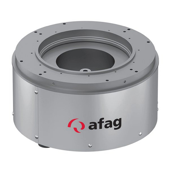
WV 630-1 (Right)
WV 630-1 (Left)
WV 630-1 (Right)
WV 630-1 (Left)
Operating & Installation Instructions EN
Bowl feeder
WV630-1
230 V / 50 Hz
Order no.: 50455916
230 V / 50 Hz
Order no.: 50470026
115 V / 60 Hz
Order no.: 50508376
115 V / 60 Hz
Order no.: 50508383
WV630-1
Date 08.11.2023
Version 2.0
1–40
Advertisement
Table of Contents

Subscribe to Our Youtube Channel
Related Manuals for Afag WV630-1


Summary of Contents for Afag WV630-1
- Page 1 Operating & Installation Instructions Bowl feeder WV630-1 Translation of the Original Assembly Instructions EN WV 630-1 (Right) 230 V / 50 Hz Order no.: 50455916 WV 630-1 (Left) 230 V / 50 Hz Order no.: 50470026 ...
- Page 2 Your Afag team © Subject to modifications The bowl feeders have been designed by Afag Automation AG according to the state of the art. Due to the constant technical development and improvement of our products, we reserve the right to make technical changes at any time.
-
Page 3: Table Of Contents
Scope of supply ..................17 Transport ....................18 Packaging ....................18 Storage ....................... 18 Design and description ..................19 Structure of the WV630-1 ................19 Description of the WV630-1 ............... 20 Operating & Installation Instructions EN WV630-1 Date 08.11.2023 Version 2.0 3–40... - Page 4 9.4.1 Spare parts ................... 38 9.4.2 Wear parts .................... 38 Decommissioning and disposal ................. 39 10.1 Safety instructions ..................39 10.2 Decommissioning ..................39 10.3 Disposal ...................... 39 WV630-1 4 – 40 Operating & Installation Instructions EN Date 08.11.2023 Version 2.0 ...
-
Page 5: General
NOTICE This safety note points out a potentially dangerous situation which, if not avoided, can cause substantial damage to property and the environment. Operating & Installation Instructions EN WV630-1 Date 08.11.2023 Version 2.0 5–40 ... -
Page 6: Additional Symbols
In these assembly instructions the following symbols are used to highlight instructions, results, references, etc.. Symbol Description Instructions (steps ...) Results of actions References to sections Enumerations not ordered WV630-1 6 – 40 Operating & Installation Instructions EN Date 08.11.2023 Version 2.0 ... -
Page 7: Warranty
This does also apply to defective accessories and wear parts. Normal wear and tear are excluded from the warranty. The warranty covers the replacement or repair of defective Afag parts. Further claims are excluded. The warranty shall expire in the following cases: ... -
Page 8: Safety Instructions
Failure to follow the directions and safety instructions given in this instructions manual may result in serious hazards. Intended use The Afag bowl feeders WV are exclusively designed for storing, conveying, separating and sorting workpieces of different dimensions, design forms and material variants. -
Page 9: Foreseeable Misuse
observe and communicate universally applicable laws and regulations regarding accident prevention and environmental protection, provide the necessary personal protective equipment (e.g. protective gloves) and instruct the personnel to wear it. Operating & Installation Instructions EN WV630-1 Date 08.11.2023 Version 2.0 9–40 ... -
Page 10: Obligations Of The Personnel
Operator (trained personnel): Authorized persons who due to their specialized professional training, expertise and experience are capable of identifying risks and preventing possible hazards arising from the use of the machine. WV630-1 10 – 40 Operating & Installation Instructions EN Date 08.11.2023 Version 2.0... -
Page 11: Personal Protective Equipment (Ppe)
6.6 "Device-specific adjustment". Afag Automation AG accepts no liability for unauthorised changes or improper assembly, installation, commissioning, maintenance or repair work. The bowl feeders may not be changed or modified in any way, except with the prior written consent of Afag. -
Page 12: Danger Due To Electricity
Limbs can be crushed by moving components! Work on and with the WV may only be carried out by qualified personnel. Never reach into the system during normal operation! WV630-1 12 – 40 Operating & Installation Instructions EN Date 08.11.2023... -
Page 13: Danger Due To Alternating Magnetic Fields
The alternating magnetic fields occurring in the immediate vicinity of the WV can affect the proper functioning of e.g. pacemakers and defibrillators. Persons with a pacemaker must keep a safety distance of at least 10 cm from the WV630-1 (distance implant to field source). 2.8.5 Noise hazards... -
Page 14: Technical Data
Technical data Technical data Dimensional drawing WV630 -1 Fig. 1 Dimensional drawing WV630-1 WV630-1 14 – 40 Operating & Installation Instructions EN Date 08.11.2023 Version 2.0 ... -
Page 15: Technical Data Drawing Wv630 -1
Technical data 3.2 Technical data drawing WV630 -1 Operating & Installation Instructions EN WV630-1 Date 08.11.2023 Version 2.0 15–40 ... -
Page 16: Accessories
SMART 115V/60Hz 50528967 external setpoint input RTS 15A For more information on the controller, see chap. 6.5 and the controller manufacturer's instructions. WV630-1 16 – 40 Operating & Installation Instructions EN Date 08.11.2023 Version 2.0 ... -
Page 17: Transport, Packaging And Storage
The corresponding documentation is supplied with each bowl feeder (e.g. operating and installation instructions, etc.). Fig. 2 Scope of delivery WV [Unt] Designation Bowl feeder WV Operating & Installation Instructions HAN Q5/0 Connector Operating & Installation Instructions EN WV630-1 Date 08.11.2023 Version 2.0 17–40 ... -
Page 18: Transport
Relative air humidity: < 90%, non condensing Packaging The bowl feeder is transported in the Afag Automation AG transport packaging. If no Afag packaging is used, the bowl feeder must be packed in such a way that it is protected against shocks and dust. NOTICE... -
Page 19: Design And Description
The transport movement is generated by vibration. Here, the parts are moved in the transport direction by micro-jumps. The bowl feeders are to be operated in combination with an Afag controller. Only in this combination can optimum conveying behaviour be guaranteed. -
Page 20: Description Of The Wv630-1
Design and description Description of the WV630-1 Fig. 4 Bowl feeder basic structure 1. Conveyed material α Jumping-off angle 2. Conveyor track β. Inclination of leaf springs 3. Leaf spring γ. Pitch angle of the spiral 4. Jumping-off direction The magnet, connected to the support, creates a force which attracts reps. -
Page 21: Installation, Assembly And Setting
Observe the safety instructions in chap. 2 "Safety instructions" of this manual as well as the instructions in chap. 6.5. Operating & Installation Instructions EN WV630-1 Date 08.11.2023 Version 2.0 21–40 ... -
Page 22: Preparatory Activities For Assembly
For the bowl feeder, the feed directions are defined as follows: Right-hand (R), in clockwise direction Left-hand (L), in anti-clockwise direction Fig. 5 Defined feed direction WV630-1 22 – 40 Operating & Installation Instructions EN Date 08.11.2023 Version 2.0 ... -
Page 23: Fixing Bowl Feeder
WV with base plate and mounting foot WV with base plate and levelling foot Fig. 6 Fastening of the bowl feeder When mounting, make sure that the base is horizontal. Operating & Installation Instructions EN WV630-1 Date 08.11.2023 Version 2.0 23–40 ... -
Page 24: Fastening To The Drive
Fitting holes are provided on the mounting plate through which the bowl can be precisely positioned on the WV drive. This eliminates the need to set up the interface on the bowl discharge again when changing the bowl. WV630-1 24 – 40 Operating & Installation Instructions EN Date 08.11.2023 Version 2.0... - Page 25 Installation, assembly and setting Fastening options on the drive: Radial fastening Fastening from above Fastening from below Fig. 8 Bowl attachment: radial, from above and on the circumference Operating & Installation Instructions EN WV630-1 Date 08.11.2023 Version 2.0 25–40 ...
-
Page 26: Mount The Feeding Bowl
Increasing the delivery rate by increasing the amplitude has an extremely negative effect on the system. Spring fractures or inadmissible heating of the solenoid coil can be the result. WV630-1 26 – 40 Operating & Installation Instructions EN Date 08.11.2023 Version 2.0 ... -
Page 27: Electric Connection (Controller)
All IRG types operate with smooth start and offer different options for mounting, attachment and control. A detailed description of the controller can be found in the Afag general catalogue. Third-party control units can also be used, provided they meet the technical conditions. -
Page 28: Adjustment Of The Oscillation System
5. Switch on the bowl feeder and set the controller to 90% (with SE position 8) 6. Slowly loosen the lower fastening screw (1) on one spring assembly. The speed of the material in the feeding bowl changes! WV630-1 28 – 40 Operating & Installation Instructions EN Date 08.11.2023... - Page 29 Unsteady running speed between two spring packs: 1. Viewed in the running direction behind the unsteady running speed, either install a spring or remove a spring. After completing the adjustment work, refit the housing! Operating & Installation Instructions EN WV630-1 Date 08.11.2023 Version 2.0 29–40 ...
-
Page 30: Commissioning And Operation
Pull out the mains plug before removing the housing! Work on the electrical equipment may only be carried out by trained, authorized personnel! WV630-1 30 – 40 Operating & Installation Instructions EN Date 08.11.2023 Version 2.0... -
Page 31: Preparatory Activities For Commissioning
The use of the operating software is described in the installation instructions for the controllers used. 2. If the module is supplied with an Afag controller, no further action is required (operating parameters already stored in the controller). 3. When using a different controller, special cables must be made and the operating parameters determined. -
Page 32: Fault Elimination
Fault causes and remedy Faults caused by defective components may only be remedied by replacing these components. Only Afag original spare and wear parts may be used! Fault Possible cause Remedy: Plug not connected to mains ... -
Page 33: Maintenance And Repair
Observe the operating instructions of the controller used! Also observe the safety instructions in chap. 2 „Safety instructions“ in this manual. Operating & Installation Instructions EN WV630-1 Date 08.11.2023 Version 2.0 33–40 ... -
Page 34: Maintenance Activities And Maintenance Intervals
- Loose connections, scorched or otherwise damaged cables - Replace damaged cables immediately! Feeding bowl Cleaning Regularly [Off] Clean the feeding bowl. Observe notes in chap. 9.3.2! WV630-1 34 – 40 Operating & Installation Instructions EN Date 08.11.2023 Version 2.0 ... -
Page 35: Notes On Cleaning The Feeding Bowl
Benzine or spirit not be poured into the feeding Nextel bowl. Feeding bowl must not be immersed in cleaning bath. Operating & Installation Instructions EN WV630-1 Date 08.11.2023 Version 2.0 35–40 ... -
Page 36: Remove Or Replace Leaf Springs
5. Check air gap between solenoid coil and yoke and readjust if necessary ( chap. 9.3.4 ). 6. Assembly the housing. 7. Perform test run. The process is completed. WV630-1 36 – 40 Operating & Installation Instructions EN Date 08.11.2023 Version 2.0 ... -
Page 37: Set Magnetic Gap
Otherwise the magnetic gap is too large and the adjustment process must be repeated. 7. Refit the cover. The process is completed. Operating & Installation Instructions EN WV630-1 Date 08.11.2023 Version 2.0 37–40 ... -
Page 38: Further Maintenance
AFAG for warranty repair within the warranty period. After expiry of the warranty period, the customer may replace or repair defective modules or wear parts himself or send them to the Afag repair service. Please note that Afag does not assume any warranty for modules that have not been replaced or repaired by Afag! 9.4.1... -
Page 39: 10 Decommissioning And Disposal
Electronic parts, electrical scrap, auxiliary and operating materials must be disposed of by approved specialist companies. Information on proper disposal can be obtained from the responsible local authorities. Operating & Installation Instructions EN WV630-1 Date 08.11.2023 Version 2.0 39–40 ... - Page 40 WV630-1 40 – 40 Operating & Installation Instructions EN Date 08.11.2023 Version 2.0 ...
Need help?
Do you have a question about the WV630-1 and is the answer not in the manual?
Questions and answers