Advertisement
Quick Links
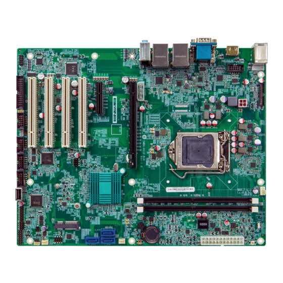
ATX motherboard supports 14nm LGA1151 6th generation Intel®
Core™ i7/i5/i3, Celeron® and Pentium® processor, DDR4,
dual independent display via VGA and HDMI, dual Intel® GbE LAN,
USB 3.1 Gen 1, SATA 6Gb/s, HD Audio and RoHS
Quick Installation Guide
Package List
IMBA-H112 package includes the following items:
1 x IMBA-H112 single board computer
1 x I/O shielding
2 x SATA cable
1 x QIG
IMBA-H112
Version 1.0
October 21, 2019.
©2019 Copyright by IEI Integration corp.
All rights reserved.
1
Advertisement

Related Manuals for IEI Technology IMBA-H112


Summary of Contents for IEI Technology IMBA-H112
- Page 1 USB 3.1 Gen 1, SATA 6Gb/s, HD Audio and RoHS IMBA-H112 Quick Installation Guide Version 1.0 October 21, 2019. Package List IMBA-H112 package includes the following items: 1 x IMBA-H112 single board computer 1 x I/O shielding 2 x SATA cable ...
-
Page 2: Specifications
Specifications CPU: LGA1151 socket supports 6th generation Intel® Core™ i7/i5/i3, Celeron® and Pentium® processor System Chipset: Intel® H110 Memory: Two 288-pin 2133MHz dual-channel DDR4 SDRAM un-buffered DIMM slots (system max. 64 GB) BIOS: AMI UEFI BIOS ... - Page 3 SIO: Fintek 81866D-I EC: IT8528E Audio: Realtek ALC662 HD Audio codec supports 5.1-channel (line-in, line-out, mic-in) Front Audio: 2x5-pin header Front Panel: 1 x Front panel (2x7 pin, power LED, HDD LED, speaker, power button, reset button) ...
-
Page 4: Ordering Information
All the drivers and One Key Recovery IEI Resource Download Center utility for the IMBA-H112 are available on https://download.ieiworld.com IEI Resource Download Center. Type IMBA-H112 and press Enter to find all the relevant software, utilities, and documentation. To install software from the downloaded ISO file, mount the file as a virtual drive to view its content. -
Page 5: Jumpers Setting And Connectors
Jumpers setting and connectors LABEL FUNCTION J_ATX_AT1 AT/ATX Power Mode Setting J_CMOS1 Clear CMOS Button USB SW1, USB SW2 USB Power Setting J_FLASH1 Flash Descriptor Security Override F_PANEL1 PWR & RST Buttons and Indicators COM1/VGA1 VGA and RS-232 Serial Port Connectors HDMI1 HDMI Connector Internal DisplayPort Connector... - Page 6 LED_LAN1 LAN1 Link LED Connector LED_LAN2 LAN2 Link LED Connector CHASSIS1 Chassis Status Connector LPT1 Parallel Port Connector J_ATX_AT1: AT/ATX Power Mode Setting PIN NO. DESCRIPTION Short 1 - 2 ATX Mode (default) Short 2 - 3 AT Mode J_CMOS1: Clear CMOS Button PIN NO.
- Page 7 J_FLASH1: Flash Descriptor Security Override PIN NO. DESCRIPTION Short 1 - 2 Disabled (default) Short 2 - 3 Enabled F_PANEL1: PWR & RST Buttons and Indicators DESCRIPTION DESCRIPTION BEEP_PWR SPKR IPMI ID_LED+ IPMI LED IPMI ID_LED- PWRBTN_SW# PC_BEEP SPKR EXTRST- RESET SATA_LED# COM1/VGA1: VGA and RS-232 Serial Port Connectors...
- Page 8 HDMI1: HDMI Connector PIN NO. DESCRIPTION PIN NO. DESCRIPTION HDMI_DATA2 HDMI_DATA2# HDMI_SCL HDMI_DATA1 HDMI_SDA HDMI_DATA1# HDMI_DATA0 HDMI_HPD HDMI_GND HDMI_DATA0# HDMI_GND HDMI_CLK HDMI_GND HDMI_GND HDMI_CLK# DP1 : Internal DisplayPort Connector PIN NO. DESCRIPTION PIN NO. DESCRIPTION AUXP LANE1N AUXN LANE1P LANE2P LANE3N LANE2N LANE3P...
- Page 9 LAN1_USB1: Ethernet and USB 3.1 Gen 1 Connectors USB1: External USB 3.1 Gen 1 Connectors PIN NO. DESCRIPTION PIN NO. DESCRIPTION USB_DATA- USB_DATA- USB_DATA+ USB_ DATA+ USB3_RX- USB3_RX- USB3_RX+ USB3_ RX+ USB3_TX- USB3_TX- USB3_TX+ USB3_TX+ LAN1: RJ-45 LAN Connector PIN NO. DESCRIPTION PIN NO.
- Page 10 LAN2_USB2: Ethernet and USB 3.1 Gen 1 Connectors USB2: External USB 3.1 Gen 1 Connectors PIN NO. DESCRIPTION PIN NO. DESCRIPTION USB_DATA- USB_DATA- USB_DATA+ USB_ DATA+ USB3_RX- USB3_RX- USB3_RX+ USB3_ RX+ USB3_TX- USB3_TX- USB3_TX+ USB3_TX+ LAN2: RJ-45 LAN Connector PIN NO. DESCRIPTION PIN NO.
- Page 11 USB2-3: Internal USB 2.0 Connector (Type A) PIN NO. DESCRIPTION PIN NO. DESCRIPTION DATA- DATA+ COM2~5: Internal RS-232 Serial Port Connectors PIN NO. DESCRIPTION PIN NO. DESCRIPTION COM6: Internal RS-232/422/485 Serial Port Connector PIN NO. DESCRIPTION PIN NO. DESCRIPTION...
- Page 12 AUDIO_CV1: HD Audio Connector PIN NO. DESCRIPTION Line_In CD/DVD or other audio source input port (Blue) Line_Out Connect this port to headphone or speaker (Green) Microphone Connect this port to microphone (Pink) FRONT-PANEL1: Front Panel Audio Connector PIN NO. DESCRIPTION PIN NO.
- Page 13 MPCIE1: mSATA Card Connector PIN NO. DESCRIPTION PIN NO. DESCRIPTION PCIE_WAKE# +3.3V 1.5V MSATA_CLK# MSATA _CLK PLTRST_N +3.3V PLTRST_N SATA_RX+ +3.3V SATA_RX- 1.5V SMB_CLK SATA_TX- SMB_DATA SATA_TX+ USB_DATA- USB_DATA+ +3.3V +3.3V +3.3V CLINK_CLK CLINK_DATA 1.5V CLINK_RST# MSATA_DET +3.3V...
- Page 14 PCIEx4_1: PCIe x4 Connector DESCRIPTION DESCRIPTION +V12S PCIEX8_PRSNT1_N_1 +V12S +V12S +V12S +V12S SMB_CLK_PCIE1 SMB_DATA_PCIE1 +V3P3S +V3P3S +V3P3A_PCIEAUX +V3P3S PLTRST_N CLK_PCIE_PCI_P EXP_A_TX_0_C_DP CLK_PCIE_PCI_N EXP_A_TX_0_C_DN PCIE_RXP1 PCIEX8_PRSNT1_N_1 PCIE_RXN1 EXP_A_TX_1_C_DP EXP_A_TX_1_C_DN PCIE_RXP2 PCIE_RXN2 EXP_A_TX_2_C_DP EXP_A_TX_2_C_DN PCIE_RXP3 PCIE_RXN3 EXP_A_TX_3_C_DP EXP_A_TX_2_C_DN PCIE_RXP4 PCIE_RXN4 PCIEX8_PRSNT1_N_1...
- Page 15 ATX1: 24-pin ATX Power Source Connector PIN NO. DESCRIPTION PIN NO. DESCRIPTION +3.3V +3.3V +3.3V -12V PS_ON Power good 5VSB +12V +12V +3.3V CPU12V1: +12V Power Source Connector PIN NO. DESCRIPTION PIN NO. DESCRIPTION +12V +12V ATXPWR1: PCIe Power Connector PIN NO.
- Page 16 CN1: EC Debug Port Connector PIN NO. DESCRIPTION PIN NO. DESCRIPTION EC_EPP_STB# EC_EPP_AFD# EC_EPP_PD0 EC_EPP_PD1 EC_EPP_INIT# EC_EPP_PD2 EC_EPP_SLIN# EC_EPP_PD3 EC_EPP_PD4 EC_EPP_PD5 EC_EPP_BUSY EC_EPP_PD6 EC_EPP_KSI5 EC_EPP_PD7 EC_EPP_KSI4 JSPI1: Flash SPI ROM Connector PIN NO. DESCRIPTION PIN NO. DESCRIPTION +3.3V SPI_CS# SPI_SO SPI_CLK SPI_SI JSPI2: Flash EC ROM Connector...
- Page 17 I2C1: I C Connector (to EC) PIN NO. DESCRIPTION PIN NO. DESCRIPTION PCH_GP38 PCH_GP39 LED_LAN1: LAN Link LED Connector DESCRIPTION DESCRIPTION +3.3V LAN1_LED_LNK#_ACT LED_LAN2: LAN Link LED Connector DESCRIPTION DESCRIPTION +3.3V LAN2_LED_LNK#_ACT CHASSIS1: Chassis Status Connector DESCRIPTION DESCRIPTION +VRTC CHASSIS OPEN LPT1 : Parallel Port Connector PIN NO.
- Page 18 Board Layout: Jumper and Connector Locations (Unit: mm)
Need help?
Do you have a question about the IMBA-H112 and is the answer not in the manual?
Questions and answers