Table of Contents
Advertisement
Quick Links
Advertisement
Table of Contents

Subscribe to Our Youtube Channel
Related Manuals for Fanvil i504

Summary of Contents for Fanvil i504
- Page 1 User Manual Version: 2.12 | Date: 2024.4.12...
-
Page 2: Table Of Contents
Directory Directory ............................1 1 Safety Instruction ........................6 1.1 Safety Instruction ......................6 1.2 FCC ........................... 7 2 Product Overview ........................9 2.1 Overview ...........................9 2.2 Specification Parameter ....................10 3 Installation Instructions ......................11 3.1 Device Inventory ......................11 3.2 Installation Procedure ....................11 3.2.1 Wall-mounted ......................11 4 User Guide ..........................14 4.1 Button and Interface Instructions ................ - Page 3 5.2 Answer Call ........................22 5.2.1 Answer Call ......................22 5.2.2 Auto Answer ......................22 5.3 Reject The Call ......................23 5.3.1 Manually Reject ....................23 5.3.2 DND ........................23 5.4 End The Call ........................23 5.5 Mute ..........................23 5.5.1 Mute The Call ....................... 24 5.5.2 Ringing Mute ......................24 5.6 Call Hold/Resume ......................
- Page 4 8.1 Video Preview ........................36 8.2 Monitor ..........................36 8.2.1 Manual Addition ....................37 8.2.2 Scan Addition ......................37 8.3 Video Linkage ........................38 9 Contacts ............................39 9.1 DoorPhone List ......................39 9.2 Local Phonebook ......................40 9.2.1 Add/ Edit / Delete Contact .................. 40 9.2.2 Add/ Edit / Delete Group ..................41 9.2.3 Browse/ Add /Delete Contacts In Group ............42 9.3 Cloud Phonebook ......................
- Page 5 12.2.4 Screen Saver ......................60 12.3 Audio Settings ......................60 12.3.1 Ring Setting ......................60 12.3.2 Volume Setting ....................61 12.3.3 Alert Info Ring Setting ..................61 12.3.4 Tone Setting ......................62 12.3.5 Upload Ring ......................63 12.4 Greeting Words Setting ..................... 63 13 Function Key Settings ......................
- Page 6 17 Trouble Shooting ........................87 17.1 Get Device System Information ................87 17.2 Reboot Device ......................87 17.3 Device Factory Reset ....................87 17.4 Screenshot ........................88 17.5 Network Packets Capture ..................88 17.6 Get Device Log ......................88 17.7 Common Trouble Cases ................... 89 18 Appendix Table ........................91 18.1 Appendix I - Function Icon ..................
-
Page 7: Safety Instruction
Safety Instruction 1.1 Safety Instruction Please read the following safety notices before installing or using this unit. They are crucial for the safe and reliable operation of the device. Please use the product-specified power adapter. If you need to use a power ... -
Page 8: Fcc
Do not install this phone in an ill-ventilated place. You are in a situation that could cause bodily injury. Before you work on any equipment, be aware of the hazards involved with electrical circuitry and be familiar with standard practices for preventing accidents. - Page 9 environment. This equipment should be installed and operated with minimum distance of 20cm between the radiator and your body. This transmitter must not be co-located or operating in conjunction with any other antenna or transmitter.
-
Page 10: Product Overview
In order to help some interested users to better understand the details of the product, the user manual can be used as a reference guide for the use of i504&i504W&i506W. This document may not apply to the latest version of the software. If you have any... -
Page 11: Specification Parameter
2.2 Specification Parameter Spec. i504 i504W i506W Material quality Screen 7” 1024*600 10” 1280*800 Wi-Fi 2.4G/5G 2.4G/5G Speaker 8×short-circuit input 1×doorbell input. Interface 1×short-circuit output 1×RS485 Network 10/100 Mbps adaptive Operating -10℃~50℃ temperature Size (LWH) 177.38x113.99x22.5mm Wall-mounted Support... -
Page 12: Installation Instructions
Installation Instructions 3.1 Device Inventory 3.2 Installation Procedure Wall-mounted 3.2.1 Wall-mount Bracket support: Chinese standard:86 Box American standard:Single cylinder lateral, Double cylinder European standard:80 bottom box Installation preparation: Step 1:Installation of the bracket There is no junction box on the wall. ... - Page 13 C. Secure the bracket to the wall with four TA4*30mm screws. D. Installation of the wall-mount bracket is complete. There is a junction box (86-type) on the wall. A. Secure the bracket to the 86 box with two PM4*16mm screws. B.
-
Page 15: User Guide
User Guide 4.1 Button and Interface Instructions Number Name Description Interface Power interface Power interface:12V/1A input ① WAN interface,standard RJ45 interface,10/100M adaptive,support Network interface ② POE input,it is recommended to use CAT5 or CAT5E network cable. 2-pin, 2.0mm pitch socket, 12V/1A Power interface ③-1 input. -
Page 16: Setup Guide
8 sets of alarm RS485 interface(Reserve) ③-5 input interfaces 4.2 Setup Guide After the device is powered on for the first time or restored to factory settings, a setup guide will appear. You can set the language, time zone, and network.After selecting the language and time zone in the setup guide interface, click [Next] to enter the network settings interface. -
Page 17: Touchscreen Instructions
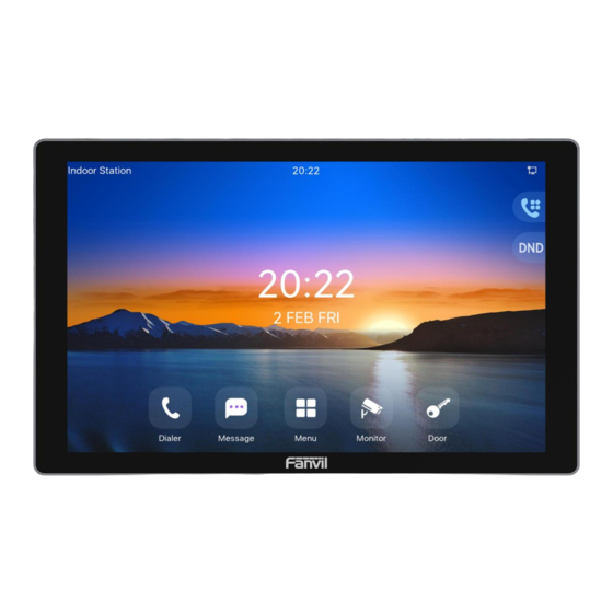
the status of the user interface for most of the time. The icon description is described in 18.1appendix Number Description Welcome word, number ① Time, Date ② Status icon ③ Function Key ④ ⑤ Common Functions ⑥ 4.5 Touchscreen Instructions Touch Method 4.5.1 Click:... -
Page 18: Touch Keyboard
Touch Keyboard 4.5.2 Users can input numbers or set functional parameters through the touchscreen keyboard in interfaces such as dialing and menu settings. It supports three types of keyboards: 1. Numeric keypad, supporting the input of numbers and special characters. 2. -
Page 19: Device Status
Display device call logs, including incoming, outgoing, missed, and Call Log call forwarding logs. Application Ping, QR code function. Access local device contacts, cloud phonebook, and access control PhoneBook lists to quickly search for contacts. Message View and send text messages. View and listen to voicemail messages. -
Page 20: Web Management
1. Connect the computer and the device to the same local network, and install Device Manager on the PC. (Device Manager download link: https://www.fanvil.com/service/doc/soft/tools/tools/ipscanner/index.html); 2. Open the IP scanning tool (Device Manager), click on the scan button to obtain the IP address of the device within the local network. -
Page 21: Line Settings
4.9 Line Settings The device supports six SIP accounts simultaneously, Users can switch between the six SIP accounts as needed. Users can register SIP accounts through the device menu and the web interface. Registering an account through the device menu: Users can register SIP account by navigating to [Menu] >>... -
Page 22: Call Features
Call Features 5.1 Making Calls Making Calls 5.1.1 Dialing method Users can dial a number in the following ways: Entering the number directly Selecting a phone number from phonebook contacts (Refer to 9.2Phonebook). Selecting a phone number from cloud phonebook contacts (Refer to 9.3 Cloud ... -
Page 23: Answer Call
5.2 Answer Call Answer Call 5.2.1 When the device is idle and there is an incoming call, the user can answer the call by pressing [Answer] . To reject an incoming call, the user can press [Reject] button on the interface. Auto Answer 5.2.2 After the device's auto-answer feature is enabled, it will automatically answer incoming... -
Page 24: Reject The Call
5.3 Reject The Call Manually Reject 5.3.1 When receiving an incoming call, you can press the [End] button to reject the call. The rejected call will be displayed in the missed call list in the call log. 5.3.2 Users can activate the "Do Not Disturb" (DND) feature on the device to reject incoming calls. -
Page 25: Mute The Call
mode automatically disables upon the call's termination. Mute The Call 5.5.1 Pressing the [mute] button during a call displays a blue mute icon on the call interface. Unmute the call:P ress the device's mute button again on the call interface. ... - Page 26 There are three types: Unconditional Call Forward – Forward any incoming call to the configured number. Call Forward Busy – When the user is busy, incoming calls will be forwarded to the configured number. Call Forward on No Answer – When user does not answer the incoming call after ...
-
Page 27: Advance Function
Advance Function 6.1 Intercom After activating the intercom mode, the device can automatically answer incoming calls in intercom mode. Initiate Intercom. 6.1.1 Under standby mode, enter the [Function Key] interface, then select the programmed number to make a call. To use the intercom function, you need to set the function key as a memory key for intercom operation. -
Page 28: Mcast
Configuration parameters: Parameter Description Enable Intercom When intercom is enabled, the device will accept the incoming call request with a SIP header of Alert-Info instruction to automatically answer the call after specific delay. Enable Intercom Enable mute mode during the intercom call Mute Enable Intercom If the incoming call is intercom call, the phone plays the intercom tone... -
Page 29: Hotspot
When enabled, play the prompt sound when receiving Multicast prompt Tone multicast. When enabled, the same port and channel can only be Enable Prio Chan connected. Channel 24 is the priority channel, higher than 1-23; channel 0 means not to use the channel. Regardless of which of the two multicast groups is called in Enable Page Priority first, the device will receive the higher priority multicast first. - Page 30 Parameters Description Enable Hotspot Enable or disable hotspot Selecting 'SIP Hotspot' indicates that this device exists as a SIP Mode Hotspot. Selecting 'Client' indicates that this device exists as a client." The monitoring type can be broadcast or multicast. If you want to restrict broadcast packets in the network, you can choose multicast.
-
Page 31: Hotspot Extension Management
and the other options are set in the same way as the hotspot. The device is the hotspot server, and the default extension is 0. The device ACTS as a client, and the extension number is increased from 1 (the extension number can be viewed through the [SIP hotspot] page of the webpage). -
Page 32: Sms
6.4.1 Send messages: Click on [Menu] >> [Messages] on the screen, then click to create new message. Select the line and fill in the recipient's information. After editing is complete, click to send. View SMS: On the screen, click [Menu] >> [Messages] >> [Inbox]. When a new message ... - Page 33 configuration. In the [MWI] interface, you can view the number of read and unread voice messages. Call the number of voice message , enter the PIN code when prompted, and listen to the voice messages according to the prompts.
-
Page 34: Open Door
Open Door The indoor station can operate the door access control system to open the door while in standby mode or during a call. 7.1 Open The Door Under Standby Open The Door Under Standby 7.1.1 In standby mode, users can click [Open Door] button on the desktop and then select the corresponding door access control to open the door. -
Page 35: Open The Door During A Call
7.2 Open the door during a call During a call, users can click the indoor unit's door open button to open the door. After clicking, the access control unit that is currently in conversation with the indoor unit will open the door. Open The Door During A Call 7.2.1 The operation steps for opening the door during a call are as follows:... - Page 36 as desired. Number/IP: Enter the access control unit's IP address or number. Use the IP address only when the access control unit and indoor unit use IP calling. Line: Auto. Password: Enter the remote door opening password for the access control unit. ...
-
Page 37: Video Preview
Video Preview 8.1 Video Preview The video preview function allows users to see the video from the access control or the IP camera linked to it before answering the call. There are two supported methods for the video preview function: Preview via SIP Video ... -
Page 38: Manual Addition
Click on the [Back] button in the top left corner to exit monitoring. Manual Addition 8.2.1 The steps to manually add a camera are as follows: Click the [Monitor] button on the desktop. Click in the bottom right corner. ... -
Page 39: Video Linkage
User: The username required for ONVIF authentication. Password: The password required for ONVIF authentication. Click in the top right corner to add. Note: The access control or camera being scanned must have ONVIF functionality enabled. If it's not enabled, it needs to be enabled before scanning and adding. 8.3 Video Linkage The indoor unit can display the video from the bound access control or IP camera during an incoming call or conversation. -
Page 40: Contacts
Contacts 9.1 DoorPhone List Device Interface Settings: Click on [Menu] >> [Phonebook] >> [Door Access List] to access the Access Control List interface. Here, you can add, delete, or modify the entry passwords for access control devices. You can also initiate video or voice calls from within the Access Control List. -
Page 41: Local Phonebook
9.2 Local Phonebook Users can save contact information in the phonebook and directly dial the contact's phone number from the phonebook. By default, the phonebook is empty but can be populated via the device interface or web interface. Users can manually add contacts or import them from call logs (or cloud phonebook) into the phonebook. -
Page 42: Add/ Edit / Delete Group
[Phonebook] >> [Local Contacts], and then clicking on the contact's avatar in the contact list. Editing contacts via the web interface: Via the web interface, go to [Phonebook] >> [Contacts] and click [Edit] to edit contact information. Delete Contacts: Deleting contacts via the device interface: Users can delete contacts by navigating to [Menu] >>... -
Page 43: Browse/ Add /Delete Contacts In Group
Editing a group: Click on a group to enter its interface, click the edit button make changes. The number in parentheses indicates the total number of contacts in that group. Setting up groups via the web interface: Access the web page >> [Phonebook] >> [Advanced] >> [Group List] to add, edit, and delete groups. -
Page 44: Configure Cloud Phonebook
downloading its contacts to the device each time it is accessed. However, the download time can take a few seconds, depending on the quality of the network connection at the time of use. Therefore, to save time waiting for downloads, it is recommended that users save important contact information from the cloud phonebook to the local device. -
Page 45: Allowed List
Device interface settings: There are multiple ways to add numbers to the call blocking list, including directly through [Menu] >> [Phonebook] >> [Blocked List]. From within the phonebook (both local and network), you can select any number to ... -
Page 46: Restricted Outgoning List
9.6 Restricted Outgoning List The device supports setting restrictions on dialing out certain numbers. If these numbers are entered on the dialing interface, the call will not be allowed, and the device will emit a prohibited call tone and display a pop-up notification. Users can set up restricted outgoing numbers via the web interface by navigating to [Phonebook] >>... -
Page 47: Call Log
10 Call Log Device interface for viewing call logs: Viewing: The device can store up to 1000 call records. Users can open the call log by pressing [Menu] >> [Call Log] to view all incoming, outgoing, forwarded, and missed call records. In the call log screen interface, users can scroll to browse through the call logs. -
Page 48: Device Settings
11 Device Settings 11.1 Time Plan The Time Plan feature allows users to set specific actions to occur at either a particular time or within a period. A time point triggers an action at a specific moment, while a period triggers an action during a specified duration. Users can access this functionality through the web page under [Device Settings] >>... -
Page 49: Action Plan
Action Plan application: a technical implementation defined and designed by Fanvil for remote control and behavior linkage between Fanvil terminal equipment and other equipment. That is, when an event occurson the Fanvil terminal, the terminal can perform an action, and this action is completed according to a Plan rule. -
Page 50: Maintenance
User Agent Set user agent information 11.3 Maintenance Configurations 11.3.1 On this page, users with administrator privileges can view, export, or import the phone configuration, or restore the phone to factory Settings. Export Configurations Right click to select target save as, that is, to download the device's configuration file, suffix “.txt”... - Page 51 Online Upgrade 11.3.2.2 Through online upgrading, devices can be upgraded. Configuration for online upgrades by an administrator through a web page: Access the web page [System] >> [Upgrade] >> [Upgrade Server], configure the upgrade server, and the update cycle, etc. Place the upgrade TXT file and software on the corresponding server.
-
Page 52: Auto Provision
information version, the and version information in txt will be displayed under the new version description information. Instructions: After completing the configuration on the Manager web page, place the version information TXT file into the configured HTTP server. The naming format for the version information TXT file should be: vendor_model_hwv1_0.txt The TXT file must be in UTF-8 format, and the content format should be as follows: ... - Page 53 are enabled, the priority from high to low as below: PNP>DHCP>TR069> Static Provisioning Transferring protocol: FTP、 TFTP、 HTTP、 HTTPS Parameters: Parameters Description Basic Settings CPE Serial Number Display the device SN Configure the user name of FTP server; TFTP protocol does not need to be configured;...
- Page 54 Display Provision The Settings of the upgrade pop-up are displayed Prompt Normal: Automatic deployment has a high priority Provision config priority Manual: The priority set manually is high DHCP Option Setting Configure DHCP option, DHCP option supports DHCP Custom Option Value custom option | DHCP option 66 | DHCP option 43, 3 methods to get the provision URL.
- Page 55 Provisioning server address. Support both IP address and Server Address domain address. The configuration file name. If it is empty, phone will request the common file and device file which is named as its MAC Configuration File address. Name The file name could be a common name, $mac.cfg, $input.cfg.
- Page 56 Hour Start The DST start hour Month End The DST end month Week End The DST end week Weekday End The DST end weekday Day End The DST end day Hour End The DST end hour To set the time manually, you need to disable the SNTP service first, and you need to fill in and submit each item of Manual Time Settings year, month, day, hour and minute in the figure above to...
-
Page 57: Screen Setting
12 Screen Setting 12.1 Time Settings Users can set the time and date through both the device's web interface and its menu. Device Interface for Setting Time/Date: Users can set the time and date by navigating on the device to [Menu] >> [Settings] >> [Basic]. -
Page 58: Screen Setting
Daylight Saving Time Settings Choose your location, phone will set daylight saving time Location automatically based on the location Choose DST Set Type, if Manual, you need to set the start time DST Set Type and end time. Daylight saving time rules are based on specific dates or Correction Value relative rule dates for conversion. -
Page 59: Screen Saver
Navigate through the device menu to [Settings] >> [Basic] >> [Display] to set the device's brightness and backlight time. Web Interface Settings for Screen: Access the web interface at [Device Settings] >> [Advanced] >> [Screen Configuration] to adjust the device's brightness and backlight time. Brightness and Backlight Parameters: Brightness Level When in Use: Set the screen brightness level during active use. -
Page 60: Ui Settings
[System] >> [Upgrade] >> [Background Upgrade]. Image Format Specifications: Supported Format: BMP Resolution: i504/i504W: 1024*600 i506W: 1280*800 Bit Depth: 24-bit Boot Logo 12.2.3.2 To customize the startup logo displayed when the device powers on, you can update the boot logo image via the web interface. -
Page 61: Screen Saver
[Upgrade] >> [Screensaver Upgrade]. Image format: Supports BMP format Resolution: i504/ i504W: 1024*600 i506W: 1280*800 Bit depth: 24-bit 12.3 Audio Settings Ring Setting 12.3.1 Device interface for setting ringtones: Access the device through [Menu] >> [Settings] >> [Basic] >> [Sound], edit [Ring... -
Page 62: Volume Setting
Web interface for setting ringtones: Users can set the device's ringtone type through the web page [Device Settings] >> [Media Settings] >> [Media Settings]. After setting, click [Submit] to save. Volume Setting 12.3.2 Device interface for setting volume: Access the device through [Menu] >> [Settings] >> [Basic] >> [Sound], edit [Volume] settings. -
Page 63: Tone Setting
Set whether to enable specific ringtones for incoming calls Line on the respective SIP line. Ring type Type1-Type7, WirelessRing Tone Setting 12.3.4 Users can set call alerts, call prompt tones, ringback tones, and reminder tones via the web page [Device Settings] >> [Features] >> [Tone Settings]. Parameters Description There will be an alert tone when the user presses the hold call... -
Page 64: Upload Ring
Closed: Disables the call waiting tone. Default: Uses the default call waiting tone. Busy Tone Supports custom call waiting tones, which can be set by upgrading ringtone files under [System] >> [Upgrade] >> [Ring Upgrade], and then selecting the custom option for the call waiting tone. - Page 65 disabled.
-
Page 66: Function Key Settings
13 Function Key Settings 13.1 Function Key Function Key Setting Users can configure function keys through the terminal device or manage them via the web interface. Web Interface Configuration of Feature Keys: On the web page, go to [Function keys] to configure DSSKEY buttons. The types of buttons can include Memory keys, Function keys, DTMF, etc. - Page 67 Redial: Redial the last dialed number. Call Forward: Enter the call forwarding settings interface. Call Log: Access the call logs interface. SMS: Enter the short message interface. Callback: Call back the last incoming call number. Intercom: Open the dial pad and call out using intercom mode.
-
Page 68: Wireless Key
13.2 Wireless Key When the device is in standby, pressing a configured wireless key can play a ringtone on the device or dial out via a registered line. Web interface configuration: Log in to the device's webpage, go to [Function Keys] >> [Wireless Keys]. A device can bind up to ten wireless keys. -
Page 69: Manual Addtion
Click on 'Bind' in the button list, which puts the device into pairing mode. Activate the wireless key by briefly pressing it. If the device's web page updates to 'Paired' and displays the button's addr id, the pairing is successful. If pairing fails after one attempt, try pressing the wireless button a few more times to avoid pairing failure due to data loss. - Page 70 this information, click on bind or submit. The device will then pair with the device that has this addr id. If the status shows as paired, it means the new button has been successfully added.
-
Page 71: Network Settings
14 Network Settings 14.1 Ethernet Connection IPv4 IPv4 network types offer two modes: DHCP and Static IP. When the network type is set to DHCP, the phone receives a network IP address from a DHCP server (router). Use Dynamic Domain Name Service: Enabled by default, used for domain ... -
Page 72: Wireless Network
IP Address: Enter the IPv6 address you wish to set. IPv6 Prefix Length: The number of bits in the IPv6 prefix, which indicates the network portion, similar to the subnet mask in IPv4. Gateway: Used for network interconnection, fill in according to your needs. ... -
Page 73: Network Server
Users can set the network mode on the device by navigating to [Menu] >> [Settings] >> [Advanced] >> [Ethernet]. Users can also set the network mode via the web interface by going to [Network] >> [Basic] >> [Network Type]. 14.4 Network Server Setting Method: Log in to the device web page [Network] >>... - Page 74 Users must enable (or disable) and configure the VPN by logging into the web page. L2TP Setup Method: Visit the Manager webpage >> [Network] >> [VPN], enable VPN mode, select "L2TP" as the type, and then fill in the L2TP server address, L2TP authentication username, and authentication password.
-
Page 75: Vlan
Go to the device webpage, navigate to [Network] >>[ VPN ], enable VPN mode, choose “OpenVPN” as the type, and submit the information to activate the OpenVPN feature. Like the L2TP connection, the system will attempt to establish a connection upon every system restart until manually disabled by the user. - Page 76 DHCP OPTION. DHCP Option VLAN: Set the OPTION value, 128-254, to obtain the VLAN value via DHCP. Manual VLAN Setup WAN VLAN Settings: Access the device web page >> [Network] >> [Advanced] >> [WAN VLAN Settings], manually configure the WAN VLAN ID: Enable VLAN: Activate the manual setting of the WAN VLAN function.
-
Page 77: Security Settings
15 Security Settings 15.1 Alarm Input Alarm input detection interface: Used to connect devices such as infrared sensors, smoke detectors, and gas alarms. When the alarm input is triggered, it can send a short message to a designated server address or make a call to a specified number, and play an alarm ringtone locally. This facilitates quick response by management personnel. -
Page 78: Short-Circuit Input
Trigger Name, replace with the triggered name. Input settings Parameters Description Input 1 Enable or disable Input 1 When choosing the low level trigger (closed trigger), detect the input port (low level) closed trigger. Triggered by When choosing the high level trigger (disconnect trigger), detect the input port (high level) disconnected trigger. - Page 79 Ringtone When the input interface triggers an alarm, if the alarm sound is Duration enabled, specify the duration of the alarm sound. Configure the remote response server address, including the remote Input & response server address and the triggered alarm server address. Tamper When the input interface or tamper is triggered, it will send a short Server...
-
Page 80: Relay Output
15.3 Relay Output Relay output control interface: Used to control electric locks, alarm systems, etc. The relay output can be triggered via SMS, active URI, call status, etc., and will reset after the configured timeout period. Users can modify the output port settings via the web interface under [Security Settings] >>... - Page 81 Short Enable or Disable Short Message Triggering. Message When a command is sent to a remote device or server, if it is correct, it Trigger triggers/resets the corresponding output port. Choose whether the relay output port can be triggered via the input port.
-
Page 82: Security
16 Security 16.1 Menu Password Users can customize and change the menu password, supported through both the web interface and device menu. Via web interface: Navigate to [Device Settings] >> [Advanced] >> [LCD Menu Password Settings], change the menu password, and click [submit]. Via device menu: Tap on [Menu] on the desktop >>... -
Page 83: Security Password
Password change settings: Current Password: Enter the web login password. New Password: Enter the new login password. Confirm Password: Re-enter the new login password to confirm. Note: After changing the password, you will be automatically logged out and must re-enter the new password to log in again. -
Page 84: Mutual Authentication
manage the configuration of the device. Navigate to the webpage [Security] >> [Web Filter], add or delete allowed IP subnets. Configure the starting and ending IP addresses within the specified range, then click [Add] to apply the changes. You can set a large subnet or add multiple subnets. When deleting, choose the starting IP of the subnet you want to remove from the dropdown menu, and then click [Delete] to apply the changes. -
Page 85: Network Firewall
Trusted Certificates: Access the web page [Security] >> [Trusted Certificates] to set the trusted certificates parameters: Permission Certificate: Used to decide whether to enable server certificate verification. Common Name Validation: Option to enable or disable common name validation. - Page 86 Feature Description The firewall rule setting is a simple firewall module that supports two types of rules: inbound rules and outbound rules. Each rule is assigned a sequence number, with a maximum of 10 rules allowed for each type. Once the parameters are set, clicking [Add] will add a new item to the firewall's ...
- Page 87 255.255.255.255, it means the specific host. When set as 255.255.255.0, it means that a network segment is filtered.
-
Page 88: Trouble Shooting
When the device is not in normal use, the user can try the following methods to restore normal operation of the device or collect relevant information and send a problem report to Fanvil technical support mailbox. 17.1 Get Device System Information Users can obtain information through the device webpage [System] >>... -
Page 89: Screenshot
Device Interface Restore: Click on [Menu] >> [Settings] >> [Advanced] (enter password:123) >> [Factory Reset], select 'Clean All', and press [√]. Web Interface Restore: Click on [System] >> [Configurations] >> [Reset Device] >> [Reset] button and press [OK]. 17.4 Screenshot If the device encounters issues, taking a screenshot can help technical support locate specific functions and understand the problem. -
Page 90: Common Trouble Cases
Obtain system log: To obtain the device's log information, users can log into the device's webpage, navigate to [System] >> [Tools] >> [Syslog]: Set the system log to diagnostic mode. Enable log export and submit the changes. Follow the steps where the issue occurs until it appears, then go to [System] >> [Tools] >>... - Page 91 device has not obtained an IP address. Ensure that the network configuration is correct. 1. If the network connection is fine, recheck your cable configuration. If all configurations are correct, contact your service provider for support, or follow the instructions in "16.5 Network Data Capture"...
-
Page 92: Appendix Table
18 Appendix Table 18.1 Appendix I - Function Icon Icon Description Click this icon to enter the pre-dial interface, and then dial the number using the screen or keyboard. Dialer Have SMS writing, reading and sending functions Click this icon to enter the app list interface Menu Add, view, and edit monitoring devices Monitor... -
Page 93: Appendix Iii - Status And Notification Icon
Display call logs of the device, including incoming, outgoing, missed, and forwarded calls. Call Log Ping,QrCode Application Access local contacts, cloud phonebook, and access control list on the device for quick contact search. PhoneBook View and send text messages. View and listen to voice messages. Personal preferences, call settings, network settings, etc. -
Page 94: Appendix Iv - Function Key Status Definition
Miss Calllog Mute Microphone Normal Network Network Disconnected Enable VLAN Enable VPN Unread messages Unread voice message WIFI network anomaly Connecting WIFI Network storm 18.4 Appendix IV - Function Key Status Definition Type Icon Status Description Line Key Gray Line out configured Green steady light Line is available (registered) Green and gray... -
Page 95: Appendix V - Keyboard Character Lookup Table
Type Icon Status Description Red steady light Enable DND White Disable DND Red badge with a number displayed in New voicemail the top right corner White No new voicemail 18.5 Appendix V – Keyboard Character Lookup Table Icon Description Return Space Key Delete Collapse keyboard...
Need help?
Do you have a question about the i504 and is the answer not in the manual?
Questions and answers