
Related Manuals for Sprint Electric PL Series


Summary of Contents for Sprint Electric PL Series
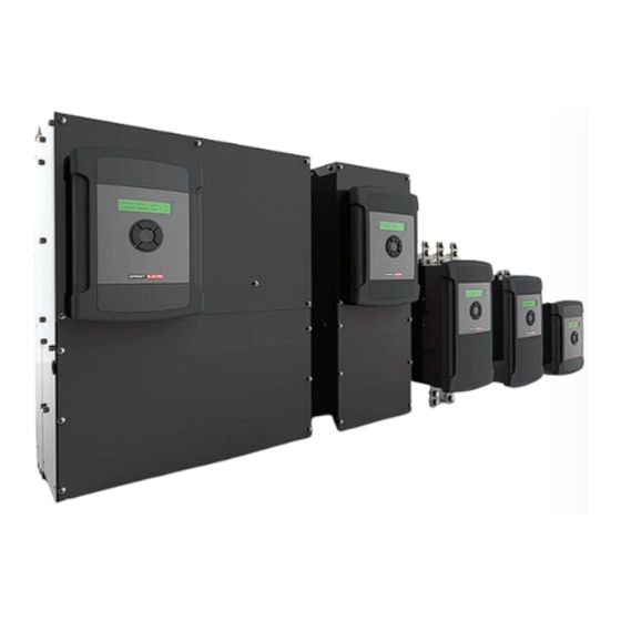
- Page 1 World Class Design | World Class Function | 30 Years Expertise in Industrial Motor Control DC MOTOR DRIVE PL / PLX QuickStart Guide HG107141EN00 Issue 1 (03/2024)
- Page 2 Please read this information before installing or using the product. Install, use and maintain this product following the procedures provided. The manual(s) cannot provide all details, variations and contingencies required for your installation, operation and maintenance of this product or the apparatus with this product installed.
- Page 3 WARNING! Only qualifi ed personnel must install, operate and maintain this equipment. A qualifi ed person is someone technically competent and familiar with all safety information, established safety practices, installation, operation, maintenance and the hazards involved with this equipment and any associated machinery. Hazards This equipment can endanger life through rotating machinery and high voltages.
- Page 4 Weight Consideration should be given to the weight of our heavier products when handling. Risk assessment Under fault conditions or conditions not intended: the motor speed may be incorrect; the motor speed may be excessive; the direction of rotation may be incorrect; the motor may be energised.
-
Page 5: Table Of Contents
Contents: 1 PL/X DC Motor Drive 1 PL/X DC Motor Drive Introduction 1.1.1 Important safety notes .................. 1 Record your CALIBRATION parameter data 1.2.1 Property "S" parameters ................3 Installation 1.3.1 Connect the drive .................... 4 Essential pre-start checks 1.4.1 CHECK LIST: Mechanical ................. -
Page 6: X Dc Motor Drive
1 PL/X DC Motor Drive PL/X DC Motor Drive 1.1 Introduction Follow the steps outlined in this guide to install and initiate the PL/X as a basic speed controller, employing ARMATURE VOLTAGE feedback mode for optimal safety. The PL/X drive displays user-friendly menus and parameter names. Use the key sequences we provide at each step to navigate and edit parameter values with no knowledge of the menu system required. - Page 7 Entering key sequences Use the PL/X keypad to enter the key sequences in the order given. This will navigate the menus in the fewest key presses. LEFT RIGHT Several sequences reset at the Diagnostic Summary screens, located at the top of the menu system. This reset is used as a helpful reference point in case you lose your way.
-
Page 8: Record Your Calibration Parameter Data
1.2 Record your CALIBRATION parameter data Measure the supply voltage and record it below. Also, record the parameter values from the motor and feedback device nameplates for entry into the Calibration menu later. Description Example values Record your value Units Property "S"... -
Page 9: Connect The Drive
1.3 Installation 1.3.1 Connect the drive WARNING! PERSONAL INJURY AND/OR EQUIPMENT DAMAGE HAZARD Before beginning to connect the drive, ensure that all power is OFF. Make sure that you route power and control wiring in separate conduit/cable trays. Wiring must meet all applicable national and local electrical regulations. Make sure that the voltages on the EL1/EL2/EL3 terminals are in-phase with the voltages on L1/L2/L3. - Page 10 PL/X CONTROL WIRING RAMP MAIN I +10VDC CONTRL START CSTOP +24VDC CLAMP SCR ENA CSTOP START Note: Jumper T6 to T27 Figure 2 Control wiring diagram 1.3.1.2 Optional feedback devices ENCODER FEEDBACK +24V EARTH EXTERNAL POWER SUPPLY TWISTED SHIELDED PAIRS TACHO FEEDBACK TACH TACH...
-
Page 11: Essential Pre-Start Checks
1.4 Essential pre-start checks Make the essential mechanical and electrical pre-start checks before applying power to the motor. You need to ensure that you can mark each item on the checklists as completed. Failing to comply with these requirements may cause incorrect functioning or damage to the drive and/or installation - this will invalidate any Warranty. -
Page 12: Check List: Electrical
1.4.2 CHECK LIST: Electrical Tick each each item when complete. Check that all external fuses are of the correct rating and type. The total clearing I t ratings of the main fuse and auxiliary fuse must be smaller in value than the rating specified in the rating tables. -
Page 13: Final Checks Before Applying Power
1.5 Final checks BEFORE applying power • Recheck all wiring, especially the drive's chassis ground. • Use a multimeter to check the L1, L2, L3, F+, F-, A+, and A- terminals for short-circuits to ground. All readings should be greater than 1 MΩ. If any resistances are lower than 1 MΩ, correct them before you apply power. -
Page 14: Quickstart Steps
1.7 QuickStart steps Always commission the drive using ARMATURE VOLTAGE feedback, even if the motor has a dc tacho or encoder. It allows verification of the feedback polarity, ensuring that the motor does not run out of control. WARNING! PERSONAL INJURY AND/OR EQUIPMENT DAMAGE HAZARD Follow the QuickStart steps below as written and in the correct numerical order. - Page 15 Check the control terminals Letter Terminal Function THERMISTOR Complete these checks to ensure that the drive contactor is sequenced correctly before the 3-phase power is applied. START NOTE: The value under the letters TRJSC in the display indicates the actual Control input terminal status. CSTOP Hold down the LEFT key to display the Diagnostic Summary screens.
- Page 16 • Autotune is a static test. • There is no need to disconnect the motor from the load. • The motor field is automatically disabled. • If the motor back emf is detected to be above a certain level implying excessive rotation, Autotune aborts.
- Page 17 Hold down the LEFT key to display the Diagnostic Summary screens. Release the key. Increase the potentiometer setting until the motor turns slowly. Check motor rotation. If L-L-D-R-5xD-R 26)RAMP INPUT it is turning backwards, 75.14 % stop, turn off ALL power to the drive and swap the armature leads (A+ and A-).
-
Page 18: Options
1.8 Options 1.8.1 Feedback 1.8.1.1 Feedback calibration Enter your values from page 3 for DC Tachogenerator or Encoder: Start the drive. Energise the START input (T33) to start the drive. Check the field voltage at the F+ and F- terminals. When the motor is cold, you will measure less than the rated field voltage. -
Page 19: Field Weakening
1.8.1.2 Preparing for Tacho/Encoder use Hold down the LEFT key to display the Diagnostic Summary screens. Release the key. Check to ensure the speed reference is positive (+): R-D-R-R-R 123)TOTAL SPD REF MN 26.50 % Check the sign of the feedback: DC tachogenerator: 129)TACHO VOLTS MON 23.19 AMPS... - Page 20 We may, at our discretion, raise a charge for any faults without notifi cation. repaired that fall outside the warranty cover. www.sprint-electric.com Sprint Electric Limited, Peregrine House, Ford Lane, Ford, Arundel BN18 0DF, U.K. Tel: +44 (0)1243 558080 Fax:+44 (0)1243 558099 Email: info@sprint-electric.com...
Need help?
Do you have a question about the PL Series and is the answer not in the manual?
Questions and answers