Page 1
World Class Design | World Class Function | 30 Years Expertise in Industrial Motor Control
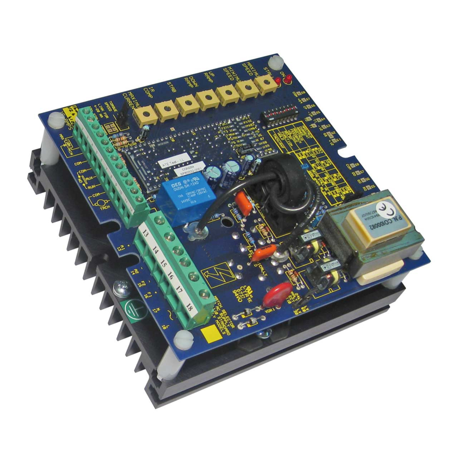
 DC MOTOR DRIVE 1600i / 3200i Product Manual HG105272EN00 Issue 1 (04/2021)
Page 2
Please read this information before installing or using the product. Install, use and maintain this product following the procedures provided. The manual(s) cannot provide all details, variations and contingencies required for your installation, operation and maintenance of this product or the apparatus with this product installed.
Page 3
WARNING! Only qualifi ed personnel must install, operate and maintain this equipment. A qualifi ed person is someone technically competent and familiar with all safety information, established safety practices, installation, operation, maintenance and the hazards involved with this equipment and any associated machinery. Hazards This equipment can endanger life through rotating machinery and high voltages.
Page 4
Weight Consideration should be given to the weight of our heavier products when handling. Risk assessment Under fault conditions or conditions not intended: the motor speed may be incorrect; the motor speed may be excessive; the direction of rotation may be incorrect; the motor may be energised.
Contents 1 Introduction 1 Introduction 2 Installation 2 Installation Motor installation ......................2 Drive Installation ......................2 Guide for systems used in the EU ................4 Multiple drives ....................... 4 Requirements for EMC compliance ................5 Typical applications ....................... 6 2.7 Block diagram and terminal specifications ..............
* USA The 1600i and 3200i have identical functionality, however the 1600i is designed for operation Line-to-Neutral (240 V nominal) and the 3200i for operation Line-to-Line (415 V nominal). • All models are of open chassis construction for use in a suitable enclosure.
This may result in an CONTROL SIGNALS: The 1600i and 3200i uncontrolled current pulse for have isolated control terminals and as such one half mains cycle under may be connected to other systems. Avoid certain conditions, e.g.
Page 9
Mechanical dimensions The unit must have a substantial earth. Connect the earth to the heatsink earth screw provided using a star washer to obtain optimum earth continuity. Fixing bolts: 1600i M5 x 35 mm 3200i M5 x 50 mm ER-1600i 1600i...
2.3 Guide for systems used in the EU Special consideration must be given to installations in member states of the European Union regarding noise suppression and immunity. According to IEC 1800-3 (EN61800-3) the drive units are classified as complex components only for professional assemblers, with no CE marking for EMC. The drive manufacturer is responsible for the provision of installation guidelines. The resulting EMC behaviour is the responsibility of the manufacturer of the system or installation.
2.5 Requirements for EMC compliance • Keep parallel runs of power and control cables at least 0.3 metres apart. Cross-overs must be at right angles. • Keep sensitive components at least 0.3 metres from the drive and power supply cables. •...
DANGER TORQUE MODE SELECTED BY JUMPER ELECTRIC SHOCK RISK RUN CONTACT Figure 6 1600i: Torque control with overspeed limiting by separate setpoint SPRINT ELECTRIC LTD. does not Health and Safety at Work accept any liability whatsoever for Devices constitute a safety hazard. It is...
Page 13
TORQUE MODE SELECTED BY JUMPER ELECTRIC SHOCK RISK RUN CONTACT Figure 9 3200i: Torque control with overspeed limiting by separate setpoint SPRINT ELECTRIC LTD. does not Health and Safety at Work accept any liability whatsoever for Devices constitute a safety hazard. It is...
2.7 Block diagram and terminal specifications 1600i 2.5V RAMP OUTPUT RO 55 4-20mA IR COMP DEMAND DOWN DO 57 +I/P 100K STAB RAMP -I/P 390R 470K LINK RAMP RESET MAX SPEED SPEED 100% HOLD TORQUE RANGE 100K DRIVE S3 S4 7.5V...
Page 15
-24 V T52 or T53 Stall relay driver output, maximum 100 mA, external relay switches to -24 V coil 2K8 from T51 -24 V relay supply, 25 mA - do not short Figure 11 1600i Terminal specifications Installation...
Page 16
+10 V precision reference. 10 mA maximum. Short-circuit proof Minimum end of setpoint potentiometer or 4-20 mA current loop I/P Speed demand input, 0-+10 V for 0-100% speed Common - 4-20 mA return Common - connect to earth for protective Class 1 Auxiliary input - on-board jumper selects direct speed or torque mode (0-10 V for 0-100% control) Connect to COMMON to run 60 ms ON / 20 ms OFF...
IMPORTANT*: The switch settings vary between the 1600i and 3200i. Refer to the table below. For example, if your motor current rating is 6 A, the switch settings for 1600i are SW1:ON and SW2:OFF, but for 3200i/8 they are SW1:OFF and SW2:ON. 1600i : current ranges* 3200i : current ranges* Min.
For an intial start, adjust the following presets: MIN SPEED Fully anti-clockwise UP RAMP Fully anti-clockwise DOWN Fully anti-clockwise RAMP STABILITY Mid-way IR COMP Fully anti-clockwise Set MAX CURRENT from your motor rating plate. Rotating clockwise gives CURRENT 0-100% of the drive current rating as set by switches S1/S2, e.g. if S1/S2 are set to limit the current to 8 A, 50% rotation will give a 4 A current limit.
Page 19
Rotate clockwise to increase current. S1 and S2 select the range. The 3200i is 50 mm wider than the 1600i. 3200i is 50 mm wider than 1600i. A pair of 2 A fuses protect the field and transformer. The supply select jumper is 415/240 located at the top right edge (HIGH/LOW).
4 Options Options Consider the following changes to tune/improve the performance of the drive/system. • SPEED FEEDBACK SELECTION If the system is to use Tacho feedback you can now adjust for the tachogenerator's output voltage, and hence the speed of the motor. Run the drive in Armature Voltage feedback mode and check the polarity of the tacho using a voltmeter.
5 Trouble shooting Trouble shooting The drive consists of two highly accurate feedback control loops. SPEED ERROR Setpoint ramp CURRENT FIRING AND 0 to +10 V AMPLIFIER output on 55. ERROR AMP. BRIDGE 0 - 10 V. output current output phase CIRCUITS demand speed demand...
-24 V UNREGULATED 10 mA +/- 20% +12 V, +10 V, -12 V REGULATED 10 mA 0.01%/DEG C 5% FIELD OUTPUT 0.9 (0.45) x AC SUPPLY. 1600i 1 A, 3200i 2 A. FULL (0.9) OR HALF WAVE (0.45) IP RATING IP00 ALTITUDE...
Page 23
Disposal This product contains materials that are consignable waste under the Hazardous Waste Regulations 2005. Metal and plastic materials can be recycled, however, disposal of the printed circuit board requires compliance with all valid environmental control laws. Products that must be recycled in accordance with the WEEE Regulations are marked with the symbol opposite.
Page 24
We may, at our discretion, raise a charge for any faults without notifi cation. repaired that fall outside the warranty cover. www.sprint-electric.com Sprint Electric Limited, Peregrine House, Ford Lane, Ford, Arundel BN18 0DF, U.K. Tel: +44 (0)1243 558080 Fax:+44 (0)1243 558099 Email: info@sprint-electric.com...
Need help?
Do you have a question about the 1600i and is the answer not in the manual?
Questions and answers