
Related Manuals for Sprint Electric 340XRi


Summary of Contents for Sprint Electric 340XRi
- Page 1 World Class Design | World Class Function | 30 Years Expertise in Industrial Motor Control DC MOTOR DRIVE 340XRi / 680XRi / 1220XRi Product Manual HG105268EN00 Issue 1 (02/2021)
- Page 2 Please read this information before installing or using the product. Install, use and maintain this product following the procedures provided. The manual(s) cannot provide all details, variations and contingencies required for your installation, operation and maintenance of this product or the apparatus with this product installed.
- Page 3 WARNING! Only qualifi ed personnel must install, operate and maintain this equipment. A qualifi ed person is someone technically competent and familiar with all safety information, established safety practices, installation, operation, maintenance and the hazards involved with this equipment and any associated machinery. Hazards This equipment can endanger life through rotating machinery and high voltages.
- Page 4 Weight Consideration should be given to the weight of our heavier products when handling. Risk assessment Under fault conditions or conditions not intended: the motor speed may be incorrect; the motor speed may be excessive; the direction of rotation may be incorrect; the motor may be energised.
-
Page 5: Table Of Contents
Contents: 1 Introduction 1 Introduction 2 Installation 2 Installation Motor installation Drive installation 2.2.1 Initial settings - without power 2.2.2 Mechanical installation 2.2.3 Electrical installation 2.2.4 Block diagram 3 Operation 3 Operation Pre-operation motor check list Operating the drive 4 Options 4 Options 5 Specifications 5 Specifications... -
Page 6: Introduction
1 Introduction Introduction The 340XRi / 680XRi / 1220XRi DC Drive is an isolated, 4 Quadrant speed controller for brushed shunt wound or permanent magnet DC motors. This Class 1 product has basic insulation and a protective earth. Its control signals are isolated from the mains AC supply, and their connection to other isolated instruments is permitted. -
Page 7: Installation
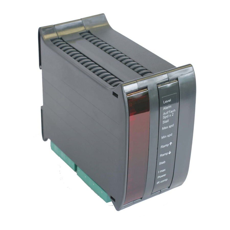
2 Installation Installation 2.1 Motor installation • Foot-mounted motors must be level and secure. • Ensure accurate alignment of the motor shaft and couplings. • Do not hammer pulleys or couplings onto the motor shaft. • Protect the motor from ingress of foreign matter during installation. NOTE: This drive does not provide motor over-temperature protection. - Page 8 WARNING! When power is applied to the drive, ALWAYS use an insulated tool when adjusting the presets. USER ADJUSTMENTS Level: relay driver threshold. +/-(0.5% to 105%). (+/-10.5V). Symmetrical about zero. Level “Fan failure” alarm is active when lit. Alarm Refer to "3.2 Operating the drive" on page 13. Refer to text.
-
Page 9: Initial Settings - Without Power
3.4 A (340XRi drive), 6.8 A (680XRi drive), 12.2 A (1220XRi drive) For example, to adjust the preset on an 340XRi drive for a motor with an armature current rating of 1.7 A, set it to 50%. Use a suitable current meter temporarily connected in series with the armature to achieve accurate settings. -
Page 10: Electrical Installation
Built-in functions are ± channel with push button control inputs, and relay driver with variable threshold * Potentiometer, graduated dial and knob - Sprint Electric part number: POTKIT EMC wiring: If the unit is going to be used in the domestic environment, then for installations in the EU, a supply filter is recommended in order to comply with EN61800-3. - Page 11 WARNING! PERSONAL INJURY HAZARD Terminals A+, A-, F-, F+, N & L are at high potential. Do not touch the terminals or any connected conductor. DANGER! 2-pole ELECTRIC AC supply SHOCK switch or HAZARD contactor semi- MOTOR MOTOR conductor Assumes u ARMATURE FIELD fuse...
- Page 12 Centre off change-over switch Wiring for Ramped Forward / Stop / Reverse switch DANGER! ELECTRIC START or SHOCK Optional TACH RUN switch RAMP TO Clean HAZARD Close to common STOP Earth Open for coast to stop speed feedback switch Basic single direction speed control with tach feedback Protective Earth: The drive's 0 V (COM) connection at Terminal 10 (or Terminal 5) MUST be connected to a clean Protective Earth.
- Page 13 CONTROL TERMINAL LISTING - tightening torque: 0.25 Nm (2.2 lbf.in) Optional OP± ±10.5 V range. 10 mA maximum. This terminal outputs the input supplied to speed indicator Terminal 6, as affected by the states of Terminals 7 and 8 (pushbuttons). +5 V = 100% Optional From the Truth Table below:...
- Page 14 CONTROL TERMINAL LISTING - tightening torque: 0.25 Nm (2.2 lbf.in) RUN Internal 12K pull-up to +12 V. Close Terminal 9 to COMMON to run the drive. Open Terminal 9 to stop - this will cause immediate drive inhibit; if the motor is rotating at the time it will coast to STOP (zero speed).
- Page 15 CONTROL TERMINAL LISTING - tightening torque: 0.25 Nm (2.2 lbf.in) RLIP Relay driver input. Accepts 0 to ±10.5 V signal inputs. The threshold to activate the relay driver is symmetrical around zero. This is set by the LEVEL preset, between ±0.05 V and ±10.5 V. When the T13 input exceeds the positive or negative threshold, then the T12 RELAY DRIVER OUTPUT is turned ON.
- Page 16 CONTROL TERMINAL LISTING - tightening torque: 0.25 Nm (2.2 lbf.in) TRIP This output goes high (+10.5 V at 10 mA) and latches high when the stall timer has timed out (in which case T14 OVLD will also be high), OR if the fan alarm has operated (in which case T14 OVLD will be low).
-
Page 17: Block Diagram
2.2.4 Block diagram Installation... -
Page 18: Operation
3 Operation Operation 3.1 Pre-operation motor check list With no power applied, complete the following check list: • Check for the correct insulation between individual motor elements, and between these elements and the earthed motor frame. Disconnect all drive cables before testing. - Page 19 Avf/Tach Avf/Tach Increasing br rating (ranges given below): Spd x 2 Spd x 2 340XRi / 680XRi / 1220XRi 340XRi LV60 / 680XRi LV60 / 1220XRi LV60 Stall Maximum s (armature or 40 to 100 V 10 to 25 V...
-
Page 20: Options
4 Options Options • Speed Feedback selection: If the system is to use Tacho feedback you can now adjust for the tachogenerator's output voltage, and hence the speed of the motor. Run the drive in Armature Voltage feedback mode and check the polarity of the tacho using a voltmeter. - Page 21 • Alarms WARNING! PERSONAL INJURY HAZARD The following alarm provides an electronic armature current inhibit function. The field output remains energised and all power terminals are LIVE (shock hazard), hence these terminals must not be relied upon to ensure the machine is stationary during hazardous operations.
- Page 22 • Alternative wiring option The wiring diagram below shows the addition of speed and current indicators on Terminal 18 and Terminal 19 respectively. The +10V reference (T1) is inverted by connecting it to T6 to produce a -10V ref on T4. The changeover centre-zero switch then selects forward (+10V), reverse (-10V), or centre off for a ramp to zero.
-
Page 23: Specifications
(Vdc) (Adc) (Adc max) (kW / hp) 340XRi 110 or 240 90–180 (200 V max) 0.55 / 0.5 340XRi LV60 30 or 60 24–48 (50 V max) 680XRi 110 or 240 90–180 (200 V max) 0.75 / 1 680XRi LV60 30 or 60 24–48 (50 V max) - Page 24 We may, at our discretion, raise a charge for any faults without notifi cation. repaired that fall outside the warranty cover. www.sprint-electric.com Sprint Electric Limited, Peregrine House, Ford Lane, Ford, Arundel BN18 0DF, U.K. Tel: +44 (0)1243 558080 Fax:+44 (0)1243 558099 Email: info@sprint-electric.com HG105268EN00 Issue 1...
Need help?
Do you have a question about the 340XRi and is the answer not in the manual?
Questions and answers