
Related Manuals for Sprint Electric 4Q 3600XRi


Summary of Contents for Sprint Electric 4Q 3600XRi
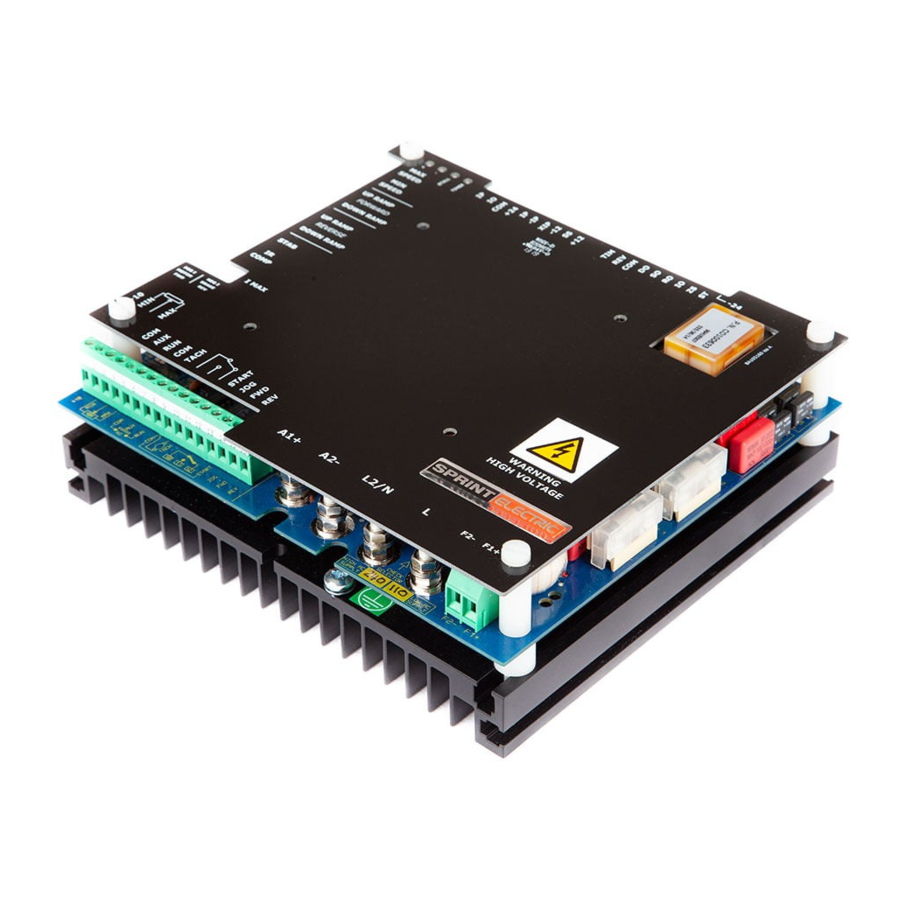
- Page 1 World Class Design | World Class Function | 30 Years Expertise in Industrial Motor Control DC MOTOR DRIVE 3600XRi Product Manual HG105273EN00 Issue 1 (03/2021)
- Page 2 Please read this information before installing or using the product. Install, use and maintain this product following the procedures provided. The manual(s) cannot provide all details, variations and contingencies required for your installation, operation and maintenance of this product or the apparatus with this product installed.
- Page 3 WARNING! Only qualifi ed personnel must install, operate and maintain this equipment. A qualifi ed person is someone technically competent and familiar with all safety information, established safety practices, installation, operation, maintenance and the hazards involved with this equipment and any associated machinery. Hazards This equipment can endanger life through rotating machinery and high voltages.
- Page 4 Weight Consideration should be given to the weight of our heavier products when handling. Risk assessment Under fault conditions or conditions not intended: the motor speed may be incorrect; the motor speed may be excessive; the direction of rotation may be incorrect; the motor may be energised.
-
Page 5: Table Of Contents
Contents 1 Introduction 1 Introduction 2 Mechanical dimensions 2 Mechanical dimensions 3 Guide for systems used in the EU 3 Guide for systems used in the EU 4 Multiple drives 4 Multiple drives 5 Requirements for EMC compliance 5 Requirements for EMC compliance 6 Installation 6 Installation Motor installation ...................... -
Page 7: Introduction
1 Introduction Introduction The 3600XRi DC Drive is an isolated, 4 Quadrant speed controller for brushed shunt wound or permanent magnet DC motors. This Class 1 product has basic insulation and protective earth. Its control signals are isolated from the mains AC supply, and their connection to other isolated instruments is permitted. -
Page 8: Mechanical Dimensions
2 Mechanical dimensions Mechanical dimensions Mount the unit using the two centre fixing slots, and allow satisfactory cooling air to flow over the fins (vertically, with 50 mm end space). The unit must have a substantial earth connection. Connect the earth (cross-sectional area at least 6 mm ) to the heatsink earth screw provided. -
Page 9: Guide For Systems Used In The Eu
3 Guide for systems used in the EU Guide for systems used in the EU Special consideration must be given to installations in member states of the European Union regarding noise suppression and immunity. According to IEC 1800-3 (EN61800-3), the drive units are classified as complex components only for professional assemblers, with no CE marking for EMC. -
Page 10: Requirements For Emc Compliance
5 Requirements for EMC compliance Requirements for EMC compliance • Keep parallel runs of power and control cables at least 0.3 metres apart. Cross-overs must be at right angles. • Keep sensitive components at least 0.3 metres from the drive and power supply cables. •... -
Page 11: Installation
6 Installation Installation AC supply. Failure to use the correct WARNING! semiconductor fuse ratings will invalidate any warranty. Special consideration must ELECTRIC SHOCK HAZARD be given to installations in member states Disconnect the mains supply of the EU. Refer to "5 Requirements for EMC before working on the unit. -
Page 12: Typical Applications
6.3 Typical applications SPRINT ELECTRIC LTD. does not Health and Safety at Work accept any liability whatsoever for Devices constitute a safety hazard. It is the installation, fitness for purpose or the responsibility of the user to ensure application of its products. It is the users compliance with any Acts or By-Laws in force. -
Page 13: Commissioning
7 Commissioning Commissioning 7.1 Initial settings - without power The suggested Comissioning strategy is to start in the safest possible mode of operation and progressively exercise each element of the system until full functionality has been achieved. For this reason, all drive units are shipped to run using the: •... -
Page 14: Block Diagram
7.2 Block diagram * NOTE: Fit only one link to SPEED, 2Q and 4Q (marked below with *) at any time. Refer to "7.4.3.3 Torque/Speed Mode" on page 16. Commissioning... - Page 15 Commissioning...
- Page 16 WARNING! When power is applied to the drive, ALWAYS use an insulated tool when adjusting the presets. Stall lamp lights and drive quenches if the stall timer When ON, positive current demand. trips - the time depends on the current demand: STANDARD WITH 50% THRESHOLD When ON, negative current demand.
-
Page 17: Terminal Descriptions
7.3 Terminal descriptions 7.3.1 Control terminals 1 +10 +10 V precision reference. 10 mA maximum. Short-circuit proof. 2 MIN Minimum (ACW) end of setpoint potentiometer, or 4-20 / 0-20 mA current loop input. 3 I/P +/-10 V input for speed setpoint. Maximum (CW) end of setpoint pot in bi-directional systems. - Page 18 7.3.2 Ancillary terminals 51 -24 -24 V relay supply. 25 mA. NOT SHORT-CIRCUIT PROOF Stall relay driver output. Maximum 25 mA. External relay is de-energised when stall timer trips if 52 ST connected as in "Figure 7 Relay circuits" on page 13. Zero speed relay driver output.
- Page 19 7.3.3 Power terminals Terminals 52, 53, 59, 60 Minimum coil resistance 2k8 Ω Terminal 51 (-24 V) Figure 7 Relay circuits Motor armature connection (positive). Motor armature connection (negative). L2/N Line ac return; either neutral or L2. Line ac supply input. Motor field connection (negative).
-
Page 20: Preset, Switches And Links
7.4 Preset, switches and links 7.4.1 Presets Preset Description MAX SPEED Sets maximum speed for 100% demand. Sets minimum speed for application. Note: Minimum speed function only operates if the speed demand is from a 10k potentiometer connected MIN SPEED between terminals 1 and 2 with its wiper connected to terminal 3. - Page 21 7.4.2.2 S3 / S4 These two switches set the range of the speed feedback voltage. Adjustment within the range is through the MAX Speed preset. Speed Feedback Voltage 25 - 50 V 50 - 100 V 100 - 200 V 200 - 400 V 7.4.2.3 S5 / S6 / S7...
- Page 22 7.4.3.2 Maximum Current Mode There are three link positions which determine the function of the MAX CURRENT presets (P6 and P10). POS I/NEG I: When the link is in this position, P6 sets the positive current limit and P10 sets the negative current limit irrespective of the direction of rotation of the motor.
- Page 23 7.4.3.5 Quench Mode There are three link positions that determine the behaviour of the quench circuit. The factory setting is for the FS and ZS links to be fitted. Note that opening the RUN input always resets the setpoint ramp output to zero. The other effects of opening the RUN input depend on the position of the links below.
-
Page 24: Pre-Operation Motor Check List
7.5 Pre-operation motor check list With no power applied, complete the following check list: • Check for the correct insulation between all motor windings and earth (disconnect all drive cables before testing). • Check inside the motor connection box for foreign objects, damaged terminals etc. •... -
Page 25: Bi-Directional Operation
Run the motor at maximum speed setpoint and adjust the MAX SPEED preset to achieve the armature voltage stated on the motor rating plate. Refer to the Warning above. Rotate the potentiometer fully counter-clockwise and ramp the drive to zero. If required, adjust the MIN SPEED preset. -
Page 26: Options
8 Options Options Consider the following changes to tune/improve the performance of the drive/system. 8.1 Torque Control Mode The drive can control the torque (current) of the motor, instead of the speed (volts), by allowing an external input to clamp the current demand. NOTE: The speed loop then provides the current demand, and hence the speed loop must always be asking for more current than the clamp level. -
Page 27: Maximum Current Mode
8.2 Maximum Current Mode Refer to "7.4.3.2 Maximum Current Mode" on page 16 for details of the link settings. The MAX CURRENT pots control the mode selected by the current MODE jumper. Refer to the quadrant diagram above to see the physical effect. P6 POS I, quadrants 1 and 2 P10 NEG I, quadrants 3 and 4. - Page 28 The effect on the motor speed for each of the link positions can be seen in the graphs below. It is also possible to use links in more than one position. The factory setting is for the FS and TABLE OF OPERATING MODES BASIC CONNECTION.
-
Page 29: Stall Mode
8.4 Stall Mode NOTE: Selecting 2Q or 4Q torque mode inhibits stall, provided the torque limit applied to T6 does not exceed 105%. The drive regulates the motor speed by adjusting the demand to the current control loop to control motor armature current and hence torque. If the torque required by the load exceeds that which the motor can produce, the motor will stall. -
Page 30: Optional Start (Ramp To Stop)
8.5 Optional START (ramp to stop) OPTIONAL START (ramp to zero) setpoint ramp speed setpoint +24 V STOP START START RELAY • Energising RL2 using the optional START push button connects the speed setpoint to the setpoint ramp. • De-energising RL2 by opening the STOP push button removes the speed setpoint on I/P (T3) causing the ramp output to reduce the value on XIP (T64) and the auxiliary input. -
Page 31: Trouble Shooting
9 Trouble shooting Trouble shooting PROBLEM LIKELY CAUSES REMEDY Drive will not Line fuses blown POWER OFF! Check circuits and replace power-up, or no ON fuses with correct type (see Rating table, indication page 28) On-board F1, F2 fuses blown Check field wiring Damaged transformer Check supply select jumper... -
Page 32: Specifications
10 Specifications Specifications 10.1 Technical specifications Function control action dual loop proportional + integral feedback method tachometer/armature voltage switch select 0-100% regulation 0.1% typical (tacho); 2% typical (armature voltage) max. torque speed range 100:1 (tacho); 20:1 (armature voltage) overload 150% continuous current for 30s Inputs Analogue Pushbutton functions... - Page 33 Vibration 0.075 mm displacement 10 – 58 Hz 1g acceleration 58 – 150 Hz IP Rating IP00 Protection Rating Fuse Fuseholder Clearing I CH00608A CP102071 35 A Supply fusing CH00620A CP102071 259 A 16 A CH00730A CP102053 265 A 32 A CH00850A CP102054 770 A...
-
Page 34: Rating Table
10.2 Rating table APPLICATION AREA: Industrial (non-consumer) "Motor speed control utilising DC Motors". Each drive has the same features and terminals. Select the appropriate model depending on the motor current and the available supply voltage. AC SUPPLY NOMINAL 100% Amps DRIVE TYPE MAXIMUM I DUAL... - Page 36 We may, at our discretion, raise a charge for any faults without notifi cation. repaired that fall outside the warranty cover. www.sprint-electric.com Sprint Electric Limited, Peregrine House, Ford Lane, Ford, Arundel BN18 0DF, U.K. Tel: +44 (0)1243 558080 Fax:+44 (0)1243 558099 Email: info@sprint-electric.com...
Need help?
Do you have a question about the 4Q 3600XRi and is the answer not in the manual?
Questions and answers