
Related Manuals for Sprint Electric 200XLV


Summary of Contents for Sprint Electric 200XLV
- Page 1 World Class Design | World Class Function | 30 Years Expertise in Industrial Motor Control DC MOTOR DRIVE 200XLV Product Manual HG105277EN00 Issue 1 (06/2022)
- Page 2 Please read this information before installing or using the product. Install, use and maintain this product following the procedures provided. The manual(s) cannot provide all details, variations and contingencies required for your installation, operation and maintenance of this product or the apparatus with this product installed.
- Page 3 WARNING! Only qualifi ed personnel must install, operate and maintain this equipment. A qualifi ed person is someone technically competent and familiar with all safety information, established safety practices, installation, operation, maintenance and the hazards involved with this equipment and any associated machinery. Hazards This equipment can endanger life through rotating machinery and high voltages.
- Page 4 Weight Consideration should be given to the weight of our heavier products when handling. Risk assessment Under fault conditions or conditions not intended: the motor speed may be incorrect; the motor speed may be excessive; the direction of rotation may be incorrect; the motor may be energised.
-
Page 5: Table Of Contents
Contents: 1 Introduction 1 Introduction Description 1.1.1 External DC Power Supply Considerations ........... 2 1.1.2 Output current and supply voltage ............... 3 1.1.3 Power output and heatsink ................4 1.1.4 Overload trip ....................5 2 Installation 2 Installation Motor installation Drive Installation 3 Mechanical dimensions 3 Mechanical dimensions... -
Page 7: Introduction
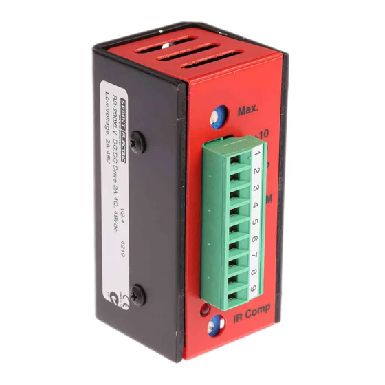
The 200XLV is quick and easy to install. It is very compact and can mount on a back panel or DIN rail, and all connections are accessible from the front of the product. This product conforms to IP00 protection. -
Page 8: External Dc Power Supply Considerations
If this occurs, extra cooling is required by fixing the 200XLV to a metal surface, a heatsink, or by fan cooling. Refer to "1.1.3 Power output and heatsink" on page 4. -
Page 9: Output Current And Supply Voltage
1.1.2 Output current and supply voltage The 200XLV provides a maximum of ±2 A of continuous current, depending on the armature (AV) and supply voltage (V It requires a supply of at least (8 V + AVmax) to deliver the maximum output current. -
Page 10: Power Output And Heatsink
The unit casing acts as a heatsink and may become too hot to touch. The 200XLV has an automatic thermal limiting device that prevents excess dissipation from damaging the unit. When motoring, the output capability depends on the dissipation (WD) in the drive, where WD = Amps x (V –... -
Page 11: Overload Trip
1.1.4 Overload trip The 200XLV has an overload-inverse time-trip device (Figures 4 and 5). 100% Figure 4 Maximum continuous current vs ambient temperature 1000 s 40°C Ambient temperature 150% 140% 130% Figure 5 Trip 120% time vs maximum current limit... -
Page 12: Installation
• If the armature voltage rating exceeds the 200XLV drive voltage, the motor's rated speed becomes unachievable. You can also use the 200XLV drive to control the current in other inductive loads (e.g. linear actuators). Typically, this requires the drive to be operating in the Unipolar Current Control mode (refer to "4 Typical applications"... -
Page 13: Mechanical Dimensions
3 Mechanical dimensions Mechanical dimensions Dimensions are in millimetres CAUTION! EQUIPMENT DAMAGE HAZARD This product conforms to IP00 protection. Consider the installations environmental conditions for safe and reliable operation. To access the three M4 fixing holes, remove the plug from the terminals and lift away the plastic cover. -
Page 14: Typical Applications
4 Typical applications Typical applications 4.1 Speed control NOTE: The A and B diagrams below have the same functionality, except that diagram B has an external potentiometer for adjusting the output voltage to a precise zero. The zero drift over the entire temperature range is less than ±100 mV and is usually less than the motor starting voltage. - Page 15 0 TO ±V SIGNAL 0 TO ±V SIGNAL FROM EXTERNAL FROM EXTERNAL SOURCE SOURCE 3 A FUSE 3 A FUSE COMMON OF EXTERNAL SOURCE COMMON OF EXTERNAL SOURCE Figure 10 0 to ±5 V or ±10 V speed signal In Figure 10 B, the external source common is not at the same potential as the supply 0 V. 0 TO +V SIGNAL FROM EXTERNAL 0 TO +V SIGNAL...
-
Page 16: Torque Control
4.2 Torque control Top jumper Sense 0 TO ±5 V SIGNAL resistor FROM EXTERNAL SOURCE 3 A FUSE COMMON OF EXTERNAL SOURCE Bottom jumper Figure 13 Torque circuit control Insert a sense resistor in the A+ output, terminal Input Sense Output 8. -
Page 17: Terminal Descriptions
V- Negative dc power supply input V+ Positive dc power supply input A+ Armature connection A- Armature connection 6 Block diagram Block diagram 5 mA, 10 V IR COMP F1 V+ 5 mA, 5 V READY Figure 17 200XLV block diagram Terminal descriptions... -
Page 18: Commissioning
7 Commissioning Commissioning The suggested Commissioning strategy starts in the safest possible mode of operation and progressively exercises each element of the system to achieve full functionality. For this reason, we ship all drive units to run using: • The highest supply option •... -
Page 19: Operating The Drive
7.3 Operating the drive 12. Apply power to the drive. Slowly increase the external demand. Is the motor turning in the required direction? If not, reverse the system by transposing the A+ and A- motor armature connections. CAUTION! When reversing the system: To prevent damage, do not transpose the motor armature connections until the motor has stopped rotating. -
Page 20: Options
8 Options Options The 200XLV provides the following extra functions (that may require you to supply additional parts). Access these by removing the terminals and cover from the unit. 8.1 PID feedback Change the input amplifier feedback network to P (Proportional), PI (proportional + integral) or PID (proportional + integral + derivative) mode by using the 3-position top jumper. -
Page 21: Setpoint Ramp (Ramp Caps)
8.2 Setpoint ramp (RAMP CAPS) The 200XLV is capable of rapid response to step demand changes. However, you can use this facility to limit the motor slew rate if rapid speed changes or high peak current are undesirable. -
Page 22: Max Preset Adjustment
9 MAX preset adjustment MAX preset adjustment 9.1 ARMATURE VOLTAGE control mode (speed control) Refer to "Figure 18 Jumper and link positions" on page 14. When using AV mode, the MAX preset operates as a speed control: • With the top and bottom proportional gain links fitted, the MAX preset range adjustment is ±4 V to ±25 V for a 5 V speed demand. -
Page 23: Trouble Shooting
To restart the drive after a trip occurs, correct the cause for the trip and then restart. A trip can occur during commissioning and normal operation, causing the drive to stop. If the trip condition persists, it will not be possible to restart the drive. Return the 200XLV to Sprint Electric Ltd. -
Page 24: Specifications
11 Specifications Specifications All specifications in this document are nominal. This product conforms to IP00 protection. Specification Voltage limit For dc motors with a maximum armature voltage ratings from ±6 V to ±48 Vdc Current limit 0 to ±2 A continuous; ±3 A peak Input supply 12 to 48 Vdc ±25%;... - Page 25 We may, at our discretion, raise a charge for any faults without notifi cation. repaired that fall outside the warranty cover. www.sprint-electric.com Sprint Electric Limited, Peregrine House, Ford Lane, Ford, Arundel BN18 0DF, U.K. Tel: +44 (0)1243 558080 Fax:+44 (0)1243 558099 Email: info@sprint-electric.com...
Need help?
Do you have a question about the 200XLV and is the answer not in the manual?
Questions and answers