Table of Contents
Advertisement
Available languages
Available languages
Quick Links
Federal regulations require ceiling fans
with light kits manufactured or imported
after January 1, 2009, to limit total
wattage consumed by the light kit to
190W.
Therefore, this fan is equipped
with a wattage limiting device.
Installation Guide
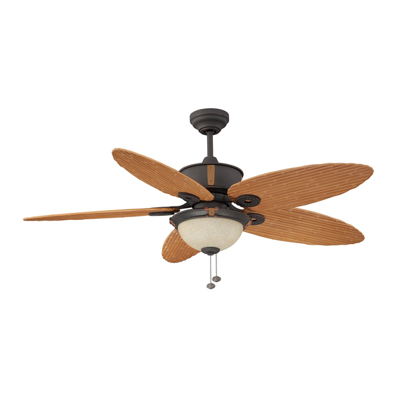
For Model:
E-EH52NON5C1S
LISTED
For
Damp Location
E192641
net weight of fan: 21.38 lb. (9.7 kg)
READ THESE INSTRUCTIONS
AND SAVE THEM FOR FUTURE USE
Table of Contents:
Safety Tips. pg. 1
Unpacking Your Fan. pg. 2
Parts Inventory. pg. 2
Installation Preparation. pg. 3
Hanging Bracket Installation. pg. 3
Fan Assembly. pgs. 4 - 5
Wiring. pg. 5
Canopy Assembly. pg. 6
Blade Assembly. pg. 6
Switch Housing Assembly. pg. 7
Testing Your Fan. pg. 9
Troubleshooting. pg 10
Warranty. pg. 10
Parts Replacement. pg. 10
PRINTED IN CHINA
Advertisement
Chapters
Table of Contents

Related Manuals for Litex Industries E-EH52NON5C1S


Summary of Contents for Litex Industries E-EH52NON5C1S
-
Page 1: Table Of Contents
190W. Therefore, this fan is equipped with a wattage limiting device. Installation Guide For Model: E-EH52NON5C1S Table of Contents: Safety Tips. pg. 1 Unpacking Your Fan. pg. 2 Parts Inventory. pg. 2 Installation Preparation. pg. 3 Hanging Bracket Installation. -
Page 2: Safety Tips
SAFETY TIPS. WARNING: To reduce the risk of electrical shock, turn off the electricity to the fan at the main fuse box or circuit panel before you begin the fan installation or before servicing the fan or installing accessories. CAUTION: To avoid personal injury, the use of gloves may be necessary while handling fan parts with sharp edges. -
Page 3: Unpacking Your Fan
1. Unpacking Your Fan. Carefully open the packaging. Remove items from Styrofoam inserts. Remove motor housing and place on carpet or Styrofoam to avoid damage to finish. Do not discard fan carton or Styrofoam inserts should this fan need to be returned for repairs. -
Page 4: Installation Preparation
3. Installation Preparation. blade edge To prevent personal injury and damage, ensure inches that the hanging location allows the blades a (76cm) 7 feet (2.13m) clearance of 7ft. (2.13m) from the floor and 30in. (76cm) from any wall or obstruction. 12ft. -
Page 5: Fan Assembly. Pgs
5. Fan Assembly. set screw hole If you wish to extend the hanging length of set screw your fan, you must remove the hanging ball stop pin from the 6in. downrod provided to use with an extended downrod (sold separately). [If you wish to use the 6in. -
Page 6: Wiring
5. Fan Assembly. (cont.) With the hanging bracket secured to the outlet box and able to support the fan, you are now hanging bracket tab ready to hang your fan. Grab the fan firmly with hanging ball slot two hands. Slide downrod through opening in hanging bracket and let hanging ball rest on the hanging bracket. -
Page 7: Canopy Assembly
7. Canopy Assembly. hanging bracket Locate 2 screws on underside of hanging bracket and remove screw closest to the open end of the hanging bracket. Partially loosen the other screw. screw Lift canopy to hanging bracket. Place rounded part of slotted hole in canopy over loosened screw in hanging bracket and push up. -
Page 8: Switch Housing Assembly
9. Switch Housing Assembly. Remove 1 screw from fitter plate on underside of motor and partially loosen the motor other 2 screws. Align slotted holes in center housing of switch housing with loosened screws in fitter plate, allowing male plug from motor housing to come through hole in middle of switch housing. - Page 9 10. Light Kit Assembly (Optional). (cont.) Remove finial, finial plate and threaded washer from light kit fitter. Guide pull chain on switch housing through hole in top of light kit fitter, then raise glass shade in order to guide pull chains through corresponding holes at the bottom of the glass shade.
-
Page 10: Testing Your Fan
11. Testing Your Fan. It is recommended that you test fan before finalizing installation. Restore power from circuit box and light reverse switch switch (if applicable). Test fan speeds with the pull chain on switch housing. Start at the OFF position (no blade movement). -
Page 11: Troubleshooting
Service at 1-800-527-1292 to arrange for return of fan. 1. Check wall switch to fan. Return fan, shipping prepaid to Litex Industries, Ltd. We will 2. Verify that reverse switch is set completely in repair or ship you a replacement fan, and we will pay the either direction. - Page 12 Por lo tanto, este ventilador tiene un aparato que sirve para limitar el vatiaje. Guía de instalación Para modelo: E-EH52NON5C1S Indice de materias: Sugerencias de seguridad. Pág. 1 Desempaquetado del ventilador. Pág. 2 Inventario de piezas. Pág. 2 Preparación para la instalación. Pág. 3 Instalación del soporte de montaje.
-
Page 13: Sugerencias De Seguridad. Pág
SUGERENCIAS DE SEGURIDAD. ADVERTENCIA: Para evitar la posibilidad de una descarga eléctrica, desconectar la corriente en la caja de fusibles principal o el interruptor protector antes de iniciar la instalación del ventilador o antes de repararlo o instalar accesorios. LEER TODAS LAS INSTRUCCIONES E INFORMACIÓN DE SEGURIDAD CUIDADOSAMENTE ANTES DE INSTALAR SU VENTILADOR Y GUARDAR ESTAS INSTRUCCIONES. -
Page 14: Desempaquetado Del Ventilador. Pág
1. Desempaquetado del ventilador. Abrir el empaque cuidadosamente. Sacar los artículos del embalaje. Sacar el motor y ponerlo en una alfombra o en el embalaje para evitar rayar el acabado. Guardar la caja de cartón o el empaquetamiento original en caso de que tenga que mandar el ventilador para alguna reparación. -
Page 15: Preparación Para La Instalación. Pág
3. Preparación para la instalación. borde del aspa Para prevenir daño corporal y otros daños, estar 76cm seguro de que el lugar en donde va a colgar el 2,13m pulg.) ventilador le permite un espacio libre de 2,13m (7 (7 pies) pies) entre las puntas de las aspas y el piso y 76cm (30 pulg.) entre las aspas y cualquier pared u otra obstrucción. -
Page 16: Ensamblaje Del Ventilador. Págs
5. Ensamblaje del ventilador. agujero para el Si usted desea extender la longitud colgante del tornillo de fijación tornillo de fijación ventilador, usted tendrá que quitar la bola que sirve perno para colgar del tubo de 15,24cm provisto para usarla de tope con un tubo más largo (a la venta por separado). -
Page 17: Instalación Eléctrica. Pág
5. Ensamblaje del ventilador. (cont.) Ya que esté sujetado el soporte de montaje a la caja de parte saliente del salida y capaz de apoyar el ventilador, usted está listo para soporte de montaje colgar el ventilador. Agarrar el ventilador firmemente con ranura en la bola las dos manos. -
Page 18: Colocación De La Cubierta Decorativa. Pág
7. Colocación de la cubierta decorativa. Localizar los 2 tornillos en la parte inferior del soporte de montaje y quitar el tornillo que está localizado más cerca del extremo abierto del soporte de montaje. Aflojar parcialmente el otro tornillo. Elevar la cubierta decorativa hasta el soporte de montaje. -
Page 19: Instalación De La Caja De Encendido. Pág
9. Instalación de la caja de encendido. Quitar 1 tornillo de la placa de conexión en la parte inferior del motor y aflojar los otros 2 tornillos. Alinear los agujeros con ranura de bastidor del en medio de la caja de encendido con los motor tornillos aflojados en la placa de conexión, dejando que el enchufe macho del bastidor... - Page 20 10. Instalación del juego de luz (opcional). (cont.) Quitar el adorno con rosca, la placa del adorno con rosca y la arandela con rosca del conectador para el juego de luz. Pasar la cadena de encendido en la caja de encendido por el agujero en la parte de arriba del conectador para el juego de luz.
-
Page 21: Verificación Del Funcionamiento Del
11. Verificación del funcionamiento del ventilador. Se le recomienda poner el ventilador a prueba antes de terminar la instalación. Regresar la corriente de electricidad en el cortacircuitos y encender el interruptor de la luz en la pared (si se aplica). Verificar las velocidades interruptor de del ventilador con la cadena de encendido en la caja de reversa... - Page 22 Asegurarse de que se conectaron bien los enchufes Ni Litex Industries ni el fabricante se harán responsables macho y hembra en el conectador para el juego de luz. por lo que pasa por una instalación inadecuada o el uso 5.
Need help?
Do you have a question about the E-EH52NON5C1S and is the answer not in the manual?
Questions and answers