
Related Manuals for HMS Networks Anybus Communicator SP2954


Summary of Contents for HMS Networks Anybus Communicator SP2954
- Page 1 ENGLISH ® ™ Anybus Communicator - PROFINET to Modbus RTU/Serial STARTUP GUIDE SP2954 Version 1.12 Publication date 2024-05-02...
- Page 2 The information in this document shall therefore not be construed as a commitment on the part of HMS Networks and is subject to change without notice. HMS Networks makes no commitment to update or keep current the information in this document.
-
Page 3: About This Document
® ™ Preface Anybus Communicator - PROFINET to Modbus RTU/Serial 1. Preface 1.1. About This Document ® ™ This document describes how to install Anybus Communicator For additional documentation and software downloads, FAQs, troubleshooting guides and technical support, please visit www.anybus.com/support. 1.2. -
Page 4: Information Symbols
Additional information which may facilitate installation and/or operation. Helpful advice and suggestions. 1.3. Trademarks ® Anybus is a registered trademark of HMS Networks. All other trademarks are the property of their respective holders. Page 2 of 28 SP2954 Version 1.12... -
Page 5: Intended Use
® ™ Safety Anybus Communicator - PROFINET to Modbus RTU/Serial 2. Safety 2.1. Intended Use The intended use of this equipment is as a communication interface and gateway. The equipment receives and transmits data on various physical layers and connection types. - Page 6 ® ™ Anybus Communicator - PROFINET to Modbus Cybersecurity RTU/Serial 3. Cybersecurity 3.1. General Cybersecurity IMPORTANT It is important to maintain the cybersecurity of the Communicator. Before connecting the Communicator to a PLC, ensure the PLC is configured and installed in accordance with the PLC supplier hardening guidelines.
- Page 7 ® ™ Preparation Anybus Communicator - PROFINET to Modbus RTU/Serial 4. Preparation 4.1. Cabling Have the following cables available: • Power cable. • Ethernet cable for configuration. • Ethernet cable x 1 for connecting to the network. • 7-pin screw terminal block connector is included with the product. 4.2.
-
Page 8: Software License Information
® ™ Anybus Communicator - PROFINET to Modbus Software License Information RTU/Serial 4.4. Software License Information For license agreements regarding the third-party software used in the Communicator, refer to the LICENSE.txt file(s) included in the Communicator firmware update package zip file. - Page 9 ® ™ Support and Resources Anybus Communicator - PROFINET to Modbus RTU/Serial 4.5. Support and Resources For additional documentation and software downloads, FAQs, troubleshooting guides and technical support, please scan the QR code to visit the Communicator support web page. You can also visit www.anybus.com/support and enter the product article number to...
-
Page 10: Installation
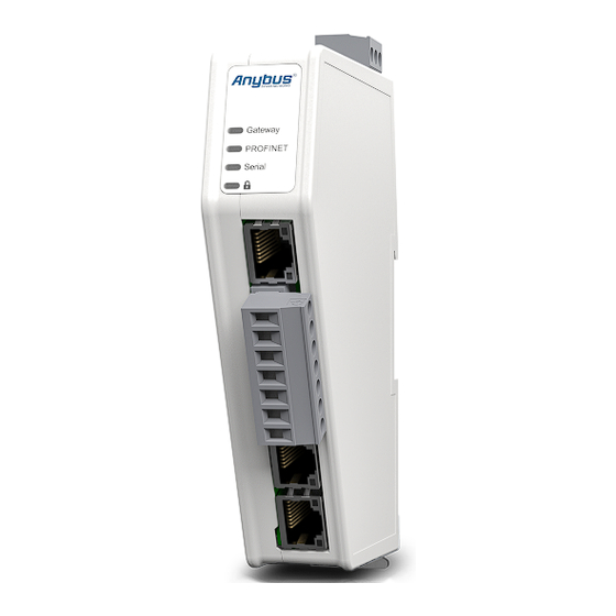
® ™ Anybus Communicator - PROFINET to Modbus Installation RTU/Serial 5. Installation 5.1. DIN Rail Mounting IMPORTANT The equipment must be electrically grounded through the DIN rail for EMC compliance. Make sure that the equipment is correctly mounted on the rail and that the rail is properly grounded. - Page 11 ® ™ Connector Port Guide Anybus Communicator - PROFINET to Modbus RTU/Serial 5.2. Connector Port Guide Figure 2. Communicator connector ports Position Port Number Connector Port Usage Ethernet Configuration port Serial Serial RS-232/485 Device X2.1 Ethernet PROFINET network X2.2 Ethernet PROFINET network SP2954 Version 1.12 Page 9 of 28...
- Page 12 ® ™ Anybus Communicator - PROFINET to Modbus Connect to PROFINET Network RTU/Serial 5.3. Connect to PROFINET Network Figure 3. Connect to PROFINET network RJ45 Connector Description Not used Not used Not used Not used Page 10 of 28 SP2954 Version 1.12...
- Page 13 ® ™ Connect to Serial RS232/RS485 Subnetwork Anybus Communicator - PROFINET to Modbus RTU/Serial 5.4. Connect to Serial RS232/RS485 Subnetwork NOTE Use minimum 90 oC copper (Cu) wire only. Figure 4. Connect to serial RS232/RS485 subnetwork SP2954 Version 1.12 Page 11 of 28...
- Page 14 ® ™ Anybus Communicator - PROFINET to Modbus Connect to Serial RS232/RS485 Subnetwork RTU/Serial 7-pin connector Signal +5 V OUT RS485+ A RS485- B Signal GND Functional Earth (FE) RS232 Tx Transmit Data RS232 Rx Receive Data Page 12 of 28 SP2954 Version 1.12...
-
Page 15: Connect To Power
® ™ Connect to Power Anybus Communicator - PROFINET to Modbus RTU/Serial 5.5. Connect to Power CAUTION Ensure that the power supply is turned off before connecting it to the equipment. IMPORTANT Using the wrong type of power supply can damage the equipment. Ensure that the power supply is connected properly and of the recommended type. -
Page 16: Power Connector Pinout
® ™ Anybus Communicator - PROFINET to Modbus Connect to Power RTU/Serial Power Connector Pinout Power port Description 12-30 VDC Power Connector Ground (GND) Functional Earth (FE) Page 14 of 28 SP2954 Version 1.12... -
Page 17: Security Switch
® ™ Security Switch Anybus Communicator - PROFINET to Modbus RTU/Serial 5.6. Security Switch IMPORTANT After completing the configuration of the Communicator, lock the security switch to prevent unauthorized access to the Communicator built-in web interface. When the security switch is in its locked position, the Communicator built-in web interface cannot be accessed, and the Communicator cannot be configured using the built-in web interface. - Page 18 ® ™ Anybus Communicator - PROFINET to Modbus Security Switch RTU/Serial Use a pointed object, such as a ballpoint pen. • To lock the security switch, push the toggle towards the Communicator front. • To unlock the security switch, push the toggle towards the Communicator back. Security Switch Status LED Figure 7.
- Page 19 ® ™ Lock the Cables Anybus Communicator - PROFINET to Modbus RTU/Serial 5.7. Lock the Cables Figure 8. Lock the cables To strain relieve the cables, place a cable tie in the holder and lock the cables. SP2954 Version 1.12 Page 17 of 28...
- Page 20 ® ™ Anybus Communicator - PROFINET to Modbus DIN Rail Demount RTU/Serial 5.8. DIN Rail Demount Before You Begin IMPORTANT Be careful when removing the Communicator from the DIN-rail. If not removed properly, the DIN rail locking mechanism and the product cover can break.
- Page 21 ® ™ DIN Rail Demount Anybus Communicator - PROFINET to Modbus RTU/Serial Hold the screwdriver in the DIN rail locking mechanism while you unhook the Communicator from the DIN rail. Figure 10. Unhook the Communicator SP2954 Version 1.12 Page 19 of 28...
- Page 22 ® ™ Anybus Communicator - PROFINET to Modbus Configuration RTU/Serial 6. Configuration 6.1. Connect to PC and Power Figure 11. Connect to PC and Power Page 20 of 28 SP2954 Version 1.12...
- Page 23 ® ™ Find the Communicator on Your PC Anybus Communicator - PROFINET to Modbus RTU/Serial 6.2. Find the Communicator on Your PC The Communicator default IP address is 192.168.0.10. To be able to access the Communicator built-in web interface you may need to adjust the IP settings, choose one of the following methods: Option 1 | Set a static IP address on the PC On the PC accessing the Communicator built-in web interface,...
- Page 24 ® ™ Anybus Communicator - PROFINET to Modbus Configure the Communicator RTU/Serial 6.3. Configure the Communicator Figure 12. The Communicator built-in web interface Home page Open the Communicator built-in web interface in HMS IPconfig or enter the Communicator IP address in your web browser. The built-in web interface takes you through the steps to configure the Communicator.
- Page 25 ® ™ Configure the Communicator Anybus Communicator - PROFINET to Modbus RTU/Serial Support and Resources If you need more in-depth information about the configuration, please visit www.anybus.com/support and enter the product article number to search for the Communicator support web page. You find the product article number on the product cover.
-
Page 26: Technical Data
® ™ Anybus Communicator - PROFINET to Modbus Technical Data RTU/Serial 7. Technical Data For complete technical specifications and regulatory compliance information, please visit www.anybus.com. 7.1. Technical Specifications Article identification ABC3013 Configuration connector RJ45 Communication connector RJ45 x 2 Serial connector 7-pin screw connector Power connector 3-pin screw connector... - Page 27 ® ™ Communicator LED Indicators Anybus Communicator - PROFINET to Modbus RTU/Serial 8. Communicator LED Indicators NOTE Before you can verify operation, you must configure the Communicator. Figure 13. Communicator status (A), High level Network/Client (B), Subnetwork 2 (C) and (D) Security Switch LED A LED B...
- Page 28 ® ™ Anybus Communicator - PROFINET to Modbus Fatal Error and Exception Error RTU/Serial LED A LED B LED C LED D Operation Gateway status PROFINET Slave Subnetwork Security switch status Green, one Startup phase Connection with IO Running, one or more flash controller establish IO nodes are offline...
-
Page 29: Ethernet Led Indicators
® ™ Ethernet LED Indicators Anybus Communicator - PROFINET to Modbus RTU/Serial 9. Ethernet LED Indicators Figure 14. LED A. Activity LED B. Not used LED A Function No link (or no power) Green Link (100 Mbit/s) established Green, flashing Activity (100 Mbit/s) Yellow Link (10 Mbit/s) established... - Page 30 This page is intentionally left blank.
Need help?
Do you have a question about the Anybus Communicator SP2954 and is the answer not in the manual?
Questions and answers