
Subscribe to Our Youtube Channel
Related Manuals for HMS Networks Anybus ABC3007-A


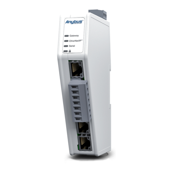
Summary of Contents for HMS Networks Anybus ABC3007-A
- Page 1 ® ™ Anybus Communicator ™ EtherNet/IP to Modbus RTU STARTUP GUIDE SP2791 1.1 en-US ENGLISH...
-
Page 2: Important User Information
HMS Networks reserves the right to modify its products in line with its policy of continuous product development. The information in this document shall therefore not be construed as a commitment on the part of HMS Networks and is subject to change without notice. -
Page 3: About This Document
Preface 3 (26) Preface About This Document This manual describes the installation of Anybus Communicator. For information on how to configure the Anybus Communicator, refer to the user manual. For additional documentation and software downloads, FAQs, troubleshooting guides and technical support, please visit www.anybus.com/support. ®... -
Page 4: Document Conventions
Preface 4 (26) Document Conventions Numbered lists indicate tasks that should be carried out in sequence: First do this Then do this Bulleted lists are used for: • Tasks that can be carried out in any order • Itemized information ►... - Page 5 Preface 5 (26) Trademarks ® Anybus is a registered trademark of HMS Networks AB. All other trademarks are the property of their respective holders. ® ™ SP2791 1.1 en-US Anybus Communicator Startup Guide...
-
Page 6: Intended Use
Safety 6 (26) Safety Intended Use The intended use of this equipment is as a communication interface and gateway. The equipment receives and transmits data on various physical layers and connection types. If this equipment is used in a manner not specified by the manufacturer, the protection provided by the equipment may be impaired. - Page 7 Preparation 7 (26) Preparation Cabling Have the following cables available: • Ethernet cable for configuration • Ethernet cable for connecting to the high level network • Power cable Tools Have the following tools available: • Flat-head screwdriver, size 5.5 mm Needed when removing the Communicator from DIN-rail.
- Page 8 Preparation 8 (26) Support and Resources For additional documentation and software downloads, FAQs, troubleshooting guides and technical support, please scan the QR code to visit the Communicator support web page. You can also visit www.anybus.com/support and enter the product article number to search for the Communicator support web page.
-
Page 9: Installation
Installation 9 (26) Installation DIN Rail Mounting The equipment must be electrically grounded through the DIN rail for EMC compliance. Make sure that the equipment is correctly mounted on the rail and that the rail is properly grounded. Attach the Communicator on the DIN rail. ®... - Page 10 Installation 10 (26) Connecting to EtherNet/IP Network EtherNet/IP Connector Description ® ™ SP2791 1.1 en-US Anybus Communicator Startup Guide...
- Page 11 Installation 11 (26) Connecting to Serial RS232/RS485 Subnetwork Use minimum 90 oC copper (Cu) wire only. 7-pin connector Signal +5 V OUT RS485- A RS485+ B Signal GND Functional Earth (FE) RS232 Tx Output RS232 Rx Input ® ™ SP2791 1.1 en-US Anybus Communicator Startup Guide...
-
Page 12: Connecting To Power
Installation 12 (26) Connecting to Power Caution Ensure that the power supply is turned off before connecting it to the equipment. Using the wrong type of power supply can damage the equipment. Ensure that the power supply is connected properly and of the recommended type. -
Page 13: Security Switch
Installation 13 (26) Security Switch After completing the configuration of the Communicator, lock the security switch to prevent unauthorized access to the Communicator built-in web interface. When the security switch is in its locked position, the Communicator built-in web interface can not be accessed and the Communicator can not be configured. - Page 14 Installation 14 (26) Security Switch Status LED When the security switch is in its: • locked position, the security switch status LED turn solid green. • unlocked position, the security switch status LED is turned off. ® ™ SP2791 1.1 en-US Anybus Communicator Startup Guide...
- Page 15 Installation 15 (26) Locking the Cables To strain relieve the cables, place a cable tie in the holder and lock the cables. ® ™ SP2791 1.1 en-US Anybus Communicator Startup Guide...
- Page 16 Installation 16 (26) DIN Rail Demount Before You Begin Be careful when removing the Communicator from the DIN-rail. If not removed properly, the DIN rail locking mechanism and the product cover can break. Have a flat-blade screwdriver, size 5.5 mm, available. Procedure Remove the Communicator from the DIN Rail: Insert the screwdriver into the Communicator DIN rail locking mechanism.
- Page 17 Installation 17 (26) Hold the screwdriver in the DIN rail locking mechanism while you unhook the Communicator from the DIN rail. ® ™ SP2791 1.1 en-US Anybus Communicator Startup Guide...
- Page 18 Configuration 18 (26) Configuration Connecting to PC and power Connect an Ethernet cable between the Communicator configuration port and your PC. Connect the Communicator to a power supply. ® ™ SP2791 1.1 en-US Anybus Communicator Startup Guide...
- Page 19 Configuration 19 (26) Finding the Communicator on Your PC The Communicator default IP address is 192.168.0.10. To be able to access the Communicator built-in web interface: Option 1 | Set a static IP address on the PC On the PC accessing the Communicator built-in web interface, set a static IP address within the same IP address range as the Communicator IP address.
- Page 20 Configuration 20 (26) Configuring the Communicator Open the Communicator built-in web interface in HMS IPconfig or enter the Communicator IP address in your web browser. The built-in web interface takes you through the steps to configure the Communicator. Support and Resources If you need more in-depth information about the configuration, please visit www.anybus.com/support and enter the product article number to search for...
-
Page 21: Technical Data
Technical Data 21 (26) Technical Data Technical Specifications ABC3007-A Article identification Communication RJ45 x 2 connector Configuration RJ45 connector 7-pin screw connector Serial connector Power connector 3-pin screw connector 12-30 VDC Power supply Reverse voltage protection and short circuit protection Power consumption Typical: 160 mA @ 24 V Max: 400 mA @ 12 V... - Page 22 This page intentionally left blank...
- Page 23 Appendix A: Communicator LED Indicators 23 (26) Communicator LED Indicators Before you can verify operation you must configure the Communicator. LED A LED B LED C LED D Operation Gateway Subnetwork Security switch EtherNet/IP - status Status Adapter No power No power/ No power/ No power/...
- Page 24 Appendix A: Communicator LED Indicators 24 (26) LED A LED B LED C LED D Operation Gateway Subnetwork Security switch EtherNet/IP - Status status Adapter Duplicated Fatal error Exception/ Fatal error EtherNet IP address/Fatal error One or more Red, flashing Invalid All nodes are connections...
-
Page 25: Ethernet Led Indicators
Appendix B: Ethernet LED Indicators 25 (26) Ethernet LED Indicators LED A Function No link (or no power) Green Link (100 Mbit/s) established Green, flashing Activity (100 Mbit/s) Yellow Link (10 Mbit/s) established Yellow, flashing Activity (10 Mbit/s) LED B Function Not used ®... - Page 26 last page © 2020 HMS Industrial Networks Box 4126 300 04 Halmstad, Sweden info@hms.se SP2791 1.1 en-US / 2020-09-21 / 19954...
Need help?
Do you have a question about the Anybus ABC3007-A and is the answer not in the manual?
Questions and answers