Table of Contents
Advertisement
Quick Links
Advertisement
Table of Contents

Related Manuals for thomann BOTEX DMX DC-192


Summary of Contents for thomann BOTEX DMX DC-192
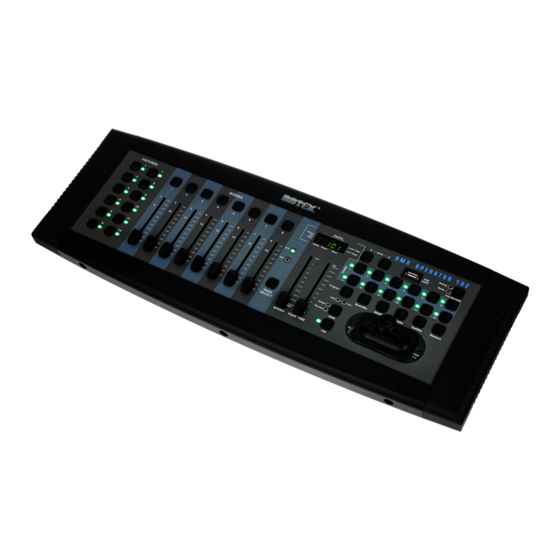
- Page 1 DMX DC-192 DMX Controller...
- Page 2 Thomann GmbH Hans-Thomann-Straße 1 96138 Burgebrach Germany Telephone: +49 (0) 9546 9223-0 Internet: www.thomann.de 11.01.2024, ID: 391103 (V4)
-
Page 3: Table Of Contents
Table of contents Table of contents General information..........................6 1.1 Symbols and signal words....................... 6 Safety instructions............................. 8 Features............................... 10 Installation..............................11 Starting up..............................13 Connections and controls........................14 Basics................................18 Operating..............................21 8.1 Manual operation..........................21 8.2 Joystick settings..........................21 8.3 Scenes.............................. - Page 4 Table of contents Protecting the environment......................42 DMX DC-192 DMX Controller...
- Page 5 DMX DC-192 DMX Controller...
-
Page 6: General Information
Our products and documentation are subject to a process of continuous development. They are therefore subject to change. Please refer to the latest version of the documentation, which is ready for download under www.thomann.de. 1.1 Symbols and signal words In this section you will find an overview of the meaning of symbols and signal words that are used in this document. - Page 7 General information Warning signs Type of danger Warning – danger zone. DMX DC-192 DMX Controller...
-
Page 8: Safety Instructions
Safety instructions Safety instructions Intended use This device is used to control spotlights, dimmers, lighting effects equipment, Moving Heads or other DMX-controlled devices. The device is designed for professional use and is not suit‐ able for use in households. Use the device only as described in this user manual. Any other use or use under other operating conditions is considered to be improper and may result in per‐... - Page 9 Safety instructions NOTICE! Damage to the external power supply due to high voltages! The device is powered by an external power supply. The external power supply can be damaged if it is operated with the incorrect voltage or if high voltage peaks occur. In the worst case, excess voltages can also cause a risk of injury and fires. Make sure that the voltage specification on the external power supply matches the local power grid before plugging in the power supply.
-
Page 10: Features
Features Features Special features of the device: 192 DMX channels Twelve devices with up to 16 DMX channels can be operated Connection for a fog machine 30 banks with eight freely programmable scenes Twelve programmable chases Eight faders for manual control Joystick for controlling the PAN and TILT movement Reverse Joystick function Fine tuning for PAN and TILT... -
Page 11: Installation
Installation Installation NOTICE! Possible staining due to plasticiser in rubber feet! The plasticiser contained in the rubber feet of this product may react with the coating of the floor and cause permanent dark stains after some time. If necessary, use a suitable mat or felt slide to prevent direct contact between the device’s rubber feet and the floor. - Page 12 Installation Wiring diagram for fog machines READY MACHINE HEATING DMX DC-192 DMX Controller...
-
Page 13: Starting Up
Starting up Starting up Create all connections while the device is off. Use the shortest possible high-quality cables for all connections. Take care when running the cables to prevent tripping hazards. Connecting the power adapter Connect the included power adapter to the 9V connector of the unit and then plug the power adapter into a wall outlet. -
Page 14: Connections And Controls
Connections and controls Connections and controls Front ö & FIXTURES SCENES PORT FOG MACHINE << << Program Music/Bkc Midi/Rec Auto/Del Tap/Disp Blackout TILT PAGE SELECT MODE TILT SPEED FADE TIME FINE DMX DC-192 DMX Controller... - Page 15 Connections and controls 1 [FIXTURES] | For selecting the devices relevant for the control 2 [SCENES] | Used to store and play back programmed scenes. 3 Display. The LED display shows you relevant information depending on the respective operation. 4 [Bank] / [Bank] | Buttons for selecting a scene bank or a chase step.
- Page 16 Connections and controls 11 [FINE] | Used in conjunction with the joystick. When the button is pressed, a certain area can be controlled much more precisely with the scanner or the moving light. 12 [FADE TIME] | Fader for adjusting the chase fade time (0 … 30 seconds) 13 [SPEED] | Fader for adjusting the chase speed (0.1 seconds …...
- Page 17 Connections and controls Back MIDI AUDIO In DB-9 MIDI In MIDI Out FOG Machine DMX Out DC In POWER ö & 1 [USB] | USB connection socket 2 MIDI / DMX operation switch 3 [AUDIO In] | Cinch input socket for connecting audio devices for sound control 4 [DB-9] | For connecting an optional chase step controller 5 [MIDI In] | MIDI input socket 6 [MIDI Out] | MIDI output socket...
-
Page 18: Basics
Basics Basics This chapter provides basic information about the data transmission using the DMX protocol. Signal transmission DMX signals are generated by a DMX controller. The signals are transferred over a DMX cable to the connected devices. Each connection can transmit up to 512 channels. For each channel, a value between 0 and 255 is being transmitted. - Page 19 Basics If the cable length exceeds 300 m (328 yds.) or the number of devices is greater than 32, the signal must be amplified using a DMX booster. Signal processing Each DMX devices operates on a specific number of channels to transfer the incoming control signals into movements, changing of light intensity or colour, and so on.
- Page 20 Basics It is no problem to use a start address more than once in a DMX chain. In that case, the relevant receivers operate synchronously (identical movement, light intensity, colour, and so on). Addressing When setting the DMX address, the counting method of the device determines the first channel.
-
Page 21: Operating
Operating Operating 8.1 Manual operation When you turn on the controller, it starts by default in Manual / Blackout mode. All output values are blanked out. To show the values, press [Blackout]. To determine the respective blackout status, there is an indicator in the display that flashes when activated and shows ‘OFF’... - Page 22 Operating Press [Tap/Disp] to switch between ‘PL.XX’ and ‘PH.XX’ . ‘PL.XX’ stands for the low byte or fine channel, generally listed as the Pan Fine channel. ‘PL.XX’ stands for the high byte or rough channel, generally listed as the Pan channel. Set ‘PH.XX’ , press and hold [MODE] and then press the [SCENE] button corresponding to the device's pan channel.
- Page 23 Operating Assigning the reverse joystick Keep [Program] pressed for about two seconds or until the PROG indicator flashes on the (pan / tilt reversal) display. When the indicator flashes, the recording mode is active and you can release the button. Keep [MODE] pressed and press [FINE].
- Page 24 Operating Press [Bank] / [Bank] to switch between ‘TL.XX’ and ‘TH.XX’ . ‘TL.XX’ stands for the low byte or fine channel, generally listed as the Tilt Fine channel. ‘TH.XX’ stands for the high byte or rough channel, generally listed as the Tilt channel. Set ‘TH.XX’ , press and hold [MODE] and then press the [SCENE] button corresponding to the device's tilt channel.
-
Page 25: Scenes
Operating Deletion Pan / Tilt joystick set‐ Turn off the controller using the mains switch. tings on all devices Simultaneously press [Auto/Del] and [MODE] and switch the controller back on again. All LEDs flash three times, the settings have been cleared. 8.3 Scenes 8.3.1 Recording scenes Keep [Program] pressed for about two seconds or until the PROG indicator flashes on the... - Page 26 Operating Press one of the [SCENE] buttons (1 to 8) to store. As soon as all the LEDs flash, the scene is saved. Make sure you use a different button each time you save a scene so you do not overwrite what you want to keep.
- Page 27 Operating Keep [Program] pressed for about two seconds or until the PROG indicator stops flashing on the display. As soon as the blackout indicator flashes, the programme mode is deacti‐ vated. 8.3.3 Copying a scene Keep [Program] pressed for about two seconds or until the PROG indicator flashes on the display.
- Page 28 Operating 8.3.4 Deleting a scene Keep [Program] pressed for about two seconds or until the PROG indicator flashes on the display. When the indicator flashes, the recording mode is active and you can release the button. Use [Bank] / [Bank] to select the scene bank that contains the scene you want to delete.
- Page 29 Operating 8.3.6 Scene playback Manual playback When you turn on the controller, it starts by default in Manual / Blackout mode. All output values are blanked out. To show the values, press [Blackout]. To determine the respective blackout status, there is an indicator in the display that flashes when acti‐ vated and shows ‘OFF’...
-
Page 30: Chases
Operating 8.3.7 Audio playback Press [Music/Bkc]. The indicator for automatic playback in the display lights up. Press [Bank] / [Bank] to select a desired scene bank (1 to 30) or press a [CHASE] button (1 to 12). The selected scene bank or chase will start synchronously with the audio playback of the internal microphone or the connected line level input. - Page 31 Operating Press [Midi/Rec] to record the chase step. When the chase step is recorded, all LEDs flash three times. Repeat steps 3 and 4 to record further steps. Keep [Program] pressed for about two seconds or until the PROG indicator stops flashing on the display.
- Page 32 Operating 8.4.3 Editing chases Adding a chase step Keep [Program] pressed for about two seconds or until the PROG indicator flashes on the display. When the indicator flashes, the recording mode is active and you can release the button. To select a chase press the corresponding [CHASE] button (1 to 12). The corresponding LED lights up.
- Page 33 Operating Deleting chase steps Keep [Program] pressed for about two seconds or until the PROG indicator flashes on the display. When the indicator flashes, the recording mode is active and you can release the button. To select a chase press the corresponding [CHASE] button (1 to 12). The corresponding LED lights up.
- Page 34 Operating Repeat steps 2 and 3 to delete further chases. Keep [Program] pressed for about two seconds or until the PROG indicator stops flashing on the display. As soon as the blackout indicator flashes, the programme mode is deacti‐ vated. Deleting all chases Turn off the controller using the mains switch.
- Page 35 Operating Automatic playback Press [Auto/Del]. The indicator for automatic playback in the display lights up. Press the [CHASE] buttons of the chases you want to play. The corresponding LED lights up and playback starts. You can choose more than one chase at a time to create a chase sequence.
-
Page 36: Copying Scene Bank And Fixtures
Operating 8.5 Copying scene bank and fixtures 8.5.1 Copying scene bank Start programme mode. Use [Bank] / [Bank] to select the scene bank you what to copy. Press [Midi/Rec] and then use [Bank] / [Bank] to select the scene bank you what to copy to. -
Page 37: Fade Time
Operating 8.6 Fade time Press [MODE] and then [Tap/Disp]. The display now shows ‘ONLY’ or ‘ALL’ for 3 seconds, depending on the current settings. ‘ONLY’ indicates that only the pan / tilt channels are controlled by the [FADE TIME] fader. ‘ALL’ indicates that all channels are changed by the fader. - Page 38 Operating Control This unit can receive MIDI data to control or activate scene banks 1 to 30, chases 1 to 12, and the blackout function. Note number Function 00 to 11 Turning chases 1 … 12 on / off 12 to 19 Turning scenes 1 …...
-
Page 39: Technical Specifications
Technical specifications Technical specifications Control protocols DMX512 Number of DMX channels max. 192 Input connections MIDI DIN socket, 5-pin Audio signal Cinch socket, 100 mV, 1 Vpp Power supply Panel socket for power adapter Chase step controller D-sub panel socket, 9-pin Output connections DMX control XLR panel socket, 3-pin... - Page 40 Technical specifications Ambient conditions Temperature range 0 °C…40 °C Relative humidity 50% (non-condensing) Further information Preset function External storage option DMX universes Ethernet DMX DC-192 DMX Controller...
-
Page 41: Plug And Connection Assignment
Plug and connection assignment Plug and connection assignment Introduction This chapter will help you select the right cables and plugs to connect your valuable equip‐ ment so that a perfect light experience is guaranteed. Please take our tips, because especially in ‘Sound & Light’ caution is indicated: Even if a plug fits into a socket, the result of an incorrect connection may be a destroyed DMX controller, a short circuit or ‘just’... - Page 42 Protecting the environment Protecting the environment Disposal of the packing material Environmentally friendly materials have been chosen for the packaging. These materials can be sent for normal recycling. Ensure that plastic bags, packaging, etc. are disposed of in the proper manner. Do not dispose of these materials with your normal household waste, but make sure that they are collected for recycling.
- Page 43 Repairing a device or passing it on to another user is an ecologically valuable alternative to disposal. You can return your old device to Thomann GmbH at no charge. Check the current conditions on www.thomann.de. If your old device contains personal data, delete those data before disposing of it.
- Page 44 Notes DMX DC-192 DMX Controller...
- Page 45 Notes DMX DC-192 DMX Controller...
- Page 46 Notes DMX DC-192 DMX Controller...
- Page 48 Musikhaus Thomann · Hans-Thomann-Straße 1 · 96138 Burgebrach · Germany · www.thomann.de...
Need help?
Do you have a question about the BOTEX DMX DC-192 and is the answer not in the manual?
Questions and answers