
Related Manuals for SST Automation GT200-BM-RS


Summary of Contents for SST Automation GT200-BM-RS
- Page 1 Modbus / BACnet IP Gateway GT200-BM-RS/2RS User Manual V 1.5 SST Automation E-mail: SUPPORT@SSTAUTOMATION.COM WWW.SSTCOMM.COM...
- Page 2 The product has many applications. The users must make sure that all operations and results are in accordance with the safety of relevant fields, and the safety includes laws, rules, codes and standards. Copyright Copyright © 2022 by SST Automation. All rights reserved. Trademark is the registered trade mark of SST Automation.
-
Page 3: Table Of Contents
Catalog 1 Product Overview ..............................1 1.1 Product Function ............................1 1.2 Product Features ............................. 1 1.3 Technical Specifications ..........................1 1.4 Revision History .............................2 2 Hardware Descriptions .............................. 3 2.1 Product Appearance ............................3 2.2 LED Indicators ............................... 4 2.3 Configuration Switch ............................. 4 2.4 Interfaces ................................ -
Page 4: Product Overview
GT200-BM Series include two gateways: Number of Serial Interfaces GT200-BM-RS One RS-485 interface GT200-BM-2RS Two RS-485 interfaces Note: This manual applies to GT200-BM-2RS of V1.4/1.5 and GT200-BM-RS of V1.4/1.5. 1.2 Product Features Redundant power supply. RS485 interface(s) with 1KV optical isolation. ... -
Page 5: Revision History
[9] Operating temperature: -4°F to 140°F (-20ºC to 60 ºC), relative humidity: 5% ~ 95% (non-condensing). [10] External dimension (W*H*D): GT200-BM-2RS: 1.33in*4.56in*4.21in (34mm*116mm*107mm). GT200-BM-RS: 1.6 in*5.0in*4.4in (40 mm*125mm*110mm). [11] Installation: 35mm DIN rail. [12] Protection class: IP20. [13] Test standard: EMC test standards. -
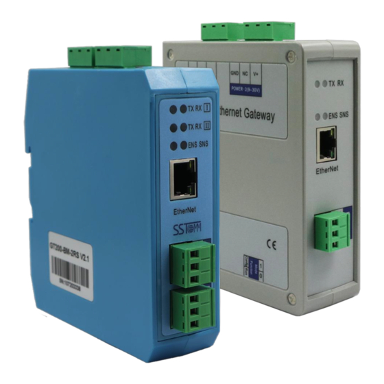
Page 6: Hardware Descriptions
2 Hardware Descriptions 2.1 Product Appearance GT200-BM-RS Dual Power Interfaces Serial II Indicators Ethernet Indicators Ethernet Interface RS-485 Interface I Configuration Switch GT200-BM-2RS Dual Power Interfaces Serial I Indicators Serial II Indicators Ethernet Interface Ethernet Indicators RS-485 Interface I RS-485 Interface II Configuration Switch Note: This picture is for reference only. -
Page 7: Led Indicators
2.2 LED Indicators Indicators State Description Green On IP address with no confliction Red On IP address with confliction Red Blinking DHCP, BOOTP, IP address conflict detection Green On BACnet IP interface data is received or transmitted Green Blinking BACnet IP interface data is not received or transmitted Simultaneously On At the power ENS&SNS... -
Page 8: Interfaces
2.4 Interfaces 2.4.1 Power Interface Two power interfaces with a power redundancy function. When one of the power supplies lose power, the other power supply will continuously power the gateway. 24V+ Description NC (Not Connected) 24V+, DC Notes: Connecting the second power supply is optional as it offers redundancy. 2.4.2 Ethernet Interface Ethernet interface is a RJ-45 connector, 10/100M adaptive. -
Page 9: Rs-485 Interface
2.4.3 RS-485 Interface GT200-BM series support standard RS-485 interface Description B+, connected to RS-485 D+ A-, connected to RS-485 D- Note: When communicating in RS485 interfaces, in order to prevent the reflection and interference of the signal, it’s recommended to connect a terminal resistor (120Ohm, 1/2W) parallel with the communication wires at both farthest ends of the network. -
Page 10: Hardware Installation
3 Hardware Installation 3.1 Mechanical Dimension Size (width * height * depth): GT200-BM-2RS Size: 1.33in * 4.56in * 4.21in (34mm * 116mm * 107.4mm) WWW.SSTAUTOMATION.COM... - Page 11 GT200-BM-RS size: 1.6 in * 5.0 in * 4.4 in (40 mm * 125 mm * 110 mm) WWW.SSTAUTOMATION.COM...
-
Page 12: Installation Method
3.2 Installation Method Using 1.38 in (35 mm) DIN RAIL. Install the gateway Uninstall the gateway 1. Use a screwdriver to pass through the DIN RAIL bar, pull down and hold. 2. Pull out the gateway. 3. Lift up the gateway. ③... -
Page 13: How To Start
4 How to Start 4.1 Hardware Connection Connect the power to the power supply. Please do not power on the devices before finishing and confirming all the connections. Optional: Connect power supply II for backup redundancy. Connect Modbus serial devices using the RS-485 interfaces. 485+ 485- RS485 device... -
Page 14: Software Configuration
How to Use the Ping Command. This is a default configuration created by SST Automation. If you would like to create a configuration from the beginning simply click “New”. Click “BACnet IP Server” under the Device Window and configure the settings to your needs under the Configuration Window. -
Page 15: Software Instructions
255.255.255.0 and the gateway address is 192.168.0.1. 5.1 Notes before Configuration SST-BM-CFG is a product based on Windows platform, and used to configure parameters of GT200-BM-RS and GT200-BM-2RS gateways. Please make sure the user's computer and the GT200-BM gateways are in the same network segment before you run the software. -
Page 16: Search Equipment
5.2 Search Equipment Before configuring parameters, the user will need to search for the gateway using the software. The software provides two ways to search the gateway for the user. 5.2.1 Search All Equipment of Ethernet Click "Search equipment" button of the main interface and the software will search all of the available devices and list them in the main interface. -
Page 17: Configuration
After entering the correct IP address, the software will search GT200-BM gateway with this IP address in the network, and list the information of the equipment in the main interface. Note: If the users select the "IP search", users need to enter correct IP address or it will not get any devices. 5.3 Configuration Select the equipment to be configured in the list, and the function like "Locate", "Configuration", "Remote Reset", "Import"... -
Page 18: Configure Ethernet Parameters
Click "Configuration" button will pop up the window: 5.3.1 Configure Ethernet Parameters Note: The gray parts cannot be changed. Ethernet parameters include: "Device Name", "Assign IP Mode", "IP Address", "Subnet Mask", "Default Gateway", "DNS1", "DNS2". WWW.SSTAUTOMATION.COM... -
Page 19: Configure Serial And Modbus Parameters
Device Name: Enter a name used to identify the device in order to distinguish from other devices. Note: The name cannot have spaces, up to 16 characters. Assign IP Mode: Set the IP address assign mode of the device. IP address: Set the IP address of the device. Subnet Mask: Set the subnet mask of the device. - Page 20 Baud Rate: 1200, 2400, 4800, 9600, 19200, 38400, 57600, 115200, 230400. Data Bits: 8 (currently only support 8 data bits). Check Bit: None, Odd, Even, Mark, Space. Stop Bits: 1, 2. Transmission mode: RTU. Response timeout: When the Modbus master send commands, the time waiting for response from the slave, the range is 300~60000ms.
-
Page 21: Command Configuration
Auto Demotion Time: When the Demotion Time timeout the command will promote a fast command. The range of the parameter value is 3000 to 600000ms. How to action after N successive response timeout: Clear Data. Hold Data 5.3.3 Command Configuration Add and delete nodes. - Page 22 For each Modbus commands' setting, SST-BM-CFG will automatically map the Modbus commands to the corresponding BACnet objects after configuring. Read coil Status: fill in the number of data, automatically mapped to BACnet BI (binary input). Take above picture as an example. Read input status: mapped to BACnet BI (binary input).
-
Page 23: Locate
Object type: AI and MI optional, default is AI. Object Name: Editable, the maximum data length supported is 12. Register Count: 1 and 2 optional, default is 1 (Map one Modbus register to a BACnet object). Data Types: BOOL, INT16 (signed 16-bit integer data), UINT16 (unsigned 16-bit integer data), INT32 (signed 32-bit integer data), INT32V (INT32 Inverse, contrary to high and low word INT32), UINT32 (unsigned 32-bit integer data), UINT32V (UINT32 Inverse, contrary to high and low word of UINT32), Float, and FloatV (Float Inverse, contrary to high and low word of Float) optional ( different display for different types of BACnet object). -
Page 24: Remote Reset
5.5 Remote Reset The function of "remote reset" is restarting the selected device. Select the equipment in the list first, click "Remote reset" button, it will pop up a confirmation dialog, then click "OK" to complete the operation. WWW.SSTAUTOMATION.COM... -
Page 25: Open And Save Configuration
5.6 Open and Save Configuration Open the configuration: open and display the configuration data which is saved on the computer. Export to Excel: the configuration parameters are saved to the computer (xls), one-to-one mapping relationship of each Modbus command and BACnet objects. They can easily be seen from the export of Excel. Save: save the configuration parameters to a computer (. - Page 26 WWW.SSTAUTOMATION.COM...
-
Page 27: Typical Application
6 Typical Application GT200-BM gateway can connect Modbus slave devices to BACnet IP network. GT200-BM gateway is a bridge in the communication network and implements the conversation between BACnet IP and Modbus RTU. The following is the typical application of GT200-BM-2RS. The above chart multi-function energy monitoring instrument is a current measuring meter with Modbus slave station interface, the measurement of the current value is stored in the address 40001.
Need help?
Do you have a question about the GT200-BM-RS and is the answer not in the manual?
Questions and answers