Emerson Rosemount 3051S Quick Start Manual
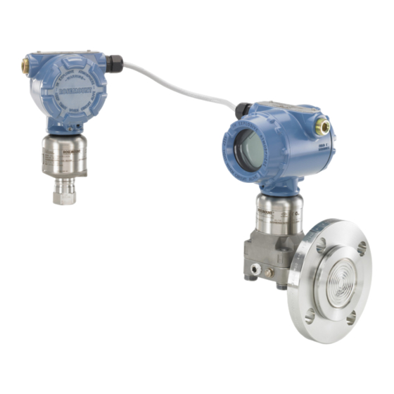
Electronic remote
sensor system
Hide thumbs
Also See for Rosemount 3051S:
- Reference manual (240 pages) ,
- Manual (96 pages) ,
- Quick start manual (60 pages)

Related Manuals for Emerson Rosemount 3051S


Summary of Contents for Emerson Rosemount 3051S
- Page 1 Quick Start Guide 00825-0100-4804, Rev BC August 2016 Rosemount 3051S Electronic Remote )™ Sensor (ERS System ® with HART Protocol...
-
Page 2: Table Of Contents
August 2016 Quick Start Guide NOTICE This guide provides basic guidelines for the Rosemount 3051S ERS System. It does not provide instructions for diagnostics, maintenance, service, or troubleshooting. Refer to the Rosemount 3051S ERS Reference Manual for more instruction. This document is also available electronically on EmersonProcess.com/Rosemount. -
Page 3: Identify All Rosemount 3051S Ers System
(P ) process connection. An optional remote display and interface may also be included (not pictured) if ordered. 1. Look at the wire-on tag on the Rosemount 3051S sensor to identify whether it is configured as the P or P sensor. - Page 4 2.2 Horizontal installation In a horizontal installation, the P sensor should be installed at the upstream process connection. The P sensor should be installed downstream. Figure 2. Horizontal Rosemount 3051S ERS Installation P sensor P sensor Pressure drop 2.3 Mounting bracket Figure 3.
- Page 5 If the installation requires assembly of a process flange, manifold, or flange adaptors, follow these assembly guidelines to ensure a tight seal for optimal performance characteristics of the Rosemount 3051S ERS System. Only use bolts ™ supplied with the transmitter or sold by Emerson Process Management as spare parts.
-
Page 6: Consider Housing Rotation
August 2016 Quick Start Guide Figure 5. Module Isolator Plate A. Bolt C. Coplanar flange B. Sensor module isolator plate D. Flange adapters Table 1. Torque Values for the Flange and Flange Adapters Bolts Bolt material Head markings Initial torque Final torque Carbon Steel (CS) 300 in-lb... -
Page 7: Set Switches
4.0 Set switches If the Rosemount 3051S ERS sensor is equipped with alarm and security hardware switches, verify the desired configuration (default: alarm = HI, security = OFF). 1. If the sensor is installed, secure the loop and remove power. -
Page 8: Wiring Diagrams
The wiring connection between the sensors (and remote housing if applicable) must be made directly. An intrinsically safe barrier or other high-impedance device will cause the Rosemount 3051S ERS System to malfunction if placed in between any of the Rosemount 3051S ERS sensors. - Page 9 Quick Start Guide August 2016 Figure 8. Wiring Diagram for Standard Rosemount 3051S ERS System...
- Page 10 August 2016 Quick Start Guide Figure 9. Wiring Diagram for Rosemount 3051S ERS System with Remote Display in “Tree” Configuration...
- Page 11 Quick Start Guide August 2016 Figure 10. Wiring Diagram for Rosemount 3051S ERS System with Remote Display in “Daisy-Chain” Configuration...
- Page 12 August 2016 Quick Start Guide 5.5 Shield grounding Connect the shield from the Rosemount 3051S ERS communication cable assembly to each housing case as shown for the applicable wiring configuration in Figure Figure 11. Shield Grounding WIRE TO SECONDARY WIRE TO ERS PRIMARY...
-
Page 13: Verify Configuration
Operating Region 16 16.74 42.4 Voltage (Vdc) 6.0 Verify configuration As part of the basic commissioning process of the Rosemount 3051S ERS System, the parameters in Table 5 should be verified/configured with a HART-compliant master (see Figure 8 Figure 10... - Page 14 August 2016 Quick Start Guide Table 5. Basic Configuration HART Fast Key Sequence Function Fast Key sequence Damping Pressure 2, 1, 1, 2, 2, 1 System DP 2, 1, 1, 2, 2, 2 Pressure 2, 1, 1, 2, 2, 3 Variable Mapping Primary Variable 2, 1, 1, 3, 1...
-
Page 15: Calibrate The Rosemount 3051S Ers System
Each Rosemount 3051S ERS sensor is shipped fully calibrated per request or with the factory default of full scale. After the Rosemount 3051S ERS System has been installed and wired, either a zero trim or a lower sensor trim should be performed on each sensor to compensate for installation effects. -
Page 16: Product Certifications
Rosemount drawing 03151-1006; Type 4X Special Condition for Safe Use: 1. The Rosemount 3051S/3051S-ERS Pressure Transmitter contains aluminum and is considered to constitute a potential risk of ignition by impact or friction. Care must be taken into account during installation and use to prevent impact and friction. - Page 17 Rosemount drawing 03151-1006; Type 4X Special Condition for Safe Use: 1. The Rosemount 3051S/3051S-ERS Pressure Transmitter contains aluminum and is considered to constitute a potential risk of ignition by impact or friction. Care must be taken into account during installation and use to prevent impact and friction.
- Page 18 2. The terminal pins of the Rosemount 3051S SuperModule must be provided with a degree of protection of at least IP20 in accordance with IEC/EN 60529. 3. The Rosemount 3051S enclosure may be made of aluminum alloy and given a protective polyurethane paint finish; however, care should be taken to protect...
- Page 19 2. The terminal pins of the Rosemount 3051S SuperModule must be provided with a degree of protection of at least IP20 in accordance with IEC/EN 60529. 3. The Rosemount 3051S enclosure may be made of aluminum alloy and given a protective polyurethane paint finish; however, care should be taken to protect it from impact or abrasion if located in a zone 0 area.
- Page 20 3. Cable entries and blanking plugs must be suitable for the ambient temperature range of the apparatus and capable of withstanding a 7 J impact test. 4. The Rosemount 3051S SuperModule must be securely screwed in place to maintain the ingress protection of the enclosure. IECEx Intrinsic Safety Certificate: IECEx BAS 04.0017X...
- Page 21 2. The terminal pins of the Rosemount 3051S SuperModule must be provided with a degree of protection of at least IP20 in accordance with IEC/EN 60529. 3. The Rosemount 3051S enclosure may be made of aluminum alloy and given a protective polyurethane paint finish; however, care should be taken to protect it from impact or abrasion if located in a zone 0 area.
- Page 22 2. The terminal pins of the Rosemount 3051S SuperModule must be provided with a degree of protection of at least IP20 in accordance with IEC/EN 60529. 3. The Rosemount 3051S enclosure may be made of aluminum alloy and given a protective polyurethane paint finish; however, care should be taken to protect it from impact or abrasion if located in a zone 0 area.
- Page 23 +70 °C), IP66 Special Condition for Safe Use (X): 1. The Rosemount 3051S enclosure may be made of aluminium alloy and given a protective polyurethane paint finish; however, care should be taken to protect it from impact or abrasion if located in areas that requires EPL Ga.
- Page 24 Temperature class Temperature of process medium (°C) ≤ 95 °C ≤ 130 °C ≤ 190 °C Table 8. Rosemount 3051S Temperature class Ambient temperature (°C) Process temperature (°C) –60 °C ≤ T ≤ +70 °C –60 °C ≤...
- Page 25 Quick Start Guide August 2016 11. End users are not permitted to change any components inside. 12. When installation, use and maintenance of transmitter, observe following standards: GB3836.13-1997 “Electrical apparatus for explosive gas atmospheres Part 13: Repair and overhaul for apparatus used in explosive gas atmospheres” GB3836.15-2000 “Electrical apparatus for explosive gas atmospheres Part 15: Electrical installations in hazardous area (other than mines)”...
- Page 26 August 2016 Quick Start Guide 4. The product should be used with Ex-certified associated apparatus to establish explosion protection system that can be used in explosive gas atmospheres. Wiring and terminals should comply with the instruction manual of the product and associated apparatus. 5.
- Page 27 Quick Start Guide August 2016 GB50257-1996 “Code for construction and acceptance of electric device for explosion atmospheres and fire hazard electrical equipment installation engineering”. 8.10 EAC – Belarus, Kazakhstan, Russia EM Technical Regulation Customs Union (EAC) Flameproof Certificate: RU C-US.AA87.B.00094 Markings: Ga/Gb Ex d IIC T6…T4 X Technical Regulation Customs Union (EAC) Intrinsic Safety Certificate: RU C-US.AA87.B.00094...
- Page 28 August 2016 Quick Start Guide 8.14 Additional Certifications SBS American Bureau of Shipping (ABS) Type Approval Certificate: 00-HS145383-6-PDA Intended Use: Measure gauge or absolute pressure of liquid, gas or vapor applications on ABS classed vessels, marine, and offshore installations. SBV Bureau Veritas (BV) Type Approval Certificate: 31910/A0 BV Requirements: Bureau Veritas Rules for the Classification of Steel Ships...
- Page 29 Quick Start Guide August 2016 Figure 13. Rosemount 3051S Declaration of Conformity...
- Page 30 August 2016 Quick Start Guide...
- Page 31 Quick Start Guide August 2016...
- Page 32 August 2016 Quick Start Guide...
- Page 33 Quick Start Guide August 2016...
- Page 34 August 2016 Quick Start Guide Rosemount 3051SAL/3051SAM China RoHS List of Rosemount 3051SAL/3051SAM Parts with China RoHS Concentration above MCVs / Hazardous Substances Hexavalent Polybrominated Polybrominated Part Name Lead Mercury Cadmium Chromium biphenyls diphenyl ethers (Pb) (Hg) (Cd) (Cr +6) (PBB) (PBDE) Electronics...
- Page 35 Quick Start Guide August 2016...
- Page 36 +65 6777 8211 Standard Terms and Conditions of Sale can be found at www.Emerson.com/en-us/pages/Terms-of-Use.aspx +65 6777 0947 The Emerson logo is a trademark and service mark of Emerson Enquiries@AP.EmersonProcess.com Electric Co. PlantWeb, SuperModule, Rosemount, and Rosemount logotype Middle East and Africa Regional Office are trademarks of Emerson Process Management.
Need help?
Do you have a question about the Rosemount 3051S and is the answer not in the manual?
Questions and answers