Table of Contents
Advertisement
Quick Links
Advertisement
Table of Contents

Subscribe to Our Youtube Channel
Related Manuals for Knauer BlueShadow 40P


Summary of Contents for Knauer BlueShadow 40P
- Page 1 Pump 40P Instructions HPLC HPLC Document no. V7613...
- Page 2 Support: Do you have questions about the installation or the operation of your instrument or software? International Support: Contact your local KNAUER partner for support: www.knauer.net/en/Support/Distributors-worldwide Support in Germany (Austria & Switzerland on case-to-case basis): Phone: +49 30 809727-111 (workdays 9-17h CET)
-
Page 3: Table Of Contents
Table of contents General ................1 About these instructions . - Page 4 Scope of delivery ............. .10 Installation and initial startup .
- Page 5 GLP menu ..............35 Program menu .
- Page 6 10. Disposal ................57 10.1 AVV-Marking Germany .
-
Page 7: General
These operating instructions are an integral part of the device. It must be kept in the immediate vicinity of the device and accessible to the user at all times. You can download these and other instructions from the KNAUER web- site: www.knauer.net/library... -
Page 8: Legal Information
1.4.4 Warranty seal A blue or orange warranty seal is affixed to some devices. A blue seal is used by KNAUER’s Manufacturing or Customer Support ƒ for devices to be sold. After repair, service technicians attach an orange seal onto the identi- ƒ... -
Page 9: Basic Safety Instructions
Operation in potentially explosive areas without special and additio- ƒ nal explosion protection. Contact the KNAUER Customer Support for more information. User qualification The user is qualified to handle the device if all of the following points apply: He has at least a basic knowledge of liquid chromatography. -
Page 10: Operator Responsibility
Basic safety instructions Operator responsibility The operator is any person who operates the device himself or leaves it to a third party for use and who bears the legal product responsibility for the protection of the user or third parties during operation. The obligations of the operator are listed below: Know and follow the applicable work safety regulations ƒ... -
Page 11: Working With Solvents
Basic safety instructions Working with solvents 2.5.1 General requirements The user is trained for handling different solvents. ƒ Note recommended solvents and concentrations in these instructions ƒ in order to avoid personal injury or damage to the device. For exam- ple, certain chemicals may cause PEEK capillaries to swell or burst (see chapter 12 on page 60). -
Page 12: Specific Environments
ƒ system in order to avoid dead volumes, not exactly fitting connections and spreading contamination. Safety features: The device may only be opened by the KNAUER Cus- ƒ tomer Support of KNAUER or any company authorized by KNAUER (see chapter 1.4.1 on page 2). -
Page 13: Service Request Form And Decontamination Report
Devices which are shipped without the completed document “Service request form and decontamination report” will not be repaired. If you would like to return a device to KNAUER, make sure to enclose the com- pleted document: www.knauer.net/servicerequest BlueShadow Pump 40P Instructions V7613... -
Page 14: Product Information
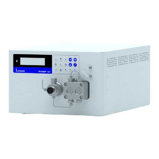
Product information 3. Product information Views 3.1.1 Front view Legend Display Pressure sensor Ventilation screw Keypad Tube connections for the piston backflushing Pump head Fig. 1: Front view 3.1.2 Rear view Legend Warranty seal Space for rear label (with serial number) Fan opening Warning 1 Power switch... -
Page 15: Features
Product information Features Dual-piston technology combined with optimized electronic pulsation ƒ dampen ing and compressibility compensation Liquid transport with low pulsation, stable flow rate and high flow ƒ accuracy Pump head made of stainless steel or with ceramic inlays ƒ Automatic piston backflushing ƒ... -
Page 16: Symbols And Signs
A warranty seal is affixed to some devices. For more information see chap. 1.4.4 on p. 2. Scope of delivery Note: Only use original parts and accessories made by KNAUER or a company authorized by KNAUER. Power cable ƒ BlueShadow Pump 40P with pump head ƒ... -
Page 17: Installation And Initial Startup
Installation and initial startup 4. Installation and initial startup Before you determine the operation site, read the chapter “Technical data” (see chapter 11 on page 58). There you will find all device-speci- fic information on power supply, ambient conditions and humidity. Note: The intended use be ensured only if the requirements for ambient conditions of the operating environment are met. -
Page 18: Space Requirements
Country-specific plugs: Before switching on the device, check whether ƒ the supplied plug is approved for your country. Overview of the de- vice- and country-specific plug types from KNAUER: www.knauer.net/plugs. Power strips: If several devices are connected to one power strip, al- ƒ... -
Page 19: Electric Connections
Installation and initial startup Electric connections Use the Events and Remote pin header to connect the pump with ex- ƒ ternal devices. Use the LAN connection to connect the pump with external devices ƒ within a net work. Alternatively, connect the pump to a computer with the RS-232 port. ƒ... -
Page 20: Remote Connector
Installation and initial startup Process 1. Push the depressor tool into an upper small opening on the front of the terminal strip 2. Lead the cable into the opening below the inserted operating tool. 3. Remove the depressor tool. Next steps Check if the cables are firmly connected. -
Page 21: Events Connector
Installation and initial startup Signal Explanations ANALOG: Analog output signal reflecting either the measu- ƒ red system pressure or a control voltage for Pump The output range can be set to values of max. 1, 2, ƒ 5 and 10 V. ANALOG: IN Analog input signal for controlling the flow rate, e.g.: 1 V for 1 ml/min in the case of the 10 ml pump ƒ... -
Page 22: Connecting The Solvent Bottles
Installation and initial startup 4.5.1 Connecting the solvent bottles To connect the solvent bottles, tubing with pre-installed solvent filters is used. The tubing is connected to the device with flangeless fittings. Note: Do not use any tools to tighten the fittings. Procedure Process Figure... - Page 23 Installation and initial startup Procedure Process Figure 1. Slide the flangeless fitting over the tubing. 2. Insert the tubing into the free inlet on the bottom of the pump head. 3. Tighten the fitting by hand. Fig. 8: Solvent line on pump head Next step Integrate the pump into the HPLC system.
-
Page 24: Control
Fig. 9: Connectors on rear side Note: HPLC devices from KNAUER only work with IP addresses, which have been assigned by IPv4. IPv6 is not supported. This chapter describes how to set up a chromatography system in a local area network (LAN) and how a network administrator can integrate this LAN into your company network. -
Page 25: Configuring Lan Settings
Installation and initial startup Process Procedure 1. On the computer, go to the control panel and check the LAN properties. 2. Hook up the router to the devices and the computer. 3. Set up the router for the computer network. 4. -
Page 26: Configuring The Router
Set the router properties (see chapter 4.6.4 on page 20). 4.6.4 Configuring the router The router is preset at the factory. Information about address, user name and password is noted in the router manual: www.knauer.net/router. Process Procedure 1. To open the router configuration, start your Internet browser and enter the IP address (does not apply for all routers). -
Page 27: Integrating Lan Into The Company Network
Installation and initial startup 4.6.5 Integrating LAN into the company network A network administrator can integrate the LAN into your company net- work. In this case you use the WAN port of the router. Prerequisites There is a patch cable for the connection. ƒ... -
Page 28: Firmware Wizard: Setting A Static Ip Address
Installation and initial startup 4.7.1 Firmware Wizard: Setting a static IP address Note: More information about LAN settings can be found in the Mobile Control Software Instructions in the chapter "Firmware Wizard” (docu- ment no. V6851-2). Text box for serial number of the device Setting IP address... - Page 29 Installation and initial startup Process Procedure 1. In Firmware Wizard, cleck <Reset LAN Settings...>. 2. The window <Device connection settings> opens. Enter serial number of the device into the text field <Target device serial num- ber> 3. Select option <Obtain an IP address automatically> 4.
-
Page 30: Operation
If the device is part of an HPLC system, you should also note the following: The network connection to the router is established ƒ The chromatography software has been installed by KNAUER or a ƒ com pany authorized by KNAUER. The capillaries have been connected. -
Page 31: Isocratic Operating Mode
Operation 5.1.2 Isocratic operating mode Analysis without gradients ƒ The solvent composition is constant during the analysis. ƒ The solvent can be recycled. ƒ 5.1.3 Optimizing HPLC separations To make your HPLC separations as efficient as possible, pay close atten- tion to the following: Task Explanation... -
Page 32: Piston Backflushing
Operation The pump has been switched on and is in „flow mode“. ƒ Tool Syringe with Luer lock ƒ Use the purging solvent to be used in the following application. Note: The purging process may take a while during initial operation be- cause the solvent tubes are filled with liquid for the first time. -
Page 33: Switch On And Self Test
Operation Solvent in the pump Piston backflushing Reverse phase solvents 50% isopropanol or ethanol with 50 % Water (v/v). Normal phase solvents 100 % isopropanol Buffers with high salt Rinse with water containing concentrations 5% ethanol or isopropanol Legend Outlet from the pump head to the solvent bottle Inlet from the solvent... -
Page 34: Led Status
Operation Legend Status LED Status Play/Stop Remote control Gradient modus Parameters/Values RFID recognition of the pump head Keypad Fig. 14: LC display and keypad 5.4.1 LED status The status of the device is indicated by an LED on the front side. The co- lor of the LED shows the current status. -
Page 35: Operating With The Keypad
Operation 5.4.3 Operating with the keypad The keypad consists of 15 buttons, which allow to operate the device. Function Explanation Numeric pad Activation of numeric ƒ pad by pressing the confirmation button at input fields. Changing values. ƒ Navigation button Navigation through ƒ... -
Page 36: Menu Structure
Operation Menu structure 5.5.1 Main menu The main menu contains the current parameters of the pump. Process Figure 1. To navigate between the different main menus, use the horizontal arrow keys 2. In the four main screens the status of the pump is shown. -
Page 37: Menu Structure: Overview
Operation 5.5.2 Menu structure: overview Fig. 15: Menu structure overview BlueShadow Pump 40P Instructions V7613... -
Page 38: Device Setting Parameters
Operation 5.5.3 Device setting parameters Menu Explanation Figure Cntl. Interface Setting for external communi- cation connection of the pump. The connections are on the rear side of the device. RS232-11520, RS232-38400, ƒ RS232-19200, RS232-9600 serial interface LAN-DHCP: Automatic net- ƒ work configuration LAN manual: Manual net- ƒ... - Page 39 Operation Solvent factor Data entry for the compressibili- ty of the selected solvent: Water: 0.46 ƒ Benzene: 0.95 ƒ Chloroform: 0.97 ƒ Ethanol: 1.10 ƒ Acetone: 1.23 ƒ Methanol: 1.21 ƒ n-heptane: 1.40 ƒ n-hexane: 1.50 ƒ Diethyl ether: 1.84 ƒ...
- Page 40 Operation Analog output Output of analog pump signals setup to external devices by means of the remote terminal strip: Offset data entry for the ana- ƒ log output. Full Scale Voltage range opti- ƒ ons: 1 V, 2 V, 5 V Signal source ƒ...
-
Page 41: Glp Menu
Operation — Flow rate value can be changed. This creates a second calibration point which modifies the scaling. Time constant: Set the time ƒ constant for the analog input to be used for signal smoot- hing (0.1-10.0 S). The greater the value of the selected time constant, the stronger the applied signal smoothing. -
Page 42: Create Program
Operation 5.7.1 Create program The use of the display is demonstrated using the example of a program to be created: Program 01 is used to create a solvent gradient (channels A and B) with constant flow of 1 ml/min. The percentage of solvent A is to be continu- ously decreased from 100% to 0 % within 0.50 minutes. -
Page 43: Change Program
Operation 5.7.3 Change program When new values for the different program lines are entered, the old values are overwritten. Procedure 1. Select the menu Program . 2. Select a program number. 3. Navigate to the desired line and value. 4. Activate the numeric pad by pressing and enter a new value. -
Page 44: Link Menu
Operation Link menu The Link menu displays the status of active links. A maximum of ten pro- gram links between defined programs can be created and saved. Navigate Link menu Procedure 1. Open the desired link number. 2. Use the horizontal arrow keys to navigate through the two lines of the display. -
Page 45: Run Link
Operation 5.8.2 Run link After the link has been completed, the display switches to the end mode. Procedure 1. Go to the main menu. 2. Navigate to Link/Program in the lower left display line and choose Link with the vertical arrow key 3. -
Page 46: Functionality Tests
Installation Qualification (IQ) The customer may request the Installation Qualification, which is free of charge. In case of a request, the technical support of KNAUER or from a provider authorized by KNAUER performs this functionality test during the installation. -
Page 47: Troubleshooting
Troubleshooting 7. Troubleshooting First measures: Check all cables and fittings. ƒ Check if air has gotten into the supply lines. ƒ Check the device for leakages. ƒ Further measures: Compare occurring errors with the list of possible errors (see below). ƒ... -
Page 48: Possible Problems And Solutions
Troubleshooting Possible problems and solutions Issue Solution Device cannot be Inspect the power cable to ensure that it is plug- switched on ged into the power supply. When purging, the Check if the venting screw on the pressure sen- pump switches off. sor is opened. -
Page 49: System Messages
Troubleshooting System messages If other system messages are displayed on the display besides those listed below, please turn the device off and then on. Inform the technical support in case the system message repeats. The system messages are in alphabetical order: System message Auto pump head Switch the device off and on... - Page 50 Troubleshooting System message Error input Device error, change device settings. activated GUI communication Switch the device off and on. Inform the techni- failed (internal)! cal support in case the system message repeats itself. Insufficient access Change the entry. Invalid command Change the entry ƒ...
- Page 51 Troubleshooting System message Not enough space Check the pump ƒ to store pro gram Check the number of program lines – a maxi- ƒ mum of 100 program lines are possible Not supported Change the entry. Prg not compatible Modify the program or replace the pump head. with pump head! Program does not Create and edit a program.
-
Page 52: Maintenance And Care
Customer Support. Maintenance contract The following maintenance work on the device may only be performed by KNAUER or a company authorized by KNAUER and is covered by a sepa rate maintenance contract: Opening the device or removing housing parts ƒ... -
Page 53: Flushing The Pump
Maintenance and care Material & size Pump head inlet Pump head outlet Stainless steel 10 ml, 7.5 Nm 7.5 Nm 50 ml Inline filter fittings Torque Stainless steel fittings 7.5 Nm PEEK fittings 3.5 Nm Capillary screw fittings Torque Stainless-steel fittings 5 Nm PEEK fittings 1 Nm Flushing the pump Generally, the pump and all its components should be flushed after each operation. -
Page 54: Maintaining The Pump Head
Maintenance and care Maintaining the pump head 8.5.1 Dismounting the pump head Prerequisites The pump head has been purged. ƒ The tubes at the inlet and outlet have been removed. ƒ The pump head‘s inlet and outlet have been sealed with cap fittings. ƒ... - Page 55 Maintenance and care Procedure Process Figure 1. Loosen the finger-tight fitting . Remove the tubing 2. Fixate the outlet fitting with an open-end wrench (size 13). 3. Loosen the fitting with an open-end wrench (size 1/4“). Remove the capillary. Fig. 17: Outlet screw fitting 4.
-
Page 56: Check Valves
Maintenance and care 8.5.2 Check valves Clogged check valves do not open and close properly. They cause pres- sure fluctuations and irregular flow. If it is impossible to clean the check valves, replace the whole unit. Procedure Removing the check valves ƒ... - Page 57 Maintenance and care 8.5.2.3 Installing the check valve Component defect Damage to components due to excessive tightening possible. Observe the torque of the screw connection Use 5 Nm torque for stainless steel fi ttings. Use 1 Nm torque for PEEK fi ttings. Insert the check valves in the direction of the flow.
-
Page 58: Maintaining The Filter Cartridge At Pressure Sensor
Maintenance and care Maintaining the filter cartridge at pressure sensor Clogged inline filters inside of the pressure sensor can cause pressure fluctuations and irregular flow. Inline filters are not cleaned but exchan- ged as an assembly. Note: It is recommended to replace the filter cartridge after 5 000 working hours. -
Page 59: Inserting A New Filter Cartridge
Maintenance and care Procedure Process Figure 4. Loosen the screw connection of the filter cartridge with the open-end wrench (SW 13) and unscrew it by hand. Fig. 24: Loosen screw connection 5. Remove the polluted fil- ter cartridge with the tweezers. - Page 60 Maintenance and care Procedure Process Figure 1. Insert the filter cart search into the pressure sensor with the marking facing down (A96601) or with the titanium filter disk facing up (A9661). Use the tweezers for this. Fig. 28: Inserting the filter cartridge A96601 2.
-
Page 61: Transport And Storage
Transporting the device Carefully prepare the device for transport or storage. If you want to return your device to KNAUER for repairs, enclose the Service Request Form which can be downloaded from our website. -
Page 62: Storing The Pump Head
Transport and storage algae formation, do not use pure water. Close all inlets and outlets with blind screwings. Prerequisites The pump has been flushed. ƒ The pump has been switched off and disconnected from the power ƒ supply. Tool Open-end wrench, size 10 ƒ... -
Page 63: Disposal
160214. 10.2 WEEE registration number KNAUER as a company is registered by the WEEE number DE 34642789 in the German "Elektroaltgeräteregister" (EAR). The number classifies to category 8 and 9, which, among others, comprises laboratory equipment. -
Page 64: Technical Data
Technical data 11. Technical data 11.1 Solvent delivery Pump type Analytical high pressure pump Delivery system Dual piston pump with one working pis- ton, one auxiliary Pulsation compensation Active pulsation compensation Flow properties 10 ml pump head: 0.001–10 ml/min ƒ 50 ml pump head: 0.01–50 ml/min ƒ... -
Page 65: Communication
Technical data 11.2 Communication Analog inputs Flow (0–10 V) Analog control input Flow rate Control ƒ RS-232 ƒ Remote control connections (Stop, Flow, ƒ Pressure, Error) Keypad ƒ Programming 19 programs, 10 program links, 1 WAKE UP pro gram (program 20) 11.3 Technical parameters Special features The system pump head is detected automatically using radio frequency... -
Page 66: Chemical Compatibility Of Wetted Materials
The following list contains information about the chemical compatibility of all wetted materials which are used in devices made by KNAUER. The data bases on a literature research on the manufacturer specifications of the materials. The wetted materials of this device are listed in the chapter “Technical data”. - Page 67 Chemical compatibility of wetted materials Polyimide (Vespel®) This material is wear-resistant and permanent resilient thermically (up to 200 °C) as well as mechanically. It is chemically broadly inert (pH range 1-10) and is especially resistant against acidic to neutral and organic solvents, but vulnerable to pH strong chemical or oxidizing environments: It is incompatible with concentrated mineral acids (such as sulfuric acid), glacial acetic acid, DMSO and THF.
-
Page 68: Non-Metals
Chemical compatibility of wetted materials Polychlortrifluorethylene (PCTFE, Kel-F®) The semi-crystalline thermoplastic material is plasticizer-free and dimen- sionally stable, even in a wide temperature range (−240 °C to+205 °C). It is moderately resistent against ether, halogenated solvents and toluene. Halogenated solvents over +60 °C and chlorine gas should not be used. Fluorinated rubber (FKM) The elastomer consisting of fluorinated hydrocarbon stands out due to a high resistance against mineral oils, synthetic hydraulic fluids, fuels,... -
Page 69: Metals
Chemical compatibility of wetted materials Mineral wool This insulating material consists of glass or stone wool fibres and isolates in high oxidizing conditions and at high temperatures. Mineral wool is valid as commonly inert against organic solvents and acids. Glass, glass fibre, quartz, quartz glass These mineral materials are resistant against corrosion and wear and are mostly chemical inert. -
Page 70: Repeat Orders
13. Repeat orders 13.1 Devices Article Order no. Basic device with stainless steel pressure sensor, APC40 without pump head, with accessories Basic device with metal-free pressure sensor, APC60 without pump head, with accessories Pump with 10 ml-Pump head, stainless steel, APC40EA with accessories Pump with 10 ml-Pump head, ceramic, APC60EB... - Page 71 Repeat orders Article Order no. 50 ml pump head, stainless steel, accessories AHC20 50 ml pump head, stainless steel, for normal AHC20BA phase applications, accessories 50 ml pump head, stainless steel, for water AHC20FA applications 50 ml pump head, stainless steel for high tempe- AHC20CA rature applications 50 ml pump head, stainless steel, for high tempe-...
- Page 72 Latest KNAUER instructions online: www.knauer.net/library KNAUER Phone: +49 30 809727-0 Wissenschaftliche Geräte GmbH Fax: +49 30 8015010 Hegauer Weg 38 E-Mail: info@knauer.net 14163 Berlin Internet: www.knauer.net © KNAUER 2020...
Need help?
Do you have a question about the BlueShadow 40P and is the answer not in the manual?
Questions and answers