
Subscribe to Our Youtube Channel
Related Manuals for Sentera Controls SPS2


Summary of Contents for Sentera Controls SPS2
- Page 1 SPS2 DIFFERENTIAL PRESSURE CONTROLLER WITH TWO SETPOINTS Mounting and operating instructions...
-
Page 2: Table Of Contents
OPERATIONAL DIAGRAM WIRING AND CONNECTIONS MOUNTING INSTRUCTIONS IN STEPS OPERATING INSTRUCTIONS VERIFICATION OF THE INSTALLATION INSTRUCTIONS TRANSPORT AND STORAGE WARRANTY AND RESTRICTIONS MAINTENANCE MIW-SPS2-EN-000 - 25 / 04 / 2024 2 - 130 www.sentera.eu back to the table of contents... -
Page 3: Safety And Precautions
If you have any further questions, please contact your technical support or consult a professional. MIW-SPS2-EN-000 - 25 / 04 / 2024 3 - 130 www.sentera.eu back to the table of contents... -
Page 4: Product Description
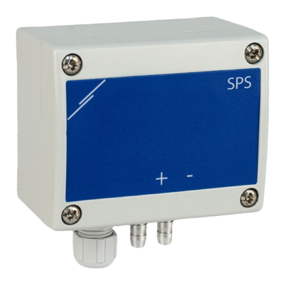
TWO SETPOINTS PRODUCT DESCRIPTION The SPS2 differential pressure controller directly controls EC fans, frequency inverters or other control units with two differential pressure setpoints (high/low or day/night mode option). It provides an analogue or digital output with integrated PI control and K-factor setting. -
Page 5: Operational Diagram
Never connect a device powered by a DC voltage to the common ground of a product of the -G type. This could harm the connected devices permanently. MIW-SPS2-EN-000 - 25 / 04 / 2024 5 - 130 www.sentera.eu... -
Page 6: Mounting Instructions In Steps
To control differential pressure, use PSET-QF or PSET-PVC set (pressure measurement is the unit default setting); To control volume flow, use PSET-PT Pitot tube connection set, PSET-QF or PSET-PVC connection set. MIW-SPS2-EN-000 - 25 / 04 / 2024 6 - 130 www.sentera.eu back to the table of contents... - Page 7 PWM GND (5—50Vdc) Optional settings To assure correct communication, the NBT needs to be activated in only two devices on the Modbus RTU network. MIW-SPS2-EN-000 - 25 / 04 / 2024 7 - 130 www.sentera.eu back to the table of contents...
-
Page 8: Operating Instructions
Press button SW2 for 4 seconds until blue LED on the printed circuit board blinks two times and keep pressing this button until the blue LED is blinks three times. The Modbus registers are reset to their default values (factory pre-set). MIW-SPS2-EN-000 - 25 / 04 / 2024 8 - 130 www.sentera.eu... -
Page 9: Verification Of The Installation Instructions
For more information, click here to refer to the product datasheet - Settings. Fig. 9 LED indications Power on / Normal operation Modbus communication MIW-SPS2-EN-000 - 25 / 04 / 2024 9 - 130 www.sentera.eu back to the table of contents... -
Page 10: Transport And Storage
SMD LED for indication of activity on the transmit line B l i n k i n g TRANSPORT AND STORAGE Avoid shocks and extreme conditions; stock in original packing. MIW-SPS2-EN-000 - 25 / 04 / 2024 10 - 130 www.sentera.eu back to the table of contents... -
Page 11: Warranty And Restrictions
In case of heavy pollution, clean with a non-aggressive product. In these circumstances the unit should be disconnected from the supply. Pay attention that no fluids enter the unit. Only reconnect it to the supply when it is completely dry. MIW-SPS2-EN-000 - 25 / 04 / 2024 11 - 130 www.sentera.eu... - Page 12 SPS2 DIFFERENTIAL PRESSURE CONTROLLER WITH TWO SETPOINTS MIW-SPS2-EN-000 - 25 / 04 / 2024 12 - 130 www.sentera.eu back to the table of contents...
- Page 13 SPS2 DIFFERENTIAL PRESSURE CONTROLLER WITH TWO SETPOINTS MIW-SPS2-EN-000 - 25 / 04 / 2024 13 - 130 www.sentera.eu back to the table of contents...
Need help?
Do you have a question about the SPS2 and is the answer not in the manual?
Questions and answers