Table of Contents
Advertisement
Quick Links
Advertisement
Table of Contents

Subscribe to Our Youtube Channel
Related Manuals for Sentera Controls MTP-D010 Series


Summary of Contents for Sentera Controls MTP-D010 Series
- Page 1 MTP-D010 ACTIVE POTENTIOMETER Mounting and operating instructions...
- Page 2 MTP-D010 ACTIVE POTENTIOMETER Table of contents SAFETY AND PRECAUTIONS PRODUCT DESCRIPTION ARTICLE CODES INTENDED AREA OF USE TECHNICAL DATA STANDARDS OPERATIONAL DIAGRAMS WIRING AND CONNECTIONS MOUNTING INSTRUCTIONS IN STEPS VERIFICATION OF INSTALLATION INSTRUCTIONS TRANSPORT AND STORAGE WARRANTY AND RESTRICTIONS MAINTENANCE MIW-MTP-D010-AT-BT-EN-000 - 06 / 02 / 2019 2 - 7 www.sentera.eu...
- Page 3 MTP-D010 ACTIVE POTENTIOMETER SAFETY AND PRECAUTIONS Read all the information, the datasheet, mounting and operating instructions and study the wiring and connection diagram before working with the product. For personal and equipment safety, and for optimum product performance, make sure you entirely understand the contents before installing, using, or maintaining this product.
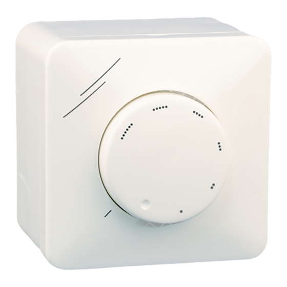
- Page 4 MTP-D010 ACTIVE POTENTIOMETER PRODUCT DESCRIPTION MTP-D010 potentiometer series are intended for direct control of EC fans / motors and actuators. They require a supply voltage of 3—15 VDC and provide a stepless output signal that can be set by a rotary knob within a range adjustable via two trimmers for Vmin (10—70 % Vin) and Vmax (30—100% Vin).
- Page 5 MTP-D010 ACTIVE POTENTIOMETER OPERATIONAL DIAGRAMS MTP-D010-AT MTP-D010-BT Output, VDC Output, VDC 100 % Vin 100 % Vin Vmax Vmax 70 % Vin 70 % Vin Vmin Vmin 30 % Vin 30 % Vin 10 % Vin 10 % Vin Min. Potentiometer position Potentiometer position WIRING AND CONNECTIONS...
- Page 6 MTP-D010 ACTIVE POTENTIOMETER Fig. 2 Mounting dimensions - inset mounting NO T E Mount the unit so that the terminal block and connections are at the lower side. Adjust the Vmin and Vmax trimmers. Mount back the cover and secure it with the nut. Put back the knob and turn it to off position (-AT version) or minimum position (-BT version).
- Page 7 MTP-D010 ACTIVE POTENTIOMETER A 5 mm hole can be drilled at the bottom of the external enclosure to drain the NO T E condensed water. VERIFICATION OF INSTALLATION INSTRUCTIONS ATTENTION Use only tools and equipment with non-conducting handles when working on electrical devices.
Need help?
Do you have a question about the MTP-D010 Series and is the answer not in the manual?
Questions and answers