Table of Contents
Advertisement
Quick Links
Advertisement
Table of Contents

Subscribe to Our Youtube Channel
Related Manuals for Sentera Controls GTEX1-60-DM


Summary of Contents for Sentera Controls GTEX1-60-DM
- Page 1 GTEX1-60 ELECTRONIC FAN SPEED CONTROLLER Mounting and operating instructions...
-
Page 2: Table Of Contents
GTEX1-60 ELECTRONIC FAN SPEED CONTROLLER Table of contents SAFETY AND PRECAUTIONS PRODUCT DESCRIPTION ARTICLE CODES INTENDED AREA OF USE TECHNICAL DATA STANDARDS WIRING AND CONNECTIONS OPERATIONAL DIAGRAM MOUNTING INSTRUCTIONS IN STEPS VERIFICATION OF INSTALLATION INSTRUCTIONS MODBUS REGISTERS MAPS TRANSPORT AND STOCK KEEPING INFORMATION WARRANTY INFORMATION AND RESTRICTIONS MAINTENANCE MIW-GTE-EN-000 - 17 / 01 / 2018... -
Page 3: Safety And Precautions
GTEX1-60 ELECTRONIC FAN SPEED CONTROLLER SAFETY AND PRECAUTIONS Read all the information, the datasheet, mounting and operating instructions and study the wiring and connection diagram before working with the product. For personal and equipment safety, and for optimum product performance, make sure you entirely understand the contents before installing, using, or maintaining this product. -
Page 4: Product Description
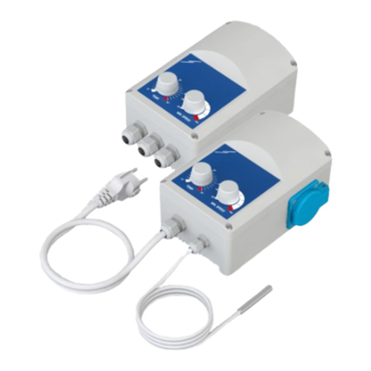
GTEX1-60 ELECTRONIC FAN SPEED CONTROLLER PRODUCT DESCRIPTION The GTE fan speed controller automatically regulates the speed of single phase voltage controllable motors (230 VAC / 50—60 Hz) according to the measured temperature values. The maximum speed can be adjusted via an internal trimmer. -
Page 5: Standards
AC:2005 and EN 61000-6-3:2007/A1:2011/AC:2012 ■ WEEE Directive 2012/19/EC ■ RoHs Directive 2011/65/EC WIRING AND CONNECTIONS GTEX1-60-DM Supply voltage 230 VAC / 50—60 Hz – mono phase ± 10% Neutral 230 VAC not regulated output (max. 2 A) PT500 temperature sensor GND, T (TEMP.) -
Page 6: Mounting Instructions In Steps
GTEX1-60 ELECTRONIC FAN SPEED CONTROLLER MOUNTING INSTRUCTIONS IN STEPS Before you start mounting the GTE controller, read carefully “Safety and Precautions”. Choose a flat surface for installation (e.g. a wall, panel, etc.) and follow these steps: Insert the supply and sensor cables through the cable glands and do the wiring according to the information in section “Wiring and connections”... - Page 7 GTEX1-60 ELECTRONIC FAN SPEED CONTROLLER ▶ -DM version mounting steps: Go to -DT version Make sure the GTE controller is not connected to the mains supply. Unscrew the front cover and open the enclosure. Mind the wires that connect the potentiometer with the printed circuit board. Fix the unit to the wall or panel using the provided screws and dowels.
- Page 8 GTEX1-60 ELECTRONIC FAN SPEED CONTROLLER ▶ -DT version mounting steps: Back to -DM version Make sure the GTE controller is not connected to the mains supply. Unscrew the front cover and open the enclosure. Mind the wires that connect the potentiometer with the printed circuit board. Fix the unit to the wall or panel using the provided screws and dowels.
-
Page 9: Verification Of Installation Instructions
GTEX1-60 ELECTRONIC FAN SPEED CONTROLLER VERIFICATION OF INSTALLATION INSTRUCTIONS ATTENTION Mind that the cables are live. Take the relevant safety measures. Plug in the supply cable. Switch on the controller via the illuminated ON/OFF switch. Position the TEMP. potentiometer to max. position (35 °C). (See Fig. 9 -DM version and Fig. -
Page 10: Modbus Registers Maps
GTEX1-60 ELECTRONIC FAN SPEED CONTROLLER MODBUS REGISTERS MAPS INPUT REGISTERS (Read-only) Data type Description Data Values 0,0 °C Temperature input unsigned int. Analog temperature input 0—600 600 = 60.0 °C 170 = 170 VAC Vmax unsigned int. Max. motor speed value 170—230 230 = 230 VAC... -
Page 11: Transport And Stock Keeping Information
GTEX1-60 ELECTRONIC FAN SPEED CONTROLLER TRANSPORT AND STOCK KEEPING INFORMATION Avoid shocks and extreme conditions; stock in the original packing. WARRANTY INFORMATION AND RESTRICTIONS Two years from the delivery date against defects in manufacturing. Any modifications or alterations to the product after the date of publication relieve the manufacturer of any responsibilities.
Need help?
Do you have a question about the GTEX1-60-DM and is the answer not in the manual?
Questions and answers