
Subscribe to Our Youtube Channel
Related Manuals for Sentera Controls STVS1 Series


Summary of Contents for Sentera Controls STVS1 Series
- Page 1 STVS1 230 VAC TRANSFORMER CONTROLLER WITH ANALOGUE INPUT Mounting and operating instructions...
-
Page 2: Table Of Contents
STVS1 230 VAC TRANSFORMER CONTROLLER WITH ANALOGUE INPUT Table of contents SAFETY AND PRECAUTIONS PRODUCT DESCRIPTION ARTICLE CODES INTENDED AREA OF USE TECHNICAL DATA STANDARDS OPERATIONAL DIAGRAM WIRING AND CONNECTIONS MOUNTING INSTRUCTIONS IN STEPS VERIFICATION OF INSTALLATION TRANSPORT AND STORAGE WARRANTY AND RESTRICTIONS MAINTENANCE MIW-STVS1-EN-000 - 24 / 03 / 2022... -
Page 3: Safety And Precautions
STVS1 230 VAC TRANSFORMER CONTROLLER WITH ANALOGUE INPUT SAFETY AND PRECAUTIONS Read all the information, the datasheet, Modbus map, mounting and operating instructions and study the wiring and connection diagram before working with the product. For personal and equipment safety, and for optimum product performance, make sure you entirely understand the contents before installing, using, or maintaining this product. -
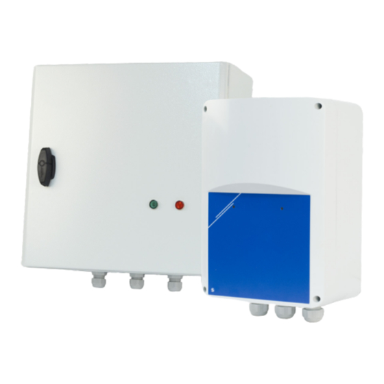
Page 4: Product Description
ANALOGUE INPUT PRODUCT DESCRIPTION The STVS1 series of transformer fan speed controllers regulate the speed of single-phase voltage controllable motors in five steps by varying the output voltage according to an 0—10 VDC analogue input signal. They are equipped with autotransformer(s) and feature TK monitoring for thermal motor protection. -
Page 5: Operational Diagram
STVS1 230 VAC TRANSFORMER CONTROLLER WITH ANALOGUE INPUT OPERATIONAL DIAGRAM L22 series U (VAC)/ Speed Analogue input / Control signal 2; 4; 6; 8; 9,5 VDC Switching levels Down Up level — 0,2 VDC WIRING AND CONNECTIONS Wiring and connections Power supply, phase (230 VAC / 50—60 Hz) Power supply, neutral Earth terminal... - Page 6 STVS1 230 VAC TRANSFORMER CONTROLLER WITH ANALOGUE INPUT MOUNTING INSTRUCTIONS IN STEPS Before you start mounting the STVS1, read carefully “Safety and Precautions” and follow these steps. Choose a smooth solid surface for installation (a wall, panel, etc.). Follow these steps: Unscrew the front cover and open the enclosure.
- Page 7 STVS1 230 VAC TRANSFORMER CONTROLLER WITH ANALOGUE INPUT If applicable, connect the unregulated output (L1 and N). It can be used to supply a 230 VAC valve, lamp, etc. when the knob is not at ‘0’ position (see Table 1 below). Connect the TK contacts for monitoring of the thermal motor protection to the motor TK terminals.
- Page 8 STVS1 230 VAC TRANSFORMER CONTROLLER WITH ANALOGUE INPUT switch). Operate the controller via the external device output voltages. Optional settings The standard configuration of the output voltages is as indicated in Table 1 below. However, because more than 5 output voltages are available, it is possible to adjust the 5 steps by changing the internal wiring.
- Page 9 STVS1 230 VAC TRANSFORMER CONTROLLER WITH ANALOGUE INPUT TRANSPORT AND STORAGE Avoid shocks and extreme conditions; stock in original packing. WARRANTY AND RESTRICTIONS Two years from the delivery date against defects in manufacturing. Any modifications or alterations to the product after the date of publication relieve the manufacturer of any responsibilities.
Need help?
Do you have a question about the STVS1 Series and is the answer not in the manual?
Questions and answers