Table of Contents
Advertisement
Quick Links
Advertisement
Table of Contents

Subscribe to Our Youtube Channel
Related Manuals for Sentera Controls MCS-1-LCD


Summary of Contents for Sentera Controls MCS-1-LCD
- Page 1 MCS-1-LCD MULTIFUNCTIONAL LOGIC CONTROLLER Mounting and operating instructions...
-
Page 2: Table Of Contents
INTENDED AREA OF USE TECHNICAL DATA STANDARDS WIRING AND CONNECTIONS OPERATIONAL DIAGRAMS MOUNTING INSTRUCTIONS IN STEPS VERIFICATION OF THE CORRECT INSTALLATION OPERATING INSTRUCTIONS CONTROLLER OVERVIEW CONTROL FUNCTIONS OVERVIEW PARAMETERS AND DEFAULT SETTINGS MIW-MCS-1-LCD-EN-000 - 20 / 07 / 2016 2 - 33 www.sentera.eu... - Page 3 DEVICE FUNCTIONALITY SELECTION ANALOGUE INPUTS SETUP DIGITAL INPUTS SETUP ANALOGUE OUTPUTS SETUP RELAY CONTACT SETUP SCHEDULE RUN SETTINGS MODBUS REGISTER MAPS TRANSPORT AND STOCK KEEPING INFORMATION WARRANTY INFORMATION AND RESTRICTIONS MAINTENANCE MIW-MCS-1-LCD-EN-000 - 20 / 07 / 2016 3 - 33 www.sentera.eu...
-
Page 4: Safety And Precautions
In case there are any questions that are not answered, please contact your technical support or consult a professional. MIW-MCS-1-LCD-EN-000 - 20 / 07 / 2016 4 - 33 www.sentera.eu back to the table of contents... -
Page 5: Product Description
MULTIFUNCTIONAL LOGIC CONTROLLER PRODUCT DESCRIPTION The MCS-1-LCD multifunctional logic controller has integrated analogue, digital and relay outputs which are free configurable. Its multiple analogue, digital and temperature inputs ensure functionality in a large range of HVAC applications. All functional parameters and settings are accessible either via a 4-button interface with LCD display, via a user-friendly monitoring software application for Windows or via 3SModbus. -
Page 6: Standards
Modbus RTU (RS485) signal /A Cable cross section: max. 1,5 / 2,5 mm Connections Cable gland clamping range: 3—6 mm 2 USB sockets, type Mini B MIW-MCS-1-LCD-EN-000 - 20 / 07 / 2016 6 - 33 www.sentera.eu back to the table of contents... -
Page 7: Operational Diagrams
DIX maximum speed Maximum Maximum Related value Related value Active state Inactive state t, [s] Active state Inactive state t,[s] event event event event MIW-MCS-1-LCD-EN-000 - 20 / 07 / 2016 7 - 33 www.sentera.eu back to the table of contents... -
Page 8: Mounting Instructions In Steps
When you first use the unit make sure that the load corresponds to the default output values. If the default values do not fit the load used, configure the unit first, then connect the load. Improper load may cause damage to the controller. MIW-MCS-1-LCD-EN-000 - 20 / 07 / 2016 8 - 33 www.sentera.eu... - Page 9 Fix the rear lid of the enclosure on the wall / panel by the delivered dowels and screws. Mind the correct mounting position and unit mounting dimensions. (See Fig 5 Mounting dimensions and Fig 6 Mounting position.) MIW-MCS-1-LCD-EN-000 - 20 / 07 / 2016 9 - 33 www.sentera.eu...
-
Page 10: Verification Of The Correct Installation
ATTENTION Be careful when you are handling with the ribbon cable. It must not touch the power supply block. This will damage your unit. See Fig 8. MIW-MCS-1-LCD-EN-000 - 20 / 07 / 2016 10 - 33 www.sentera.eu back to the table of contents... - Page 11 If they blink your unit has detected a Modbus network. If they do not, check the connections again. Fig 9 Modbus communication indication MIW-MCS-1-LCD-EN-000 - 20 / 07 / 2016 11 - 33 www.sentera.eu back to the table of contents...
-
Page 12: Operating Instructions
Control CONTROL FUNCTIONS OVERVIEW The MCS-1-LCD controller features integrated analogue and relay outputs which can be controlled either in one of the pre-configured modes or they can be personalised. Its numerous different analogue, digital and temperature inputs ensure a large range of functional control. - Page 13 In case there is an assigned digital input for relay switching, the relay contact switches open or closed at the event of active state and switches back (closed or open) when the state changes to inactive. MIW-MCS-1-LCD-EN-000 - 20 / 07 / 2016 13 - 33 www.sentera.eu...
-
Page 14: Parameters And Default Settings
Relay contacts 1 and 2 (Rc1 & Rc2) Assigned input(s) Not in use Functionality Device functionality Temperature Cool Passwords Installer password 0000 User password 0000 MIW-MCS-1-LCD-EN-000 - 20 / 07 / 2016 14 - 33 www.sentera.eu back to the table of contents... -
Page 15: Configuring The Parameters
Fig 10 Mode selector MODE BOOT NO T E The USB interface allows LCD display and control board firmware updates. To update contact the technical support. MIW-MCS-1-LCD-EN-000 - 20 / 07 / 2016 15 - 33 www.sentera.eu back to the table of contents... -
Page 16: Using Predefined Templates
Linear Linear Controlled function (Ao2) Analog output Cool Heat 0—10 VDC Cool mode (Ao2) Assigned normal input (Ao2) Assigned high priority input (Ao2) MIW-MCS-1-LCD-EN-000 - 20 / 07 / 2016 16 - 33 www.sentera.eu back to the table of contents... -
Page 17: Customising The Settings
Fig 11 USB connector J1 ATTENTION The USB connector J4 shown in Fig 12 is for firmware updates only. Fig 12 USB connector J4 MIW-MCS-1-LCD-EN-000 - 20 / 07 / 2016 17 - 33 www.sentera.eu back to the table of contents... -
Page 18: 3Smodbus Software
For further information about parameter configuring refer to the chapter “Main menu structure”. 3SMODBUS SOFTWARE 3SModbus is a free application for Windows. You can download it from our website http://www.senteracontrols.com/3smodbus/3smodbus.exe MIW-MCS-1-LCD-EN-000 - 20 / 07 / 2016 18 - 33 www.sentera.eu back to the table of contents... -
Page 19: 4-Buton Keyboard Interface
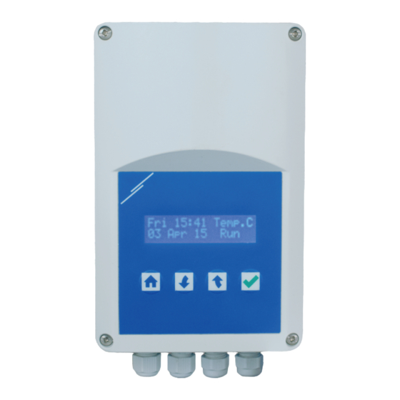
4-BUTON KEYBOARD INTERFACE Fig 17 LCD display home screen To configure the MCS-1-LCD, use the 4-button interface and LCD display following the menu structure. (See chapter “Main menu structure”.). For the parameter default values, please refer to “Modbus register maps” chapter. -
Page 20: Main Menu Structure
Remove installer Bootloader password Reset installer Reset to default password Change user User or installer password password prompt Remove user password Reset user password MIW-MCS-1-LCD-EN-000 - 20 / 07 / 2016 20 - 33 www.sentera.eu back to the table of contents... -
Page 21: Device Functionality Selection
MULTIFUNCTIONAL LOGIC CONTROLLER DEVICE FUNCTIONALITY SELECTION Temperature cool Temperature heat Relative humidity Air quality Differential pressure Temperature and CO Differential pressure and temperature Free MIW-MCS-1-LCD-EN-000 - 20 / 07 / 2016 21 - 33 www.sentera.eu back to the table of contents... -
Page 22: Analogue Inputs Setup
2—10 VDC Set range reference 4—20 mA Set range reference Free Enter units Celsius Units Temp Set range reference Fahrenheit Set range reference MIW-MCS-1-LCD-EN-000 - 20 / 07 / 2016 22 - 33 www.sentera.eu back to the table of contents... -
Page 23: Digital Inputs Setup
Mode selection Ao1 Remote off Ao2 Remote off Ao2 Maximum output Ao2 Maximum output Ao2 Mode selection Ao2 Mode selection Ao2 Relay control Relay control MIW-MCS-1-LCD-EN-000 - 20 / 07 / 2016 23 - 33 www.sentera.eu back to the table of contents... -
Page 24: Analogue Outputs Setup
If PID function Ti value is selected Cool Controlled If PID function Td value is selected Heat If PID function Autotune is selected Cool MIW-MCS-1-LCD-EN-000 - 20 / 07 / 2016 24 - 33 www.sentera.eu back to the table of contents... -
Page 25: Relay Contact Setup
Not in use Assign input Assign input Not in use Only active or related inputs are listed Only active or related inputs are listed MIW-MCS-1-LCD-EN-000 - 20 / 07 / 2016 25 - 33 www.sentera.eu back to the table of contents... -
Page 26: Schedule
Run periods Standby periods Period 1 Period 1 Period 2 Period 2 Period 3 Period 3 Period 4 Period 4 MIW-MCS-1-LCD-EN-000 - 20 / 07 / 2016 26 - 33 www.sentera.eu back to the table of contents... -
Page 27: Run Settings
PID Off level Hysteresis controlled analogue output If assigned in linear If assigned in or primary controlled secondary controlled analogue output analogue output MIW-MCS-1-LCD-EN-000 - 20 / 07 / 2016 27 - 33 www.sentera.eu back to the table of contents... -
Page 28: Modbus Register Maps
Selected analogue input control range (Ai1), Analogue input control range (Ai1) unsigned int. 0—1.000 0—1.000 0—10 VDC calculated from holding registers values MIW-MCS-1-LCD-EN-000 - 20 / 07 / 2016 28 - 33 www.sentera.eu back to the table of contents... - Page 29 Setpoint for temperature signed int. only if assigned to a controlled analogue -200—600 200 = 20 °C input (T2) output, PID or relay output. MIW-MCS-1-LCD-EN-000 - 20 / 07 / 2016 29 - 33 www.sentera.eu back to the table of contents...
- Page 30 Maximum output for Ao2 Mode selection Ao2 Relay control Digital input active state High unsigned int. Selects active state for digital input Di4 0—1 (Di4) MIW-MCS-1-LCD-EN-000 - 20 / 07 / 2016 30 - 33 www.sentera.eu back to the table of contents...
- Page 31 Assigns normal analogue or temperature Assign normal input to unsigned int. input to analogue output Ao2. Active 0—3 analogue output (Ao2) only if not in relation. MIW-MCS-1-LCD-EN-000 - 20 / 07 / 2016 31 - 33 www.sentera.eu back to the table of contents...
- Page 32 8 are set to 1. 93-100 Reserved, returns 0 If you want to find out more about Modbus over serial line, please visit: http://www.modbus.org/docs/Modbus_over_serial_line_V1_02.pdf MIW-MCS-1-LCD-EN-000 - 20 / 07 / 2016 32 - 33 www.sentera.eu back to the table of contents...
-
Page 33: Transport And Stock Keeping Information
In case of heavy pollution, clean with a non-aggressive product. In these circumstances the unit should be disconnected from the supply. Pay attention that no fluids enter the unit. Only reconnect it to the supply when it is completely dry. MIW-MCS-1-LCD-EN-000 - 20 / 07 / 2016 33 - 33 www.sentera.eu...
Need help?
Do you have a question about the MCS-1-LCD and is the answer not in the manual?
Questions and answers