Table of Contents
Advertisement
Quick Links
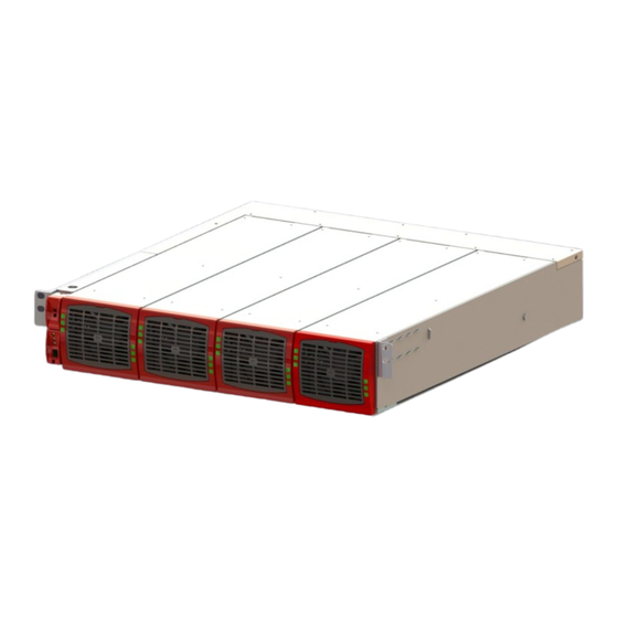
TSI BRAVO - 125 VDC
User Manual V7.0
BEYOND THE INVERTER
THE NEW GENERATION OF POWER CONVERTERS
DUAL INPUT INVERTER
The Commercial Power as default source
AC BACKUP IN A DC ENVIRONMENT
Leverage your existing DC infrastructure
ONE STOP SHOP
wide output power range
HARSHEST AC INPUT CONDITIONS
Without compromising the quality of the AC output
Copyright © 2013. Construction electroniques & telecommunications S.A.
All rights reserved. The contents in document are subject to change without notice.
The products presented are protected by several international patents and trademarks.
Address: CE+T S.a, Rue du Charbonnage 12, B 4020 Wandre, Belgium
www.cet-power.com - info@cet-power.com
www.cet-power.com
Advertisement
Table of Contents
Troubleshooting

Related Manuals for CE+T Power TSI BRAVO 125 VDC


Summary of Contents for CE+T Power TSI BRAVO 125 VDC
- Page 1 TSI BRAVO - 125 VDC User Manual V7.0 BEYOND THE INVERTER THE NEW GENERATION OF POWER CONVERTERS DUAL INPUT INVERTER The Commercial Power as default source AC BACKUP IN A DC ENVIRONMENT Leverage your existing DC infrastructure ONE STOP SHOP wide output power range HARSHEST AC INPUT CONDITIONS Without compromising the quality of the AC output...
-
Page 2: Table Of Contents
7.3 Electrical installation (Bravo PACK or single shelf) ..................... 7.3.1 Pre requisites............................7.3.2 Terminations ............................7.3.3 Grounding ............................. 7.3.4 DC Input ............................... 7.3.5 AC Input ..............................7.3.6 AC output.............................. 7.3.7 Signalling.............................. 7.3.8 Rear cover ............................8. Human-Machine Interface ............................– TSI Bravo 125 VDC– User manual – v7.0... - Page 3 13.2 Defective modules ............................13.2.1 Replacing modules ..........................13.2.2 Return defective T2S interface ......................13.2.3 Return defective shelf .......................... 13.2.4 Return defective modules ........................14. Service ..................................15. Maintenance Task ..............................– TSI Bravo 125 VDC– User manual – v7.0...
- Page 4 Release Note: Release date Modified page Version Modifications (DD/MM/YYYY) number 12/08/2014 Release of the Manual. – TSI Bravo 125 VDC– User manual – v7.0...
-
Page 5: Ce+T At A Glance
CE+T at a glance 1. CE+T at a glance CE+T Power designs, manufactures and markets a range of products for industrial operators with mission critical applications, who are not satisfied with existing AC backup systems performances, and related maintenance costs. -
Page 6: Abbreviations
Direct current Electro Static Discharge Main Earth Terminal Manual By-pass TCP/IP Transmission Control Protocol/Internet Protocol Universal Serial Bus Protective Earth (also called Main Protective Conductor) Neutral Printed Circuit Board True Redundant Structure – TSI Bravo 125 VDC– User manual – v7.0... -
Page 7: Safety Instructions
(see 7.5.3, page 20). Ground the enclosure to the electrode terminal(see 7.5.2, page 20) in accordance with local code requirements. „ „ AC and DC circuits shall be terminated with no voltage / power applied. – TSI Bravo 125 VDC– User manual – v7.0... -
Page 8: Handling
If the equipment is dismantled, to dispose of the products it consists of, you must stick to the local regulations in force in „ „ the country of destination and in any case avoid causing any kind of pollution. To download the latest documentation and software, please visit our website at www.cet-power.com. – TSI Bravo 125 VDC– User manual – v7.0... -
Page 9: Tsi Technology
1 | Information and data given in this chapter intend to for an overview on the technology. Detailed features and parameters for each individual module type of the range may differ and should be referred in the dedicated data sheet. – TSI Bravo 125 VDC– User manual – v7.0... -
Page 10: Safe Mode
. A specific example of Mix-mode is the Walk-in mode where the transfer from DC source to AC source is ramped up within a fix and adjustable period of time. – TSI Bravo 125 VDC– User manual – v7.0... -
Page 11: Inverter Components
Optional rear cover can be provided for enhanced safety in cabinet. „ „ 18.9” (D) x 19” (W) x 2U (H). [480mm (D) x 19” (W) x 2U (H)]. 13 Lbs [6 Kg] empty. „ „ – TSI Bravo 125 VDC– User manual – v7.0... -
Page 12: Accessories
Indoor sites are considered to have a working lightning surge suppression device in service. „ „ Indoor sites Min Class II. „ „ Outdoor sites Min Class I + Class II or combined Class I+II. – TSI Bravo 125 VDC– User manual – v7.0... -
Page 13: Tsi Bravo Shelves Installation
„ 19” – 600mm depth cabinets (most standard solution, which is supplied by default - shown here). „ „ 19” – 800mm depth cabinets. ETSI – 600mm depth cabinets. „ „ – TSI Bravo 125 VDC– User manual – v7.0... -
Page 14: Mouting Kit
Fix cage nuts in the cabinet front and rear frame of the left and the right side Fix the left and right slider of the cabinet with the supplied mounting screws. – TSI Bravo 125 VDC– User manual – v7.0... -
Page 15: Electrical Installation (Bravo Pack Or Single Shelf)
„ „ DC Input-Individual (per module), observe polarity. „ „ AC Input / AC output –Common (per shelf), respect phases. Wire all positions in the sub-rack for future expansion „ „ – TSI Bravo 125 VDC– User manual – v7.0... -
Page 16: Terminations
20 A 2 x 12 AWG ( 4 mm 7.3.5 AC Input CB per shelf Cable, min Connector Torque 120 VAC 2p 100A 3 x 4 AWG ( 2 x 16 mm – TSI Bravo 125 VDC– User manual – v7.0... -
Page 17: Ac Output
If both transitions are not picked up the status is not changed. Common Digital input characteristics (Remote On/Off) „ „ - Signal voltage +5VDC (galvanically insulated) - Max wire size 17 AWG (1mm2) – TSI Bravo 125 VDC– User manual – v7.0... -
Page 18: Rear Cover
The rear cover is snapped in position in the rear of the sub-rack. „ „ Remove material using a pair of side cutters to allow cables enter and exit. The rear cover is ordered separately. „ „ – TSI Bravo 125 VDC– User manual – v7.0... -
Page 19: Human-Machine Interface
USB port - Non urgent 30 second delay „ „ Parameter setting via Laptop or Copy/Paste. Factory default according to list of set values, see Table of set values „ „ – TSI Bravo 125 VDC– User manual – v7.0... -
Page 20: System Set Up
Bits per second 115200 Data bits „ „ Parity None „ „ Stop bits „ „ „ „ Flow control None Remark: Refer to document XXXX for detailed system setting and operation. – TSI Bravo 125 VDC– User manual – v7.0... -
Page 21: Menu Access
1 > Force refresh of configuration texts and constants 2 > Force refresh of events description texts 4 > Security Access 0 > Return to index 1 > Enable Password protectio – TSI Bravo 125 VDC– User manual – v7.0... -
Page 22: Inserting/Removing/Replacing Modules
Close the cover and latch in position. A) Slide the module in B) Push firmly till the connection is C) Close the cover and latch the module properly engaged in place if too hard redo step B – TSI Bravo 125 VDC– User manual – v7.0... -
Page 23: T2S
Replace front, make sure that the front latch properly. „ „ „ „ Plug in „ „ Check fan for operation Access T2S and reset the fan run time alarm from within the action menu „ „ – TSI Bravo 125 VDC– User manual – v7.0... -
Page 24: Final Check
Cover empty inverter positions with blanks. „ „ Make sure that the Remote ON/OFF is appropriately wired according to local regulations. „ „ „ „ Make sure that the point of AC supply meets local regulations. – TSI Bravo 125 VDC– User manual – v7.0... -
Page 25: Commissioning
Installation and commissioning must be done and conducted by trained people fully authorized to act on installation. It is prohibited to perform any isolation test without instruction from manufacturer. Equipments are not cover by warranty if procedures are not respected. – TSI Bravo 125 VDC– User manual – v7.0... -
Page 26: Check List
Switch OFF AC input (commercial power failure) and check the alarm according to the configuration Switch OFF DC input (DC power failure) and check that the alarm according to the configuration Check the different digital input according to the configuration (when used) – TSI Bravo 125 VDC– User manual – v7.0... -
Page 27: Trouble Shooting And Defective Situations Fixing
Check that the RJ45 cable is connected between T2S shelf and CanDis shelf No value on TCP/IP: Check that the RJ45 cable is connected between T2S shelf and CanDis shelf Wait approx 2 minutes to allow the system to collect serial data. – TSI Bravo 125 VDC– User manual – v7.0... -
Page 28: Defective Modules
The RMA number should be mentioned on all shipping documents related to the repair. „ „ Be aware that products shipped back to CE+T Power without being registered first will not be treated with high priority! Information on failure occurrence as well as module status given through Menu 2-1 shall „... -
Page 29: Service
CE+T will redirect your call to your vendor if he has such SLA in place. (**) Valid in USA and Canada only. (***) Messages that are not Major Incident or Emergency will be served at the next scheduled working a day. – TSI Bravo 125 VDC– User manual – v7.0... -
Page 30: Maintenance Task
„ „ * It is not recommended because when you perform a By-pass procedure, generally there is no back up on AC input line, and the load shutdown if mains disappear. – TSI Bravo 125 VDC– User manual – v7.0...
Need help?
Do you have a question about the TSI BRAVO 125 VDC and is the answer not in the manual?
Questions and answers