Table of Contents
Advertisement
Quick Links
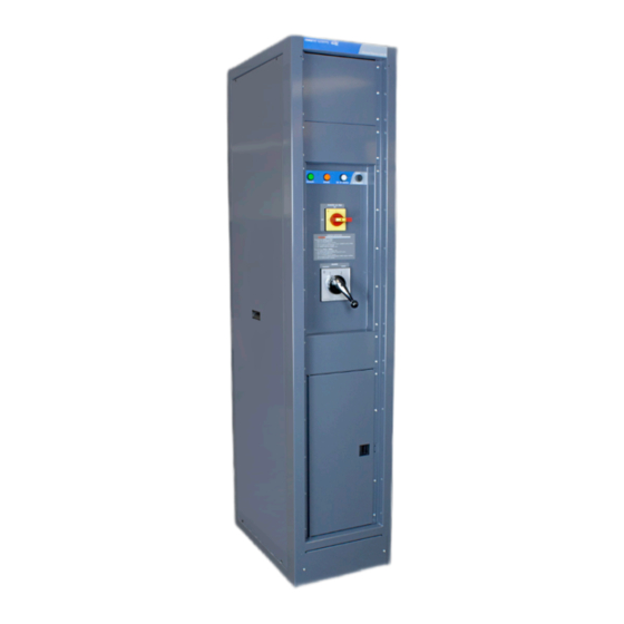
EXTERNAL WRAPAROUND
MANUAL BYPASS SWITCH (MBS)
Installation and Operation Manual V1.0
BEYOND THE INVERTER
THE NEW GENERATION OF POWER CONVERTERS
DUAL INPUT INVERTER
Commercial Power as default source
AC BACKUP IN A DC ENVIRONMENT
Leverage your existing DC infrastructure
ONE STOP SHOP
Wide output power range
HARSHEST AC INPUT CONDITIONS
Without compromising the quality of the AC output
Copyright © 2013. Construction electroniques & telecommunications S.A.
All rights reserved. The contents in document are subject to change without notice.
The products presented are protected by several international patents and trademarks.
Address: CE+T S.a, Rue du Charbonnage 12, B 4020 Wandre, Belgium
www.cet-power.com - info@cet-power.com
Important Safety Instructions
Save these Instructions
www.cet-power.com
Advertisement
Table of Contents

Subscribe to Our Youtube Channel
Related Manuals for CE+T Power 016-1895-10


Summary of Contents for CE+T Power 016-1895-10
- Page 1 EXTERNAL WRAPAROUND MANUAL BYPASS SWITCH (MBS) Installation and Operation Manual V1.0 BEYOND THE INVERTER THE NEW GENERATION OF POWER CONVERTERS DUAL INPUT INVERTER Commercial Power as default source AC BACKUP IN A DC ENVIRONMENT Leverage your existing DC infrastructure ONE STOP SHOP Wide output power range HARSHEST AC INPUT CONDITIONS Without compromising the quality of the AC output...
-
Page 2: Table Of Contents
Table of contents 1. CE+T at a glance ........................... 2. Abbreviations ............................3. Warranty and Safety Conditions ......................Disclaimer ........................... Technical care ..........................Installation ..........................3.3.1 Handling ......................... 3.3.2 Surge and transients ...................... 3.3.3 Other ..........................Maintenance ..........................Replacement and Dismantling ..................... 4. - Page 3 Switching from BYPASS to NORMAL .................... Emergency Interlock Release ....................... 9. Product Specifications ........................... Specifications ..........................10. Appendix ............................... 10.1 Mechanical Drawings ........................10.2 Supported Wire Sizes ........................– EMBS – Installation and Operation Manual – v1.0...
- Page 4 Release Note: Release date Modified page Version Modifications (DD/MM/YYYY) number 09/05/2018 First release of the Manual. – EMBS – Installation and Operation Manual – v1.0...
-
Page 5: Ce+T At A Glance
CE+T at a glance 1. CE+T at a glance CE+T Power designs, manufactures and markets a range of products for industrial operators with mission critical applications, who are not satisfied with existing AC backup systems performance and related maintenance costs. -
Page 6: Abbreviations
Abbreviations 2. Abbreviations Twin Sine Innovation Enhanced Power Conversion Regular Digital Signal Processor Alternating current Direct current Electro Static Discharge Main Earth Terminal Manual Bypass TCP/IP Transmission Control Protocol/Internet Protocol Universal Serial Bus Protective Earth (also called Ground / GND) Neutral Printed Circuit Board True Redundant Structure... -
Page 7: Warranty And Safety Conditions
Warranty and Safety Conditions 3. Warranty and Safety Conditions WARNING: The electronics in the power supply system are designed for an indoor, clean environment. When installed in a dusty and/or corrosive environment, indoor, it is important to: • Install an appropriate filter on the enclosure door, or on the room’s air conditioning system. •... -
Page 8: Installation
Warranty and Safety Conditions 3.3 Installation • This product is intended to be installed only in restricted access areas as defined by UL60950 and in accordance with the National Electric Code, ANSI/NFPA 70, or equivalent agencies. • The Inverter System may contain output over current protection in the form of circuit breakers. In addition to these circuit breakers, the user must observe the recommended UL listed upstream and downstream circuit breaker requirements as defined in this manual. -
Page 9: Surge And Transients
Warranty and Safety Conditions 3.3.2 Surge and transients The mains (AC) supply of the modular inverter system shall be fitted with Lightning surge suppression and Transient voltage surge suppression suitable for the application at hand. Manufacturer’s recommendations of installation shall be adhered to. -
Page 10: Purpose And Applicability
This document applies to the following models of the Comm/net Systems, Inc external wraparound wall-mounted manual bypass switch (MBS): • 016-1895-10 r02: MBS; Rack Cabinet; 250A; 120/208VAC; 3PH; Rotary Switch Type; Make-Before-Break; Handshake Interlock; Up to ( 4 ) 3-pole breaker positions. -
Page 11: Theory Of Operation
• Handshaking interlock feature compatible with CE+T inverters when bundled at time of purchase. • Rotary ON/OFF inverter AC feed switch to safely remove AC power from the inverter ( 016-1895-10 model ). Also allows testing of inverter while load is on Bypass. -
Page 12: Unpacking And Inspection
Unpacking and Inspection 6. Unpacking and Inspection The Comm/net Systems MBS was carefully packaged at the factory to withstand the normal rigors of shipping. However, you should carefully inspect the box and contents to confirm that no damage has occurred in transit. Most shipping carriers require notification of shipping damage within twenty-four hours of delivery, and it is the responsibility of the recipient to inspect the shipment immediately upon receipt. -
Page 13: Installation
Installation 7. Installation 7.1 Installation Preparation When selecting an installation location, ensure that all of the following conditions are met before proceeding. 7.1.1 Elevated Operating Ambient Temperature Take care to install the equipment in an environment compatible with the maximum ambient temperature ( TMA ) specified in Section 9, page 22. -
Page 14: Mounting
Installation 7.2 Mounting Notice: • This product must be installed within a restricted access location where access is through the use of a tool, lock and key or other means of security, and is controlled by the authority responsible for the location. This product must be installed and maintained only by qualified technicians. -
Page 15: Chassis Ground
Installation 7.3 Chassis Ground Caution: Do not energize the MBS before chassis ground is connected. The chassis ground is located on the top of the MBS cabinet (see Figure 6) . A two hole lug landing position is provided. See table below for termination information. -
Page 16: Alarm/Bypass Operation Signal Input Wiring
Installation 7.5 Alarm/Bypass Operation Signal Input Wiring Warning • Prior to cable termination, ensure inverter ac feed switch is in off/open (0) position, source switch is in inverter (1) position, and main Breaker, if equipped, is in off/open position. • Risk of electric shock. Can cause equipment damage, injury and death. •... -
Page 17: Power Cables
Installation 7.6 Power Cables Warning • Risk of electric shock. Can cause equipment damage, injury and death. • Multiple power sources are present, ensure all input power feeds are not energized before manipulating connections. Electrical installation should only be performed by qualified personnel with proper tools and protective safety equipment. -
Page 18: Adding Loads
Installation 7.7 Adding Loads Warning: Ensure Breakers are in the off position before proceeding. Step 1. Remove the deadfront panel by uninstalling the (9) #12-24 screws (see Figure 13) . Step 2. Terminate GROUND connection to GROUND bar (see Figure 14) . Figure 13. -
Page 19: Operation
8.1 Features Overview The MBS includes two rotary switches located on the front of the panel: • INVERTER AC FEED - this switch ( circuit breakers on 016-1895-10 model ) controls AC power to the inverter mains input. • SOURCE - this switch determines whether loads are fed from the inverter ( NORMAL ) output or from the mains ( BYPASS ). -
Page 20: Alarm Contacts
Operation 8.1.3 Alarm Contacts The MBS features alarm contacts that can be used to remotely monitor MBS status. The corresponding alarm relay will be active under any of the following conditions: • Mains AC Fail • SOURCE Switch Not in NORMAL Position •... -
Page 21: Emergency Interlock Release
Operation 8.4 Emergency Interlock Release Warning Be sure the two sources are synchronized prior to using this feature. Failure to do so may cause premature switch contact wear, switch damage, and/or loss of power to load equipment. In situations where the inverter cannot provide the ready signal ( inverter not yet installed, or inverter failure ), a means is provided to release the interlock at the MBS. -
Page 22: Product Specifications
Product Specifications 9. Product Specifications 9.1 Specifications Notice: Replace fuse with bussmann mdl type fuse and .05a/250v rating only. Caution: Indoor use only. TABLE 2. SPECIFICATIONS 016-1895-10 016-1898-10 Input Voltage 120/208 VAC 120/208 VAC Input Current 250 A 500 A... -
Page 23: Appendix
Appendix 10. Appendix 10.1 Mechanical Drawings Figure 22. 250A External Wraparound Manual Bypass Switch Dimensions (016-1895-10 Model) – EMBS – Installation and Operation Manual – v1.0... - Page 24 Appendix Figure 23. 500A External Wraparound Manual Bypass Switch Dimensions (016-1898-10 Model) – EMBS – Installation and Operation Manual – v1.0...
-
Page 25: Supported Wire Sizes
Appendix 10.2 Supported Wire Sizes TABLE 3. POWER TERMINAL BLOCKS (016-1895-10 MODEL) RECOMMENDED TORQUE WIRE GAUGE STUD THREAD VALUE 10 AWG - 350 kcmil 8 - 14 lb.ft (10-20 Nm) TABLE 4. POWER TERMINAL BLOCKS (016-1898-10 MODEL) RECOMMENDED TORQUE TERMINAL BLOCK...
Need help?
Do you have a question about the 016-1895-10 and is the answer not in the manual?
Questions and answers