
Subscribe to Our Youtube Channel
Related Manuals for FLENDER MDSS


Summary of Contents for FLENDER MDSS
- Page 1 Helical gear unit for drive systems for tubular mills Assembly and operating instructions A9111-01en Edition 06/2022 MDSS 1...3...
- Page 2 Original assembly and operating instructions A9111-01 Edition 06/2022 25/07/2022 Copyright (©2022 Flender GmbH) 16:26:30...
-
Page 3: Table Of Contents
Table of contents Introduction...............................11 Legal information ........................11 General information .........................12 Lubricants ..........................14 Safety instructions ...........................15 Security notes ..........................15 The five safety rules .........................15 General information .........................15 General warnings and symbols....................17 Special types of danger and personal protective equipment ........... 17 Intended use ..........................20 Description ..............................23 General description ........................23... - Page 4 Table of contents Transport..........................35 Attachment points ........................37 Special aspects of gear unit lubrication and preservation............39 4.4.1 Oil filling and oil drain .......................39 4.4.2 Preservation of gear units with Tacolab seals ................. 39 Assembly..............................41 General assembly instructions ....................41 Unpacking the gear unit ......................42 Gear unit assembly ........................43 5.3.1 Foundation ..........................43...
- Page 5 Table of contents Operation..............................67 Operating data .........................67 Irregularities in operation ......................67 Taking the unit out of service ....................68 Servicing ..............................69 General maintenance information....................69 Maintenance schedule ......................69 Maintenance and servicing work....................71 8.3.1 Cleaning the gear unit......................71 8.3.2 Cleaning the air filter and replacing the air filter element............71 8.3.2.1 Cleaning the air filter ........................71 8.3.2.2...
- Page 6 Table of contents Edition 06/2022 A9111-01en...
- Page 7 List of tables Table 2-1 Symbols and markings .......................16 Table 2-2 General warnings ........................17 Table 3-1 Designs and associated directions of rotation................23 Table 3-2 Information about the specific heat output .................28 Table 5-1 Information on screwing fastening bolts ..................59 Table 5-2 Preload forces and tightening torques ..................60 Table 7-1 Operating values ........................67 Table 8-1...
- Page 8 List of tables Edition 06/2022 A9111-01en...
- Page 9 Transport symbols........................37 Figure 4-2 Attachment points on a gear unit, model MDSS ................38 Figure 4-3 Oil filling and draining points on the MDSS type gear unit ............39 Figure 4-4 Preservation of gear units with Tacolab seals................40 Figure 5-1 Gap dimension at grease labyrinth ....................44 Figure 5-2...
- Page 10 List of figures Edition 06/2022 A9111-01en...
-
Page 11: Introduction
Introduction Naming convention This product, which can be used as a gear reduction unit or multiplier gear unit, is referred to below as "gear unit". Legal information 1.1 Legal information Warning system These instructions contain information you must observe for your own personal safety as well as to avoid damage to property and persons. -
Page 12: General Information
Please note the following: WARNING Flender products are only suitable for the uses set out in the catalogue and associated technical documentation. If third-party products and components are used, these must be recommended and/or authorised by Flender. Safe and flawless operation of the products requires proper transport, proper storage, setup, assembly, installation, commissioning, operation and maintenance. - Page 13 Copyright The copyright of these instructions is held by Flender. Without the authorisation of Flender, these instructions may not be used wholly or in parts for competitors’ purposes or be given to third parties. If you have any technical queries, please contact the Customer Services address (Page 79).
-
Page 14: Lubricants
Flender recommends regular inspection to ascertain whether the selected lubricating oil is still approved by Flender. If it is not, another brand of oil should be selected instead. Edition 06/2022... -
Page 15: Safety Instructions
In order to safeguard plants, systems, machines and networks against cyber threats it is ne- cessary to implement (and continually maintain) a holistic industrial security concept that cor- responds to the current state of the art. Flender products and solutions undergo continuous development in this respect. - Page 16 Safety instructions 2.3 General information Symbols on the gear unit The following symbols apply to the gear unit; some of which are found as coloured markings on the gear unit: Points labelled on the gear unit Symbol Coloured markings Earth connection point Air relief point yellow Oil filling point...
-
Page 17: General Warnings And Symbols
Safety instructions 2.4 General warnings and symbols Points labelled on the gear unit Symbol Coloured markings These symbols indicate that the oil dip- stick must be firmly screwed in. Table 2-1: Symbols and markings General warnings and symbols 2.4 General warnings and symbols The following table contains general warnings and their associated symbols. - Page 18 Safety instructions 2.5 Special types of danger and personal protective equipment DANGER Electric shock Live parts can cause electric shock. Ensure that the entire plant is de-energised before starting electrical installation work. Protective equipment Wear the following personal protective equipment when handling the gear unit: •...
- Page 19 Safety instructions 2.5 Special types of danger and personal protective equipment Surface temperature The surface temperatures of the gear unit can become very extreme depending on the oper- ating conditions. WARNING Risk of burns Possible risk of serious burn injury from hot surfaces (> 55 °C). Wear suitable protective gloves and protective clothing.
-
Page 20: Intended Use
Flender will accept no liability or warranty whatsoever for damage occurring as a result of the use of non-approved replacement parts. The same applies to any accessories which were not supplied by Flender. - Page 21 Safety instructions 2.6 Intended use • Cleaning the outside of the gear unit with a high-pressure cleaning device is not permit- ted. • Do not perform any welding work anywhere on the gear unit or connected parts. Do not use the gear unit or connected parts as an earthing point for electric-welding operations. Gear parts and rolling-contact bearings may be irreparably damaged by welding.
- Page 22 Safety instructions 2.6 Intended use Edition 06/2022 A9111-01en...
-
Page 23: Description
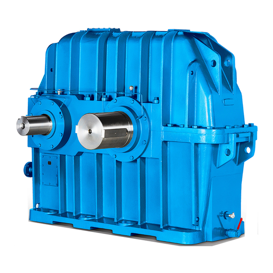
General description 3.1 General description ® The FLENDER helical gear unit (referred to below simply as “gear unit”) described in these instructions has been developed to drive conveyor systems. The gear unit is available as a single-stage helical gear unit. The gear unit is designed for a horizontal mounting position. -
Page 24: Figure 3-1 Plate: Lubrication Point
The grease lubrication points are designated using the following plate: Figure 3-1: Plate: Lubrication point Gear unit components The diagram below shows the available gear unit components for a model MDSS gear unit: Figure 3-2: Gear unit components on a model MDSS gear unit ①... -
Page 25: Oil Supply To The Gear Unit
Description 3.3 Oil supply to the gear unit More information Additional information and a detailed illustration of the gear unit can be found in the dimen- sion drawing provided in the complete gear unit documentation. Oil supply to the gear unit 3.3 Oil supply to the gear unit Introduction The individual gear unit parts and components are supplied with oil from an oil supply sys-... -
Page 26: Tacolab Seal
Description 3.5 Shaft seal 3.5.1 Tacolab seal 3.5 Shaft seal Features Tacolab seals are non-contact, low-maintenance seals that do not wear. It is not therefore necessary to interrupt operation in order to service or replace them. The Tacolab seal is a combination of two sealing elements: •... -
Page 27: Cooling
Description 3.6 Cooling NOTICE Gear unit leaks caused by poor sealing Gear unit leaks caused by poor sealing are possible. Regrease the labyrinth seals at the specified regreasing intervals. The regreasing intervals are specified in the Maintenance schedule (Page 69). Further information Check in the spare parts drawing and the spare parts list as to whether the gear unit is equipped with Tacolab seals. -
Page 28: Heating
Description 3.8 Heating More information You can find additional information about the couplings in the coupling instructions provided in the complete gear unit documentation. Heating 3.8 Heating Introduction At low temperatures, it may be necessary to preheat the gear unit oil before the drive is switched on or also during operation. -
Page 29: Oil Level Indicator
Description 3.9 Oil level indicator Information Install the heating elements in the oil supply system tank. More information You can find additional information about the position of the mounted components and a de- tailed illustration of the gear unit in the dimension drawing in the complete documentation for the gear unit. -
Page 30: Bearing Monitoring
Description 3.11 Bearing monitoring The following diagram shows an oil-temperature monitoring system mounted on the gear unit: Figure 3-4: Oil-temperature monitoring system for gear units, model MDSS ① Pt 100 resistance thermometer More information More information, a detailed illustration of the gear unit and the position of the mounted com- ponents can be found in the dimension drawing in the complete documentation for the gear unit. -
Page 31: Bearing Monitoring By Shock-Pulse Transducer
Description 3.11 Bearing monitoring The following diagram shows bearing monitoring using a Pt 100 resistance thermometer: Figure 3-5: Bearing monitoring using a Pt 100 resistance thermometer ① Pt 100 resistance thermometer More information More information, a detailed illustration of the gear unit and the position of the mounted com- ponents can be found in the dimension drawing in the complete documentation for the gear unit. -
Page 32: Figure 3-6 Fully Assembled Accelerometer (A), And Threaded Connection (B) For Variants 1 To 4
Description 3.11 Bearing monitoring The following diagram shows the fully assembled accelerometer (A), and the threaded con- nection (B) for variants 1 to 4: Figure 3-6: Fully assembled accelerometer (A), and threaded connection (B) for variants 1 to 4 ① Shielded cable (oil-proof) ④... - Page 33 Description 3.11 Bearing monitoring More information You can find more information and a detailed illustration of the gear unit with attached sensors in the dimension drawing, which is part of the complete documentation of the gear unit. More information about the sensors can be found in the instructions for the sensors. A9111-01en Edition 06/2022...
- Page 34 Description 3.11 Bearing monitoring Edition 06/2022 A9111-01en...
-
Page 35: Application Planning
Application planning Scope of delivery 4.1 Scope of delivery The scope of delivery is listed in the shipping documents. Immediately upon receiving the gearbox, check that everything has been delivered. Report any damaged and/or missing parts to Customer Services (Page 79) immediately. WARNING Serious injury through defective product Serious injury may occur. - Page 36 Application planning 4.2 Transport NOTICE Damage to gear unit When transporting the gear unit, the gear unit packaging or coating can be damaged. When transporting the product in a lifted position, proceed slowly and carefully in order to avoid damage to the packaging or coating. NOTICE Damage to gear unit due to impacts against free shaft ends Damage to gear unit is possible due to impacts against the free shaft ends.
-
Page 37: Attachment Points
Application planning 4.3 Attachment points The symbols which appear on the packaging must be observed. Figure 4-1: Transport symbols Attachment points 4.3 Attachment points Lifting eyes Lifting eyes are fitted to the gear unit to assist with its transportation during manufacture and installation. -
Page 38: Figure 4-2 Attachment Points On A Gear Unit, Model Mdss
The diagram below shows the position of the attachment points for a gear unit, model MDSS: Figure 4-2: Attachment points on a gear unit, model MDSS Drive units with additional components mounted on the gear unit (such as drive motor, coup- ling, etc.) may require an extra attachment point owing to the displacement in the centre of gravity caused by the mounted components. -
Page 39: Special Aspects Of Gear Unit Lubrication And Preservation
Oil filling and oil drain 4.4 Special aspects of gear unit lubrication and preservation The diagram below shows the oil filling points and the oil draining points on type MDSS gear units: Figure 4-3: Oil filling and draining points on the MDSS type gear unit ①... -
Page 40: Figure 4-4 Preservation Of Gear Units With Tacolab Seals
Application planning 4.4 Special aspects of gear unit lubrication and preservation The diagram below shows the procedure for preserving gear units with Tacolab seals: Figure 4-4: Preservation of gear units with Tacolab seals ① Adhesive tape ③ Labyrinth, filled with grease, can be re- greased ②... -
Page 41: Assembly
Assembly General assembly instructions 5.1 General assembly instructions Assembly work must be performed very carefully by authorised, trained and suitably instruc- ted personnel. Liability is excluded for damage caused by the incorrect performance of this work. Requirements Improper use can damage the gear unit. Take the following precautions: •... -
Page 42: Unpacking The Gear Unit
Assembly 5.2 Unpacking the gear unit WARNING Ignition of vapours emitted from solvents There is a risk of injury due to ignition of vapours emitted from solvents during cleaning work. Please note the following: • Ensure sufficient ventilation. • Do not smoke. Unpacking the gear unit 5.2 Unpacking the gear unit Introduction... -
Page 43: Gear Unit Assembly
Assembly 5.3 Gear unit assembly Procedure To unpack and use the gear unit, please proceed as follows: 1. Remove packaging and transport devices in accordance with regulations. 2. Visually inspect for damage and dirt. 3. Report any damaged or missing parts to Customer Service (Page 79) immediately. 4. -
Page 44: Description Of Assembly Work
Assembly 5.3 Gear unit assembly Further information Further information about dimensions, space requirements and arrangement of supply con- nections can be found in the complete documentation for the gear unit. 5.3.2 Description of assembly work 5.3 Gear unit assembly CAUTION Risk of chemical burns from chemical substances There is a risk of chemical burns when handling aggressive cleaning agents. -
Page 45: Alignment
Assembly 5.3 Gear unit assembly NOTICE Sparking, inadmissible temperature rise and shaft seal wear due to insufficient gap dimension An insufficient gap dimension can cause sparking, inadmissible temperature rise and shaft seal wear. If the shaft is sealed by Taconite or Tacolab seals, make sure that the set gap dimension +0.5 of 1 mm at the grease labyrinth is not altered when the input and output elements (e.g. -
Page 46: Mounting The Gear Unit On The Housing Mounting Foot
Assembly 5.3 Gear unit assembly The following diagram shows the alignment surfaces and alignment screws for gear units, model MDSS: Figure 5-3: Alignment surfaces and alignment screws for gear units, model MDSS ① Alignment surface ② Alignment screw More information Further information and the precise position of the alignment thread are provided in the di- mension drawing in the overall gear unit documentation. - Page 47 Assembly 5.3 Gear unit assembly It is not permissible to transport the gear unit using the lifting eyes on the upper section of the gear unit housing. The lifting eyes on the upper section of the gear unit housing are only used to lift the upper housing section.
-
Page 48: Mounting On A Concrete Foundation Using Stone Bolts Or Foundation Blocks
Assembly 5.3 Gear unit assembly 5.3.3.2 Mounting on a concrete foundation using stone bolts or foundation blocks 5.3 Gear unit assembly Requirement The lower side of the gear unit feet must be clean. Mounting a gear unit using stone bolts The following diagram shows a stone bolt: Figure 5-4: Stone bolt ①... -
Page 49: Figure 5-5 Foundation Block
Assembly 5.3 Gear unit assembly Mounting gear units using foundation blocks The following diagram shows a foundation block: Figure 5-5: Foundation block ① Fastening bolt ⑥ Foundation ② Washer ⑦ Foundation block ③ Gear unit foot ⑧ Flat steel plate ④ Height of the completed foundation ⑨... -
Page 50: Mounting On A Concrete Foundation Using Anchor Bolts
Assembly 5.3 Gear unit assembly 5.3.3.3 Mounting on a concrete foundation using anchor bolts 5.3 Gear unit assembly Requirement The lower side of the gear unit feet must be clean. Inserting the anchor bolt The following diagram shows the inserted anchor bolt: Figure 5-6: Inserted anchor bolt ①... -
Page 51: Figure 5-7 Tightened Anchor Bolt
Assembly 5.3 Gear unit assembly Mounting the gear unit using anchor bolts The following diagram shows a tightened anchor bolt: Figure 5-7: Tightened anchor bolt ① Hexagon nut ⑤ Raw foundation ② Washer ⑥ Anchor bolt ③ Housing foot ⑦ Baseplate ④ Fine-grout concrete ⑧... -
Page 52: Couplings
Assembly 5.4 Couplings CAUTION Incorrect use of the pre-tensioning device Incorrectly using the pre-tensioning device can result in injury. To ensure correct handling and adjustment of the pre-tensioning device, you must carefully comply with the instructions provided by the manufacturer of the pre-tensioning device. NOTICE Lack of strength in concrete Damage caused by inadequate stability of the gear unit as a result of inadequate concrete... -
Page 53: Assembling The Coupling
Assembly 5.4 Couplings More information You can find additional information about the coupling in the coupling instructions provided in the complete gear unit documentation. 5.4.1 Assembling the coupling 5.4 Couplings Introduction The method used to mount the coupling varies according to model. The procedure described in these instructions is general rather than specific to one type of coupling. -
Page 54: Aligning The Coupling
• Make sure that the maximum permissible misalignment values are not exceeded during operation. – If you are using couplings supplied by Flender, you will find the maximum permissible misalignment values in the instructions for the coupling. – If you are using couplings supplied by other manufacturers, contact them and ask them for the maximum permissible misalignment values, making sure that you specify the potential radial loads for your application. -
Page 55: Figure 5-8 Possible Misalignments
Assembly 5.4 Couplings The diagram below illustrates the potential misalignments: Figure 5-8: Possible misalignments Alignment Align the individual components in two mutually perpendicular axial planes. The following can be used as alignment tools: • Ruler (radial misalignment) • Feeler gauge (angular misalignment) •... -
Page 56: Connecting Components
Assembly 5.5 Connecting components More information You can find more information on the permissible alignment errors in the instructions for the coupling, which are part of the complete documentation of the gear unit, or contact the man- ufacturer in question. Connecting components 5.5 Connecting components 5.5.1... -
Page 57: Heating Element Connection
Assembly 5.5 Connecting components More information You can find additional information on pressure monitoring in the pressure monitor instruc- tions provided in the complete gear unit documentation. 5.5.4 Heating element connection 5.5 Connecting components Procedure To connect heating elements to the gear unit, proceed as follows: 1. -
Page 58: Electrical Connections
Assembly 5.5 Connecting components More information You can find additional information on the Pt 100 resistance thermometer in the Pt 100 res- istance thermometer instructions, which are part of the complete documentation of the gear unit. 5.5.7 Electrical connections 5.5 Connecting components Procedure DANGER Electric shock... -
Page 59: Bolt Connection Classes
Assembly 5.6 Tightening procedure Information Replacing bolts Replace any bolts that are no longer fit for use by bolts of the same type and strength class. Mating threads The mating threads must have the following properties: • Made of steel or cast iron •... -
Page 60: Tightening Torques And Preload Forces
Assembly 5.6 Tightening procedure 5.6.3 Tightening torques and preload forces 5.6 Tightening procedure The specified bolt connections must be tightened to the torques stated in the table below. The tightening torques apply to friction values of μ = 0.14. total The following table lists the preload forces and tightening torques for bolt connections, strength classes 8.8;... -
Page 61: Final Work
Assembly 5.7 Final work Nominal Strength Preload force for bolt connection Tightening torque for bolt connec- thread dia- class of classes from table in the Chapter tion classes from table in the meter the bolt “Bolt connection classes” Chapter “Bolt connection (Page 59) classes”... - Page 62 Assembly 5.7 Final work • Check the alignment after tightening the fastening elements. The alignment must not have changed in any way. • Lock the oil drainage valves against accidental opening. • Protect the gear unit against falling objects. • Check that the guards over rotating parts are securely fastened. Contact (accidental or deliberate) with rotating parts is not permitted.
-
Page 63: Commissioning
Carefully ensure that the pre-lubrication phase is not longer than 5 minutes as the oil can foam up at low temperatures. For oil temperatures below 10 °C, heat up the oil using suit- able measures and contact Flender in this regard. Further information You can find additional information on the oil cooling system in the separate data sheet, and in the equipment list in the complete gear unit documentation. -
Page 64: Running The Gear Unit For The First Time
Commissioning 6.2 Measures during commissioning • For gear units with oil supply system: Check that the oil supply system is working prop- erly. • Check the oil level. • Measure the oil sump temperature (Page 72) after the gear unit has run in. •... - Page 65 Commissioning 6.2 Measures during commissioning • Ensure that the heating elements are not exposed. • Check the switching points of the temperature monitor. WARNING The oil sump can catch fire The oil sump can catch fire if exposed heating elements are switched on. Never switch on the heating elements until you have checked that they are completely im- mersed in the oil bath.
- Page 66 Commissioning 6.2 Measures during commissioning Edition 06/2022 A9111-01en...
-
Page 67: Operation
Operation Operating data 7.1 Operating data Introduction To ensure correct, trouble-free operation of the system, observe the operating values of the gear unit. The operating value specified in the Appendix “Technical data” apply. The following operating values apply to the oil: Maximum operating temperat- 80 °C applicable for mineral oil, API groups I or II, and saturated synthetic ester... -
Page 68: Taking The Unit Out Of Service
1. Switch off the drive aggregate if it exhibits irregular behaviour during operation 2. Refer to the “Fault information” (Page 74) to find the cause of the fault. 3. If you still cannot determine the cause of the fault, contact Flender Customer Service (Page 79). -
Page 69: Servicing
Servicing General maintenance information 8.1 General maintenance information The operator must ensure compliance with the stipulated time limits. This also applies if the maintenance activities are included in the operator’s internal maintenance schedules. The gear unit could be damaged if the stipulated intervals for maintenance and servicing work are not observed. -
Page 70: Table 8-1 Maintenance And Servicing Activities
Servicing 8.2 Maintenance schedule Intervals and time limits Measures Monthly and prior to every start-up Check for leaks Check the oil level 400 operating hours after commissioning Check the water content of the oil Change the oil (or depending on results of the oil sample test) Check that the fastening bolts are tight Every 3 months... -
Page 71: Maintenance And Servicing Work
Servicing 8.3 Maintenance and servicing work More information about installed components can be found in the instructions for the com- ponents in the complete documentation for the gear unit. Maintenance and servicing work 8.3 Maintenance and servicing work Introduction You can find maintenance and servicing measures relating to gear unit lubrication and pre- servation, which are not provided in this chapter, in instructions 7300 in the complete docu- mentation for the gear unit. -
Page 72: Replacing The Air Filter Element
4. Compare the measured value with the maximum permissible oil temperature (Page 67). 5. Immediately stop the gear unit if the maximum permissible oil temperature is exceeded. Contact Flender Customer Service (Page 79). 8.3.4 Measuring the vibration levels of the rolling-contact bearings 8.3 Maintenance and servicing work... -
Page 73: Measuring The Temperature At The Rolling-Contact Bearings
8.3 Maintenance and servicing work General inspection of the gear unit by Customer Services Arrange for Flender Customer Services to perform a general inspection on the gear unit. Thanks to their experience, these engineers are best placed to assess which gear unit com- ponents need to be replaced. -
Page 74: Final Work
8.4 Possible faults The faults listed below are only intended as a troubleshooting guide. If any faults occur while the unit is still under warranty, do not allow anyone except Flender Customer Service to attempt a repair. Even after the warranty period has expired, you should still arrange for faults to be rectified by Flender Customer Service. - Page 75 Servicing 8.4 Possible faults Possible faults Causes Possible remedies Outer surface of gear Inadequate sealing of the housing • Seal housing cover or joints unit soiled with oil cover or joints Labyrinth seals soiled with oil, in- • Check oil filling correct transport position •...
- Page 76 Servicing 8.4 Possible faults Possible faults Causes Possible remedies Oil is foaming in the Oil supply system left in operation • Switch off the oil supply system gear unit for too long at low temperatures • Degas the oil Gear unit too cold in operation •...
- Page 77 Servicing 8.4 Possible faults Possible faults Causes Possible remedies Elevated temperature For gear units with fan: Air intake • Clean the air guide cover and gear unit housing during operation opening in air guide cover or gear unit housing is soiled Coolant temperature too high •...
-
Page 78: Table 8-2 Possible Faults And How To Rectify Them
Servicing 8.4 Possible faults Possible faults Causes Possible remedies Water in the oil Oil foams in the oil sump • Take test tube sample to examine oil condition for water penetration • Have the oil examined by a chemical lab Table 8-2: Possible faults and how to rectify them Edition 06/2022 A9111-01en... -
Page 79: Service & Support
Customer Service addresses: Flender GmbH Am Industriepark 2 46562 Voerde Germany Tel.: +49 (0)2871 / 92‐0 Fax: +49 (0)2871 / 92‐1544 More information Further information about service and support can be found on the Internet: Service & Support (https://www.flender.com/service) A9111-01en Edition 06/2022... - Page 80 Service & Support 9.1 Contact Edition 06/2022 A9111-01en...
-
Page 81: Disposal
Disposal Disposal of the gear unit When disposing of the gear unit after its useful life, please observe the following measures: • Remove operating oil, preservative agents and coolant from the gear unit and dispose of it according to regulations. •... - Page 82 Disposal Edition 06/2022 A9111-01en...
-
Page 83: Spare Parts
Flender will accept no liability or warranty whatsoever for damage occurring as a result of the use of non-approved replacement parts. The same applies to any accessories which were not supplied by Flender. - Page 84 Spare parts Edition 06/2022 A9111-01en...
-
Page 85: Declaration Of Incorporation
Declaration of incorporation Declaration of Incorporation Declaration of Incorporation Business name and full address of manufacturer: Flender GmbH Am Industriepark 2 46562 Voerde Germany Name and address of the person authorised to compile the relevant technical documentation: Mark Zundel Flender GmbH... - Page 86 Declaration of incorporation Declaration of Incorporation Edition 06/2022 A9111-01en...
-
Page 87: Technical Data
⑭ Hotline The limits of the intended use of the gear unit are defined on the basis of these data and the contractual agreements concerning the gear unit concluded between Flender and the cus- tomer. More information Further information about these technical data can be found in the separate data sheet and the dimension drawings in the complete documentation for the gear unit. -
Page 88: Ambient Temperature
By applying various suit- able measures, the gear unit can be used in the ambient temperature range extending from -40 °C up to 60 °C. However, this must always be authorised by Flender and specified in the order text. - Page 89 Technical data Enveloping surface sound pressure level Data on the enveloping surface sound pressure level are only possible for these gear units in specific cases. A9111-01en Edition 06/2022...
- Page 90 Technical data Enveloping surface sound pressure level Edition 06/2022 A9111-01en...
-
Page 91: Index
Index Fault rectification, 74 Fault-finding, 74 Final work, 61 Air filter, 71 Air filter element, 72 Alignment Alignment surface, 45 Prealignment, 45 Gear unit components, 24 Attachment points, 41 Gear unit designs, 23 Gear unit housing, 23 Gear unit markings, 16 Gear unit use, 20 General inspection of the gear unit, 73 Bearing monitoring Grease lubrication point, 24 Accelerometer, 31 Resistance thermometer, 30... - Page 92 Index Oil, 14 Warning symbols, 17 Oil level indicator, 29 Oil supply, 25 Oil supply system, 25, 27 Commissioning, 63 Oil temperature Checking, 72 Oil-temperature monitoring system Connecting the resistance thermometer, 57 Resistance thermometer, 29 Structure, 30 Operating values, 67 Oil, 67 Ordering replacement parts, 83 Pressure monitor, 27 Pressure monitoring, 27 Protective equipment, 18 Rating plate, 87 Example of model and size, 88 Rolling-contact bearings Measure temperature, 73...
- Page 94 Helical gear unit for drive systems for tubular mills Assembly and operating instructions A9111-01en Edition 06/2022 Flender GmbH Alfred-Flender-Straße 77 46395 Bocholt Germany...
Need help?
Do you have a question about the MDSS and is the answer not in the manual?
Questions and answers